07 assignment CNC
This week we were asked to design something that can be made on a CNC. CNC means Computer Numerical Code. This is a machine that
can run a milling operation with great precision. A CNC runs on a code also known as G code, this is a very well known code that still
get used today in a lot of machines in industries. It is also a very simple and easy code that can be learned in a short time. I learned
g code at Ho technical University in Ghana. It took me only two weeks to get a good insight on how to make simple parts. For example if I
wanted to make a small square I would write:
Today there are CAD programs and CNC programers who do this job for you. With that being
said, I used Autodesk inventor to design my project this week. Reason being that I find it easier to make multiple for assembly. The overall
way that you use Inventor to assembly parts and check for interference is much smoother. It also allows the use of Fusion 360 for the manufacturing
process.
As the files form inventor are comparable with fusion we can either convert them with in autodesk or just open the ipt file with fusion and it will
convert the files by itself when opening.
Multiple Computer Storage Station
I work at the University in Kleve Germany and teach middle and high school kids STEM which is organized bei ZDI Kleve. Do thing has been a great opportunity
in many rewarding ways. But a major problem has been poping up along the way. I some times have to transport 16 laptops to other classes rooms across the
University campus. Let me tell you if you think that laptops are light and weigh next to nothing, boy are you wrong. I been conversing with my professor
who is a great inspiration and has been teaching me how to teach and become a better student. After a couple of conversations we thought of buy a
computer storage station. This now has turned into a project for this week. Rather than spending well over 300 Euros, why not design and build our own
storage station?
There are sixteen laptops, so we need minium of 16 storage shelves, a way of charging them, and the storage station should also server as a pedestal that can be
used to teach of off, letting us place our laptop on top. After looking at these requirements making a couple of sketches on paper and finding the right dimensions,
I decided to use Inventor to design the parts for the reasons I mentioned above.
Design phase
Lets have a look at the design, as the labs are closed on weekends. Looking at requirements the decision was made to have the computer station (CS), have a height of 1200mm, 420mm deep, and a width of
650mm. The first thing to do in CAD was the base and the top which has the connections for the joints. There are somethings to take under consideration here. Normal wood
working joints won't work here. Even though this hurt my inner wood worker who really hate joints that have holes here we needed to account for the square conners of the joining pieces.
To do this we want to add 4 drill holes. In this case 6mm drill bit. To make the joints in one go and avoid having it to use the CNC as drill, you can use one tool. By having added the
fillets we are allowing the tool later to cut everything in one go saving time by avoiding another tool change. This also means you needed to use a smaller milling bit, here I will use a
5mm bit. Does the same job as the 6mm.
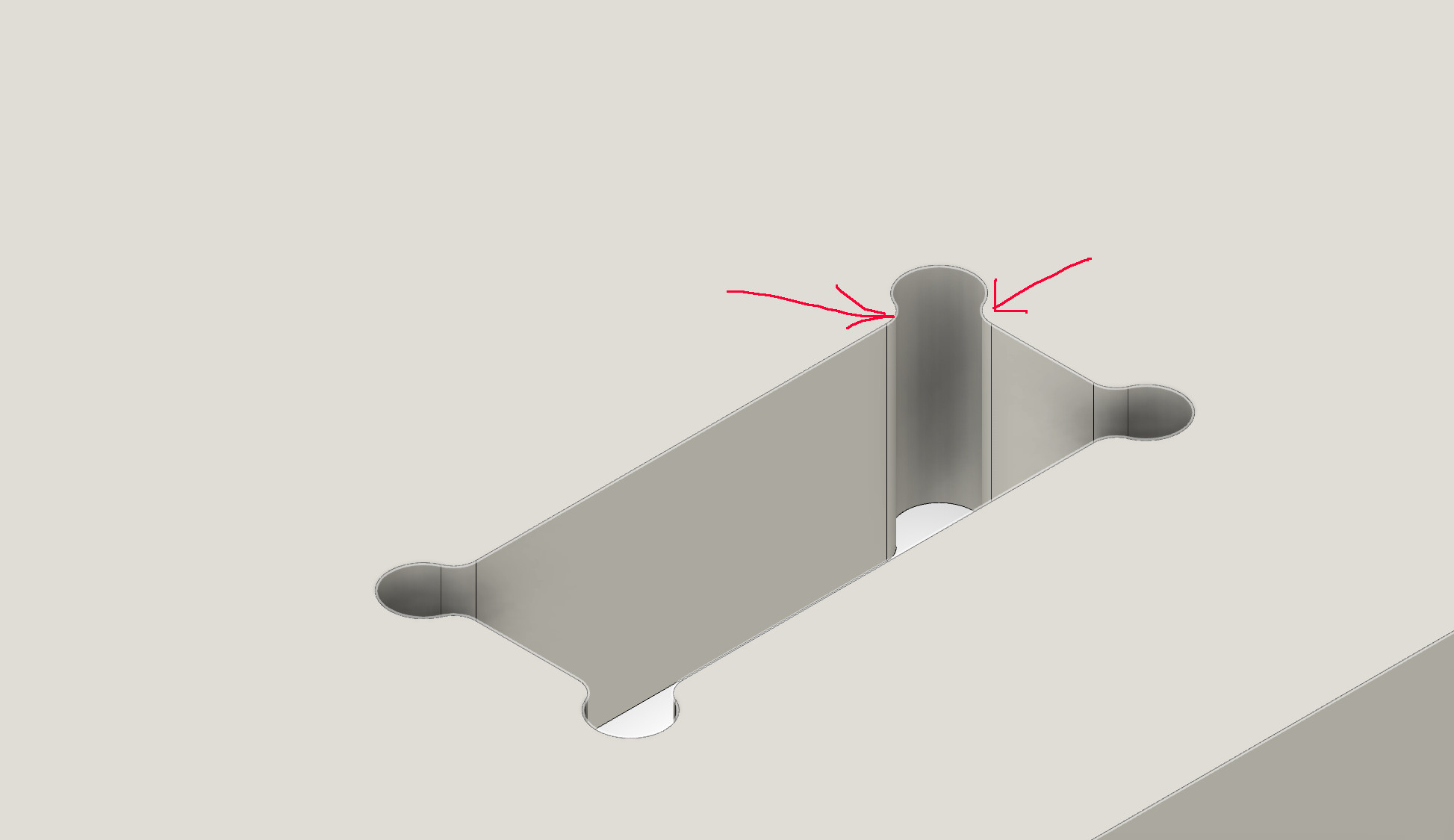
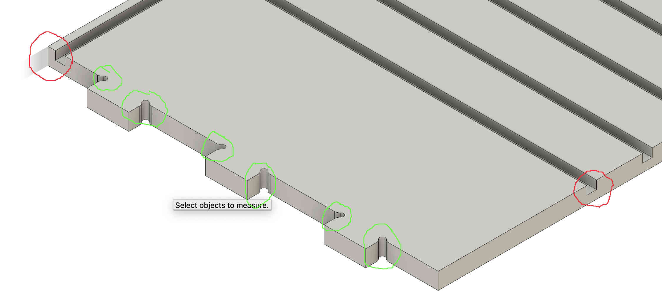
The rest of the design was just as simple. The joints will not requirement a glue up as they are a interference fit and will be held to gather thanks the to the physics of friction. On the sides I added mortises where I could add shelves and adjust them as needed. These I choice to make 10mm wide and 9mm deep. In red the mortieses and the in green you can see the fillets better with a radius of 6mm.
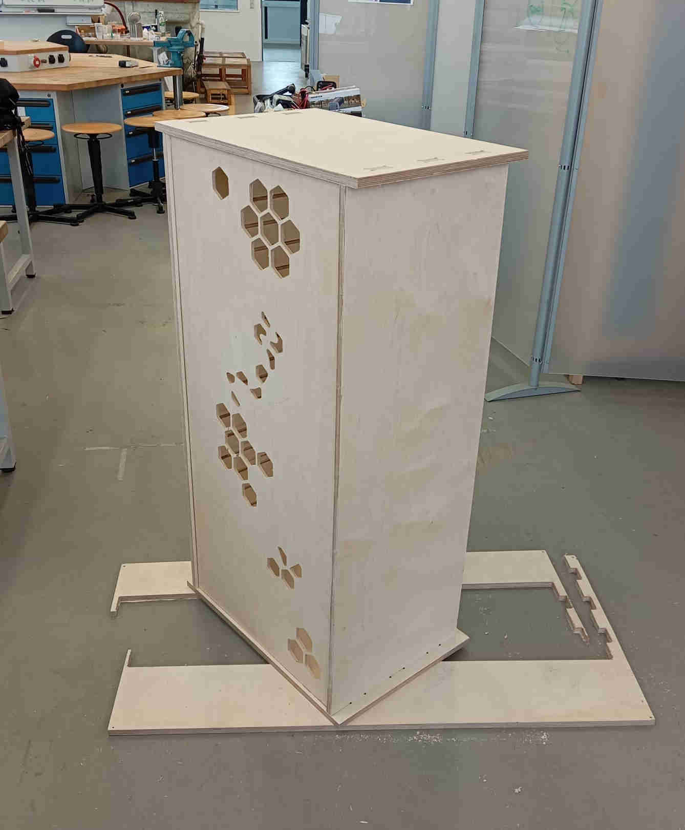
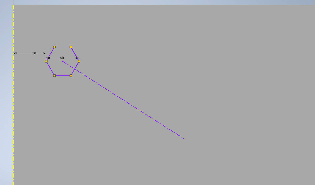
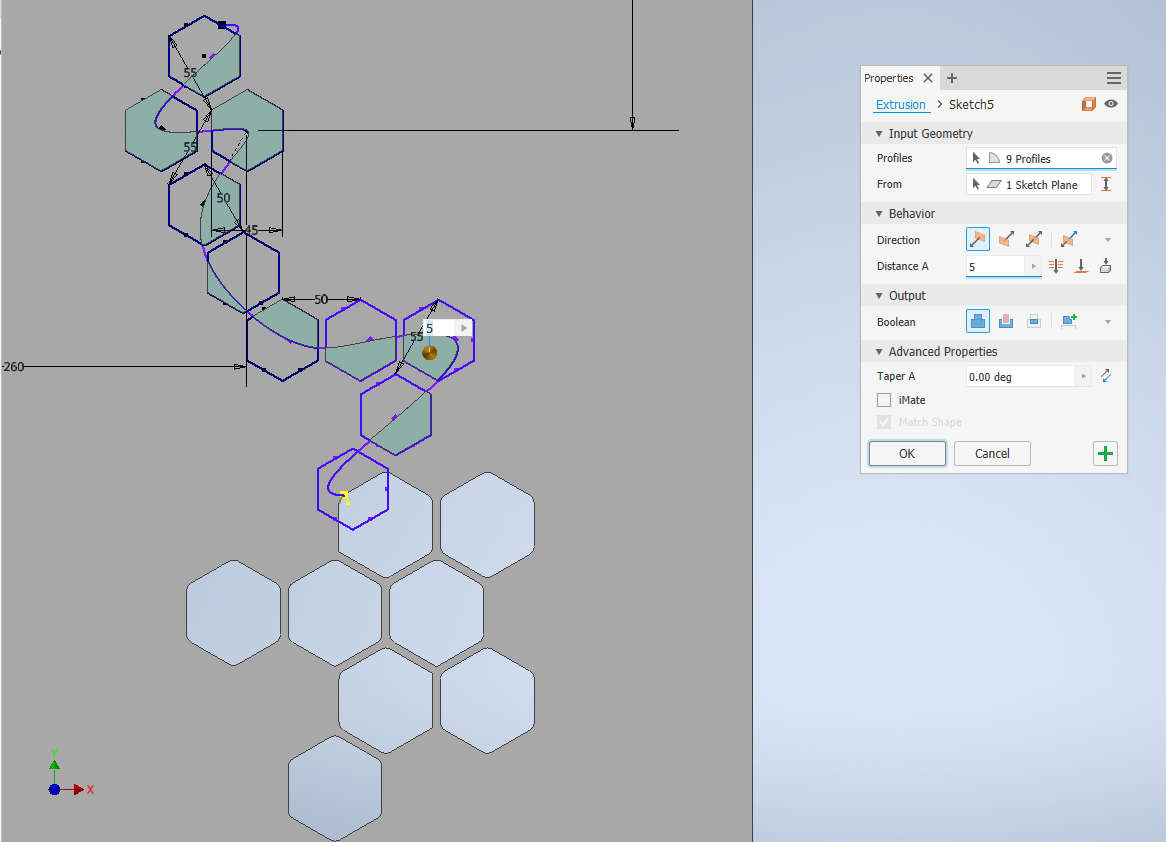
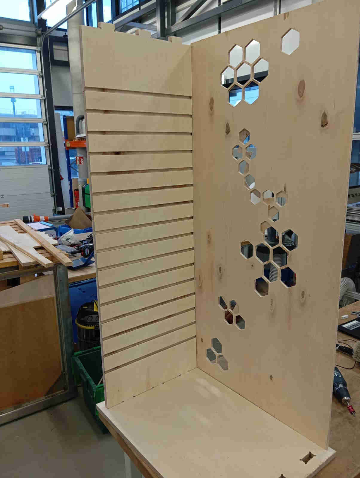
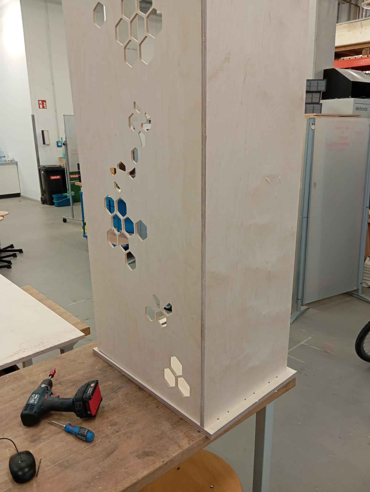
On the back wall which is 10mm thick plywood I decieded to add some vent holes so that when the laptops are charging air can flow through the CS. Here I went with hexagones and got a little creative.
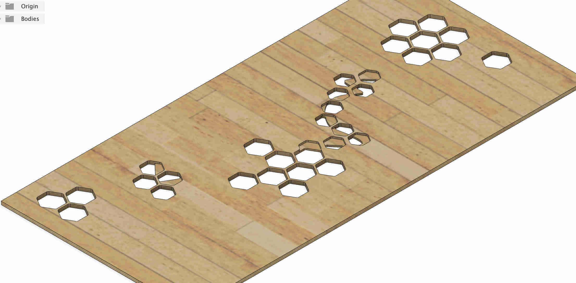
Screen shots of assembly
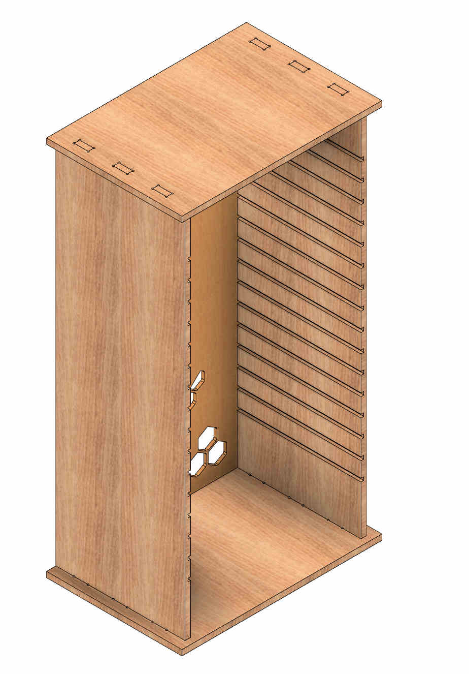
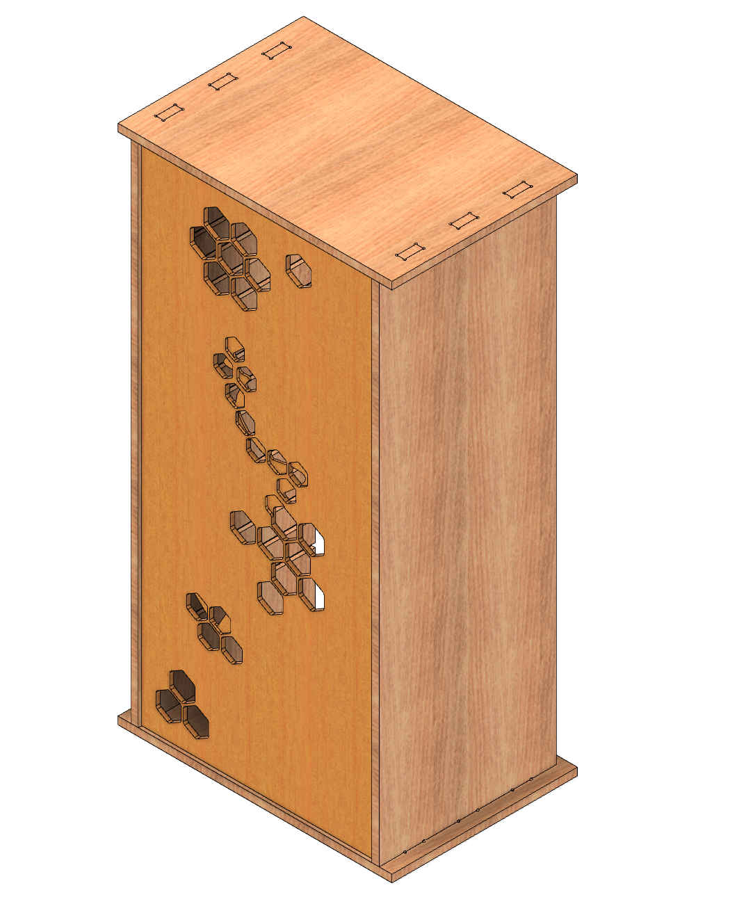
If you would like to make this storage station as well, click here to download the files
How to set up fusion for the CNC process
As I have used Autodesk Inventor, there is the need to convert the files. There are two was of doing this. The simplest and fastest was is to just open the files with
fusion 360. Which is the way I would recommended as the other work around is slow and requires to run two CAD software programmes on your pc. Your CPU wont like this
to much, as well as the GPU.
Open fusion, goto File > Open > Open from this computer > select your file and click open. This will take a little as Fusion will need to convert the files and you will
need to save them to fusion. Once this is done go to drop down menu design click the drop down arrow and goto manufacturing.
Next you want to go to the top right menu and select Manage > select Machine library.
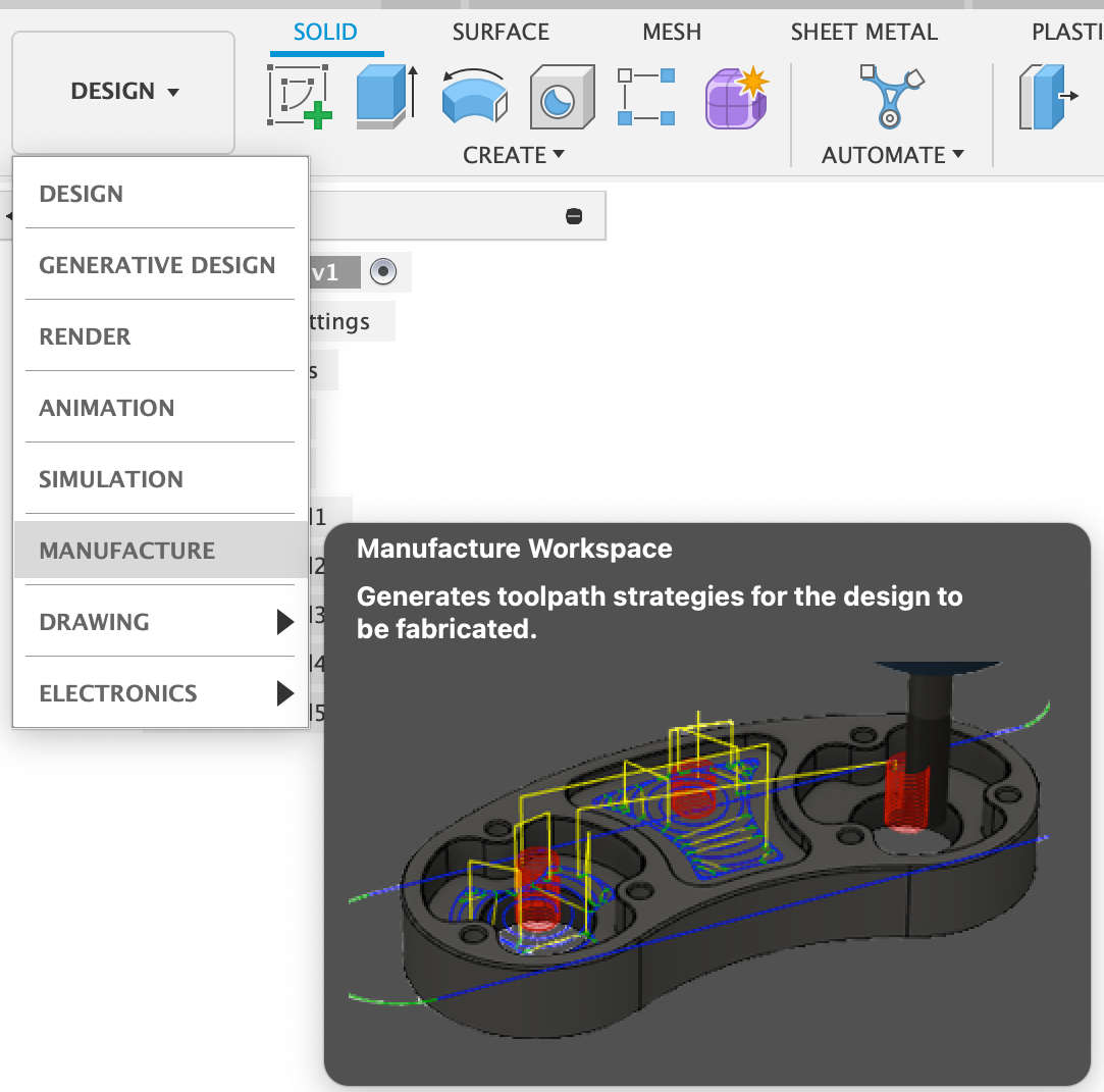
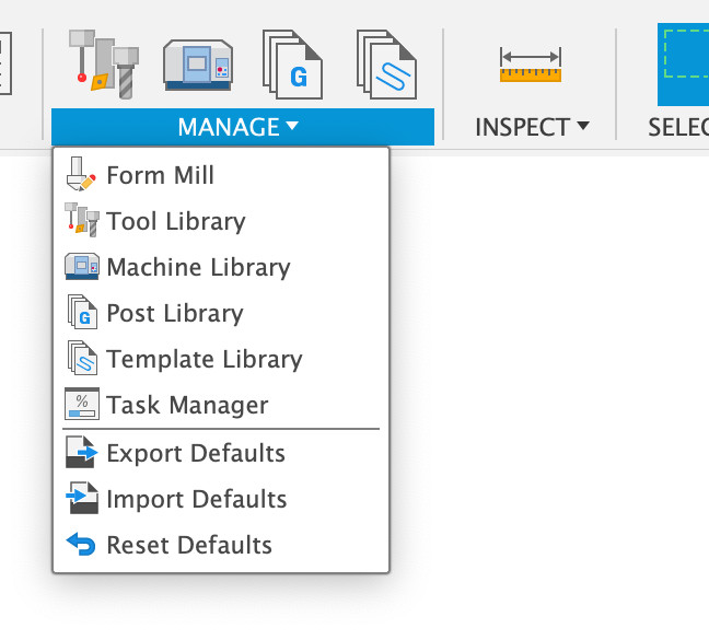
Here you can add just about any machine you want to use. Even creating your own parameters for the machine. As I do not want to get in to this subject much there is great video that explains the process better, even how to add off brands or ones that you have created yourself. Fusion does have a very large library of machines to pick from. For example: 3D printing, CNC, Lathe, and many other machines.
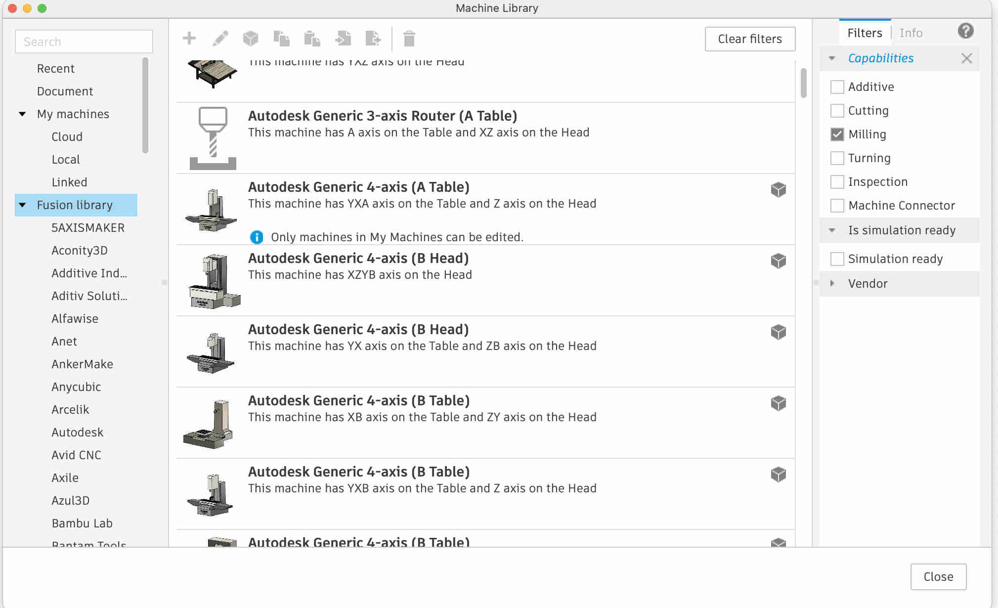
The CNC process
once you have the CNC machine picked out and all the parameters of the CNC having been added. we can finally get started on the process of creating the tool paths that the cnc can follow. The first thing that you want do is make sure that your Orign point is set up correctly. to this right click on setup > select New Setup.
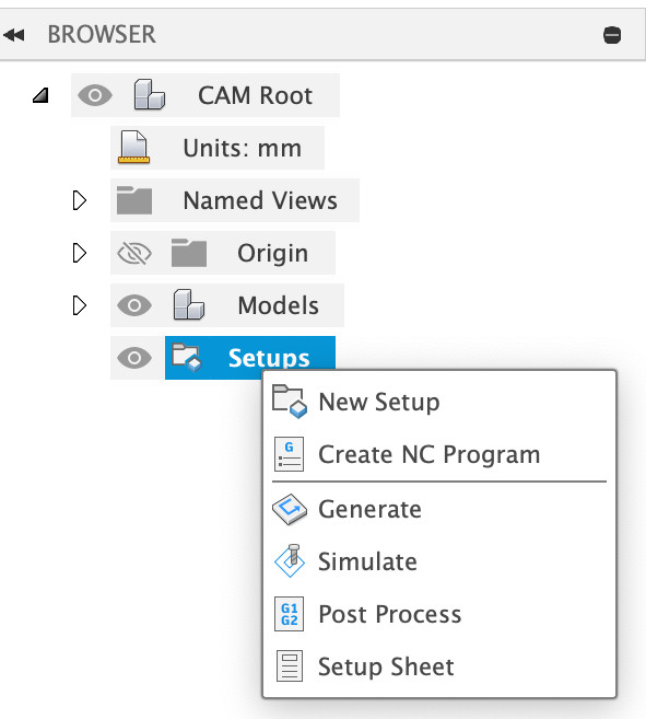
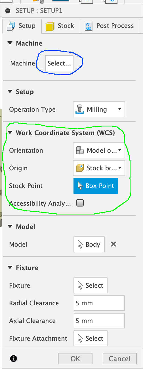
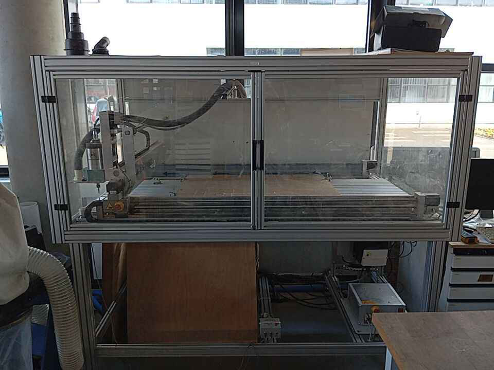
At this point pick the CNC that you want to with, here highlighted in Blue. For me this was the hobby grade High-Z S-1400/T-105 CNC Fräse. This next part here highlighted in green is very important. This helps us help the CNC find the work pieces origen. If this is set up improperly the CNC can not do it job correctly. Therefore make sure to do this process slowly and double check. One of the most embarrassing things that has happened top me with the CNC is that I had the cordinate System setup so that everything was happening outside of the CNC. So to avoid this mistake make sure that the main set is done correctly. Here is a before and after screen shot.
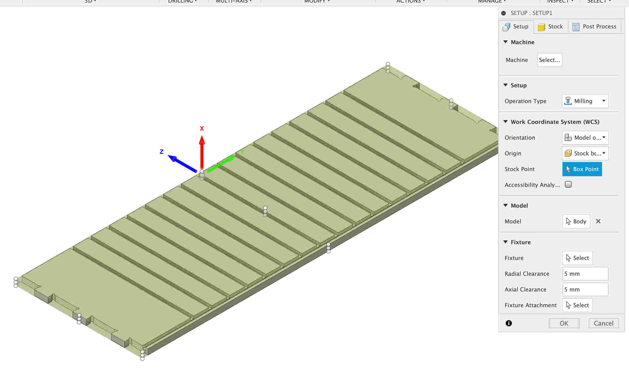
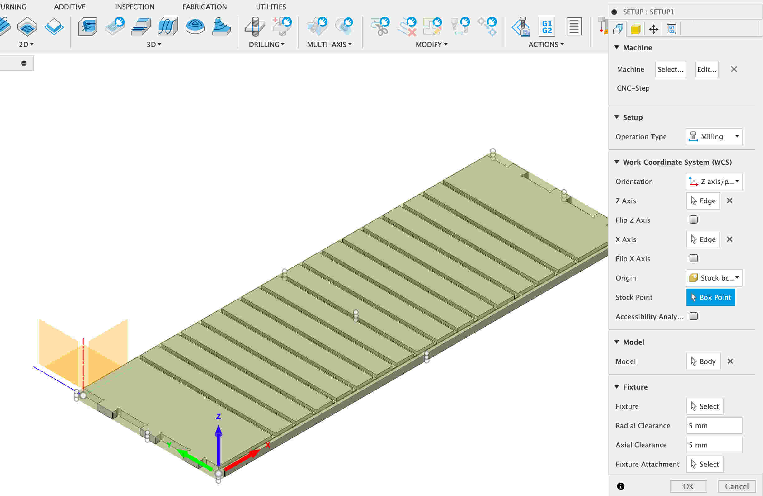
You will need to know where the CNC's XY axis are setup. Lets setup the axis. To do this look at the WCS (Work Coordinate System). in Orientation and select Z axis/plan and X axis. Next simply select the an edge that you want the Z coordinate to be on. If it is pointing down, select flip Z. Do the same with the X axis. once every axis is facing the right direction click okay.
Setup tools and cut paths
Next we need to find out what path and what tools we will use to do the CNC routing. The we need to know what we are going to rout. In this case here we have two contours. The inner ones, which I would suggest to cut first. Reason that we do not want the work piece to move later when routing out our contours. Go to the top of the menu and pickout 2D contour. In the pop up menu we want to select the tool that we need, click select.
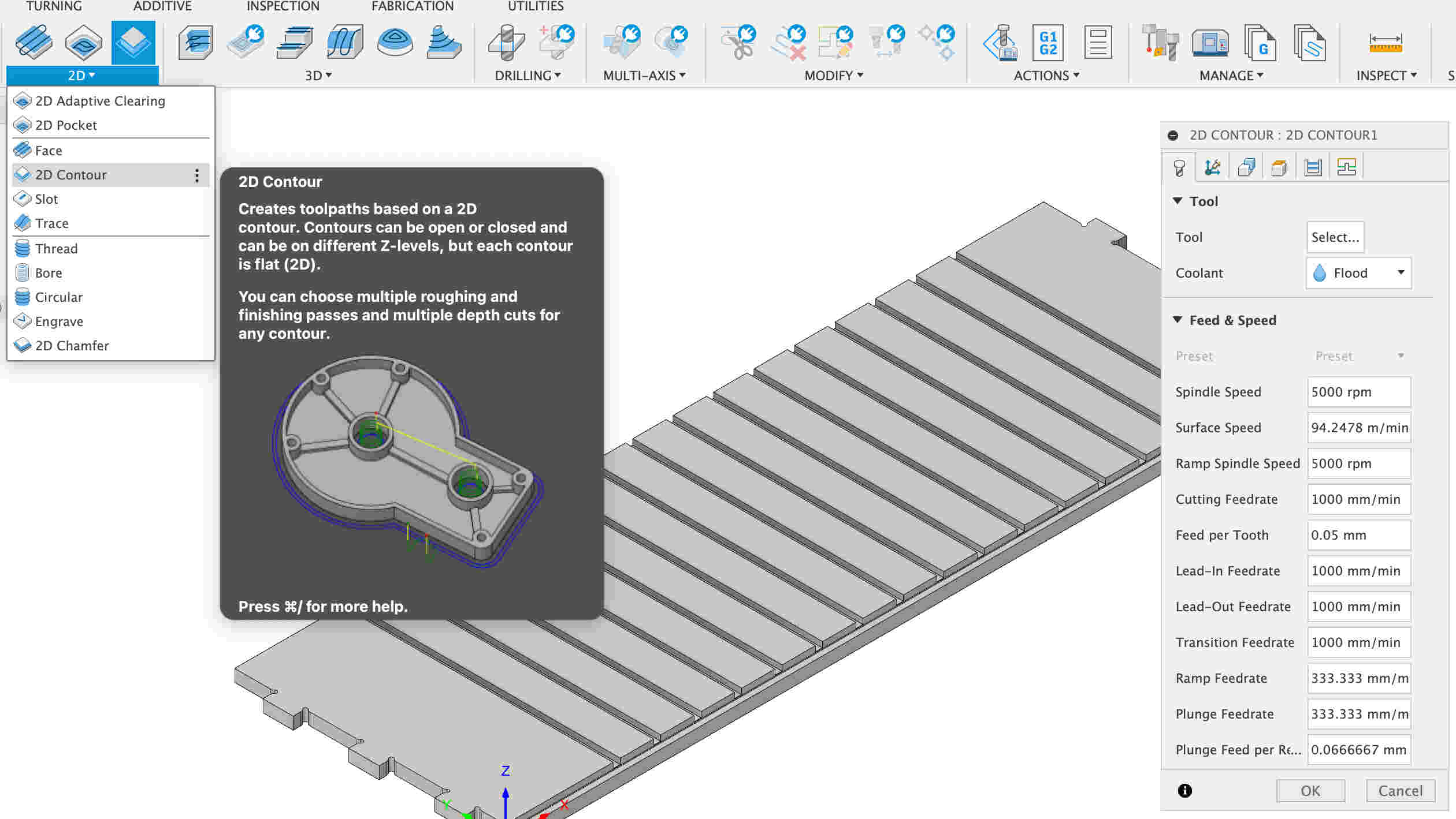
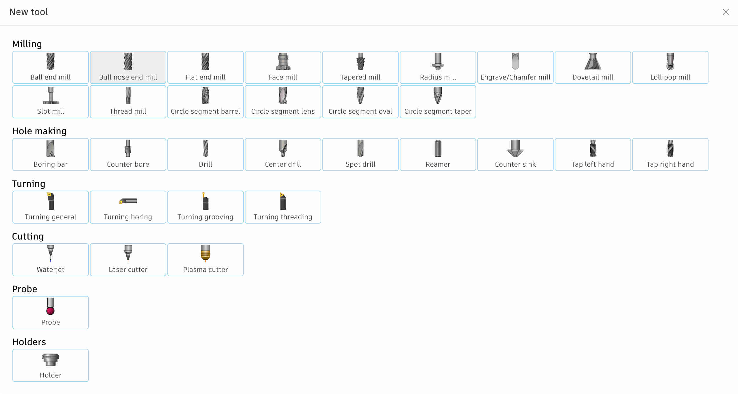
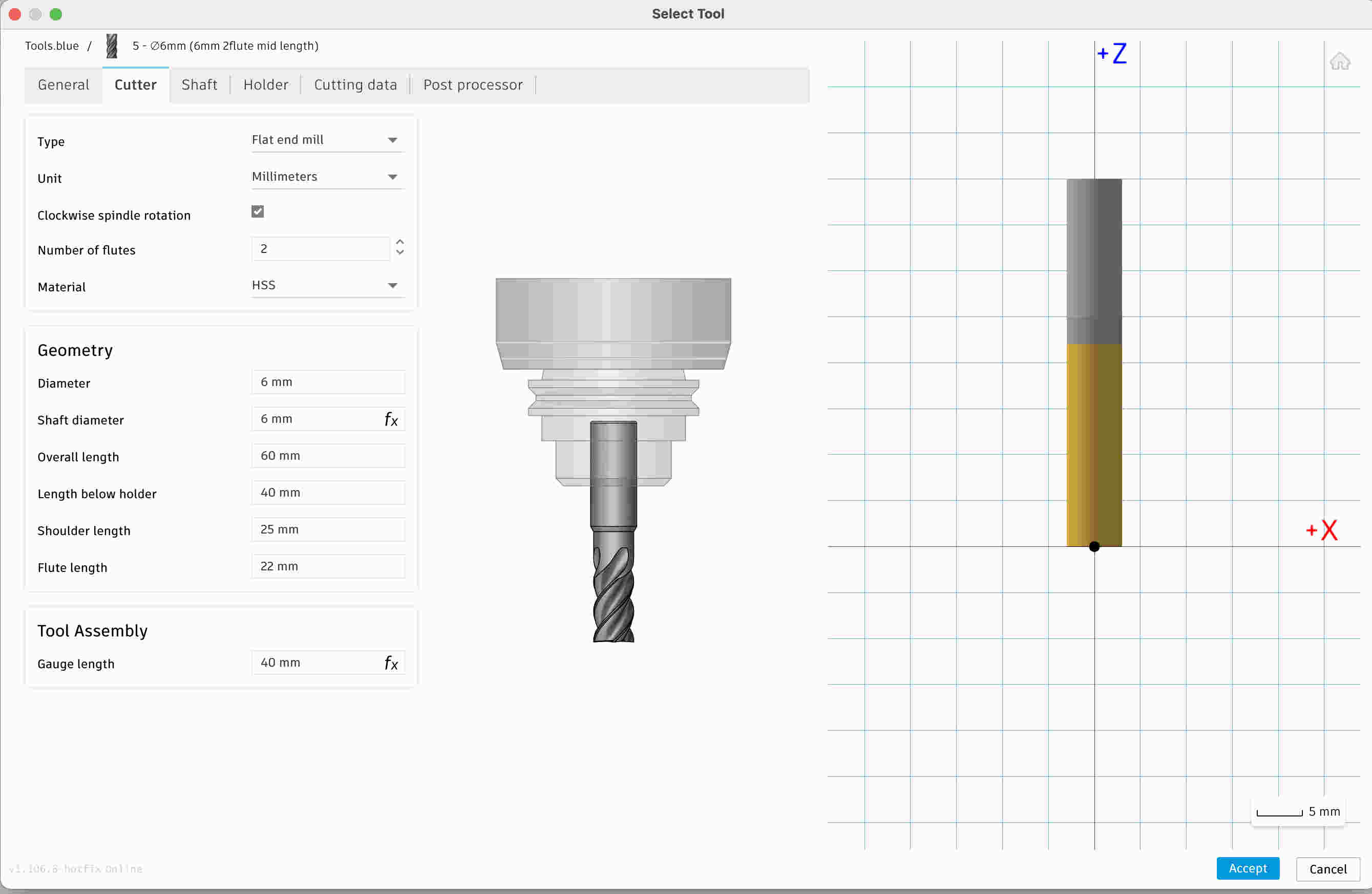
Selecting a tool is simple we can add tools to the library and save them there. If the tool is no in the current library select the plus symbol. the second menu that will pop up is tool type menu. Here select flat end mill, you will need some caliper to measure tools dimensions in oder to add them to your tool library.
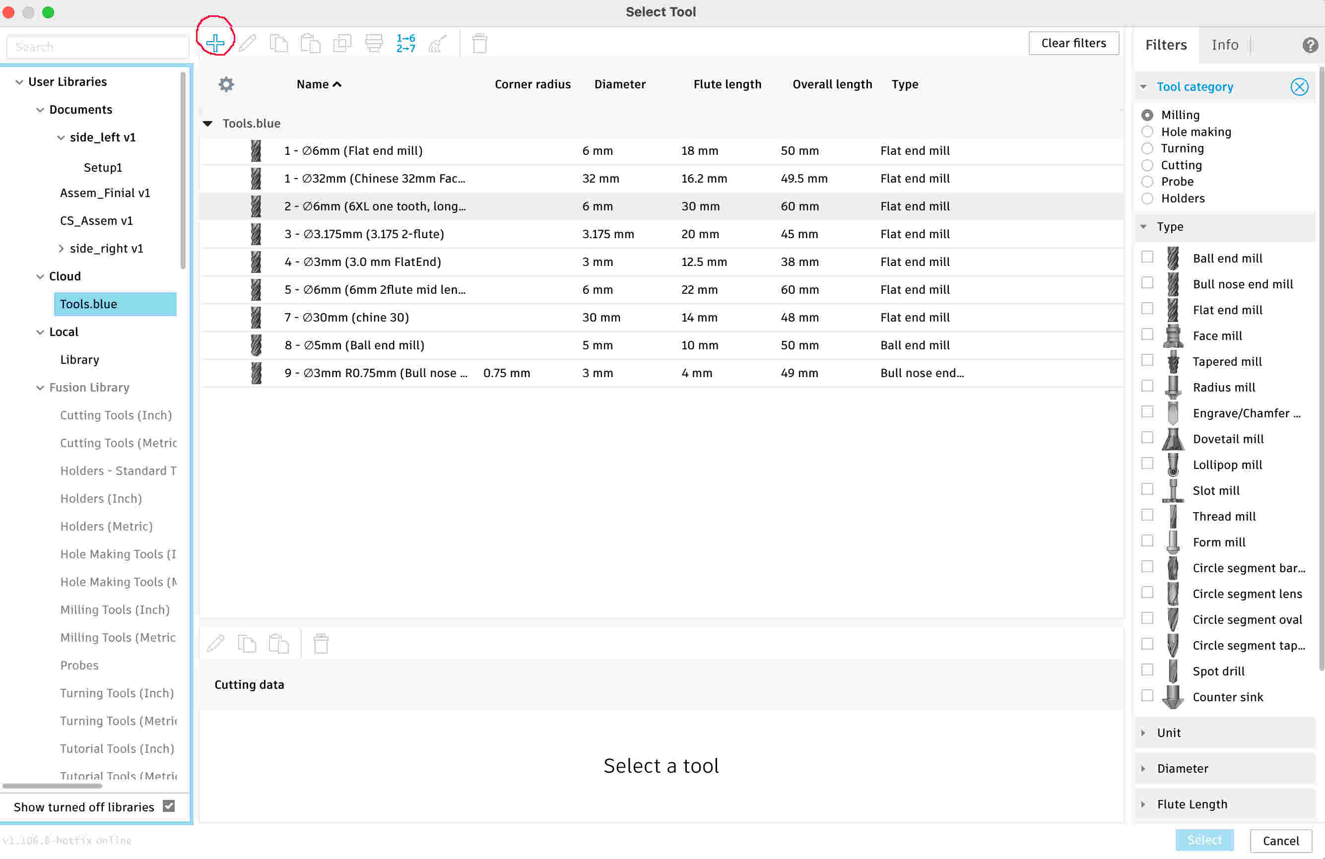
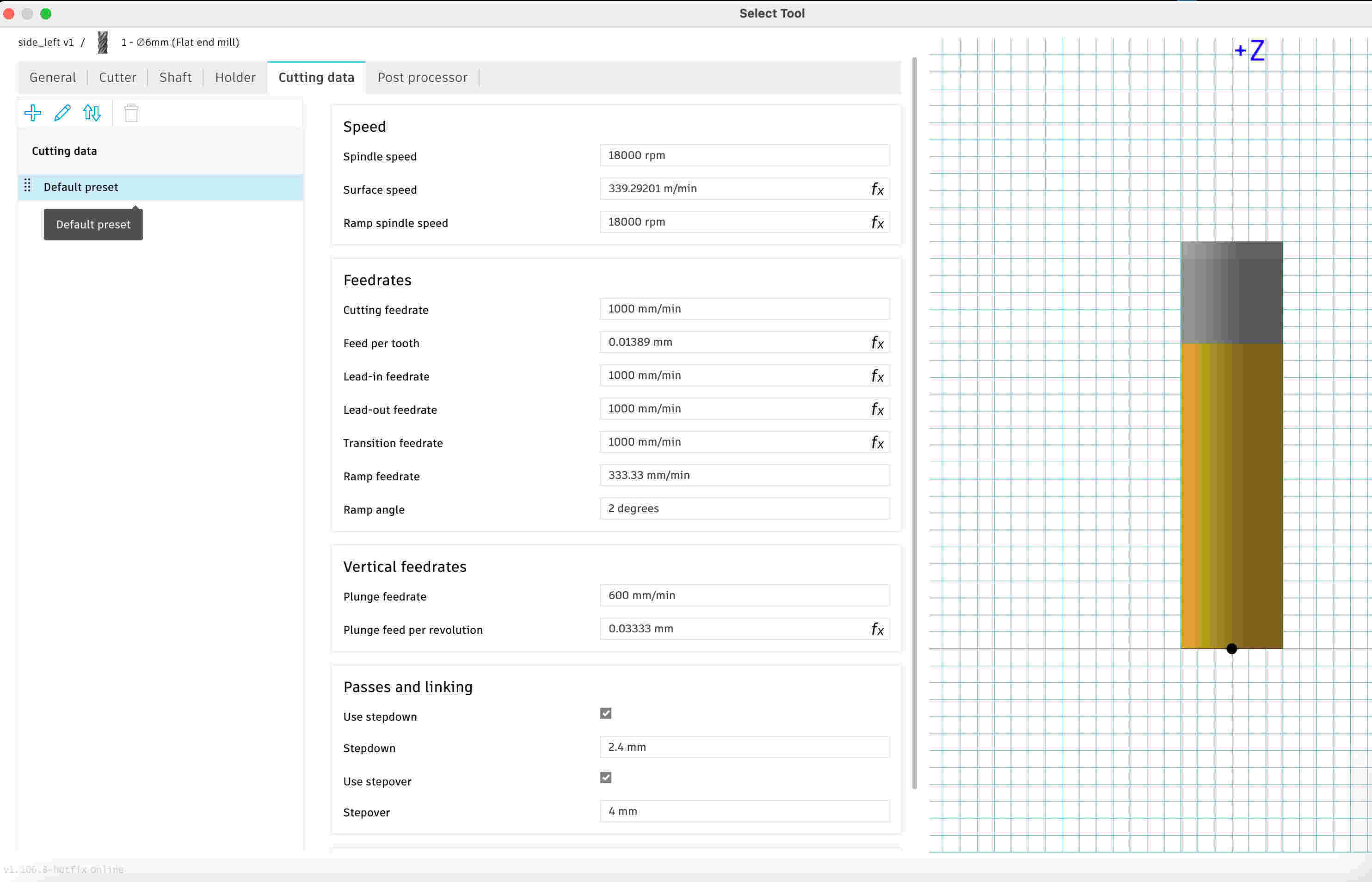
Here is an example on a flat end mill that is very common . In the cutting data tab you can add tools spindle speeds and feed rates. If your CNC does not have coolant you can disable this feature the tool a the bottom of the menu. Which can not been in this screen shot.
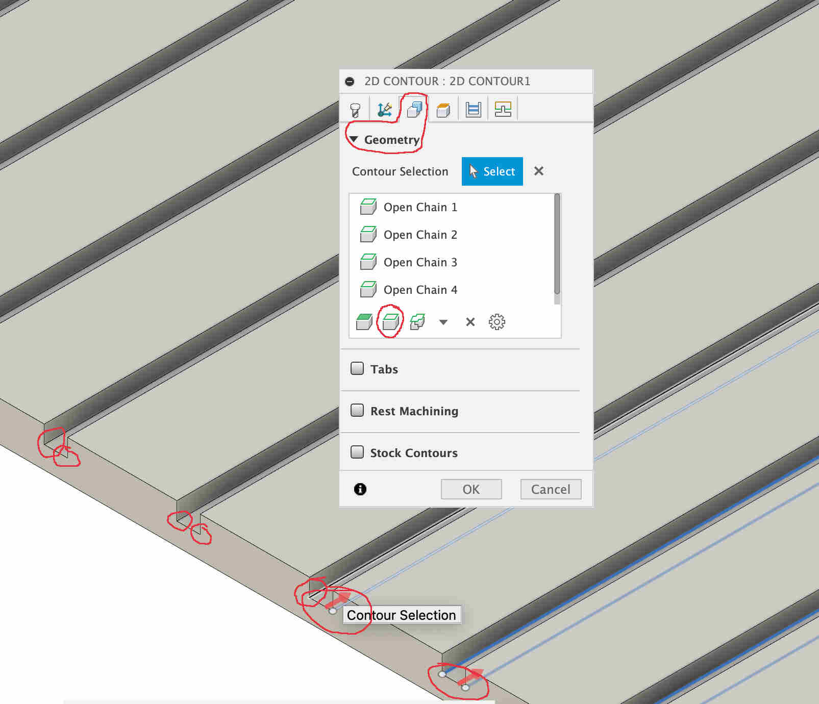
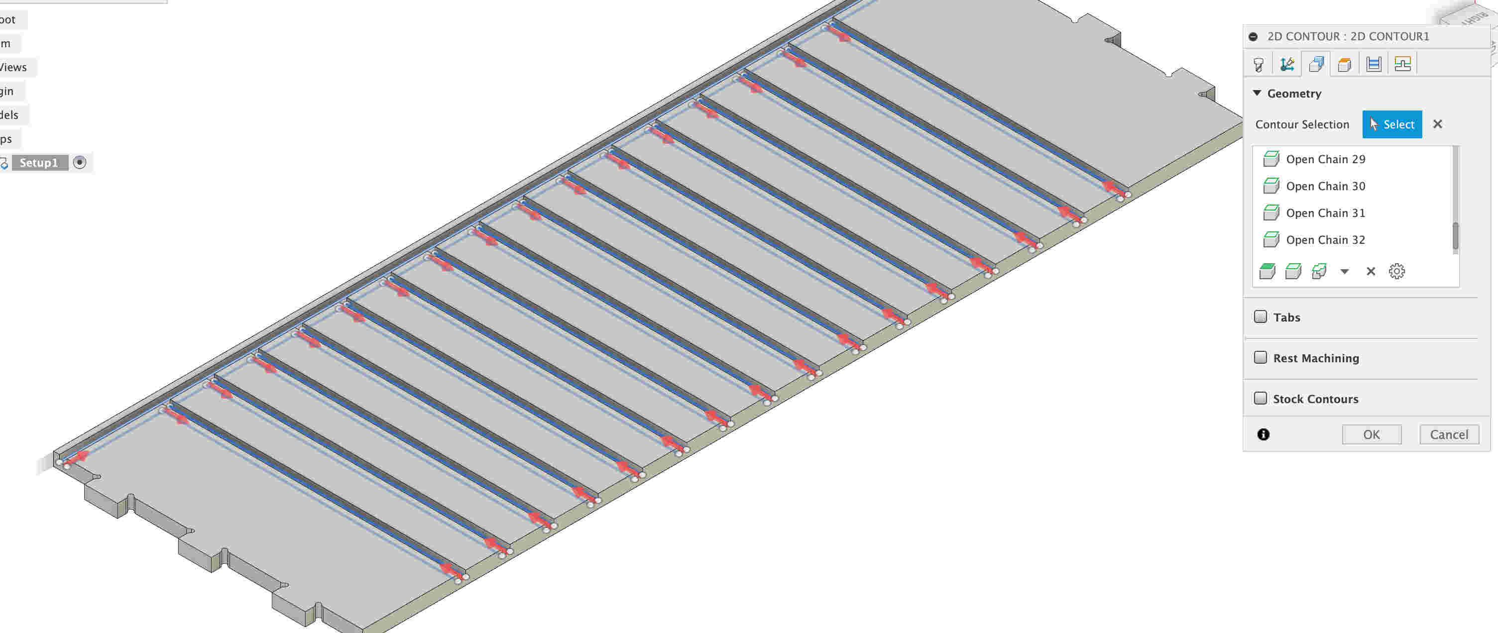
Now that tool has been added and selected we can continue with selecting our tool paths in the Geometry tab. Here I suggest picking the contours that are at the bottom. You can however pick out the face surface but I find that it is not as good. This is my personal experience with working with CNCs. In the image below highlighted in red are the contours that have been picked out, once picked out the contour lines should be blue with red arrows. To the right you see how everything looks when selected.
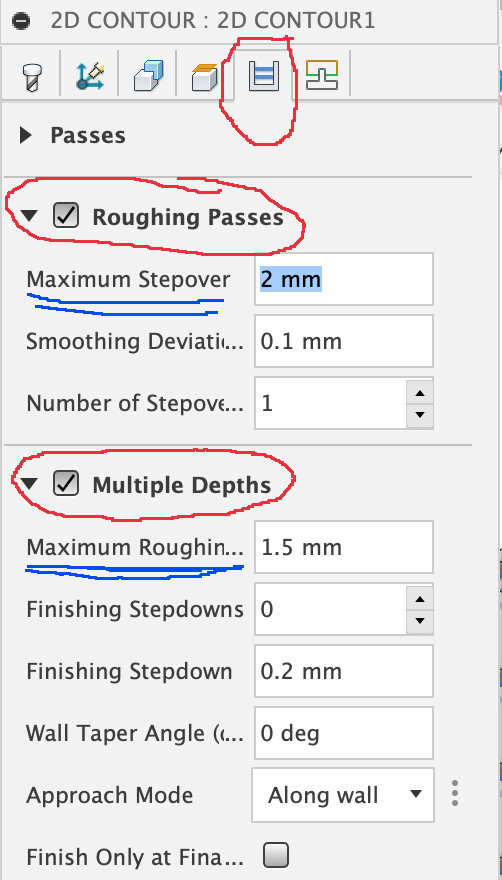
Next we want to look at the passes. What passes does is control how deep of a pass the tool takes. Fusion will for what ever reason make a weird preprogrammed
depth pass of 13mm. The depth will break the tool if not the CNC itself. Taking light passes is a good idea as it saves the tool from damage as well as less strain
on the spindle. Here we want to take a rough-pass somewhere between 3mm and 2mm. Professionally speaking 2mm Rough-pass/step-over on the High-Z CNC is a good to get
started with when milling multiplex plywood. Softer woods like pine or popular could be cut at at 3mm or more. But for a beginner I really can#t strain the
important of keeping the rough-cut pass to a maximum of 2mm.
Next select the multiple passes. Here set the passing depth to 1mm or 1.5mm. This lets the CNC know that it should take passes that are deeper no depth than 2mm.
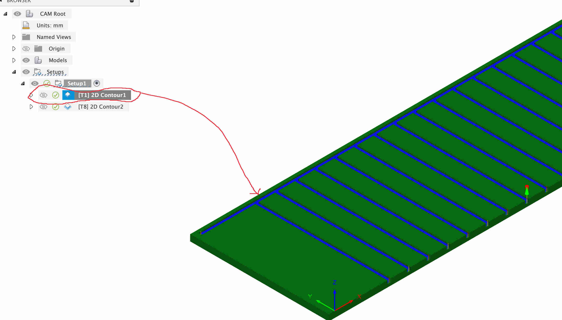
Each pass the tool does will have a depth of 1.5mm. Once you have added all of these setting click ok. Fusion will now create tool path. The result should end up
looking something like this in the screen shot on the right. In this image you will also notice that I have already added the second contour. Let have a closer
look at the setting here.
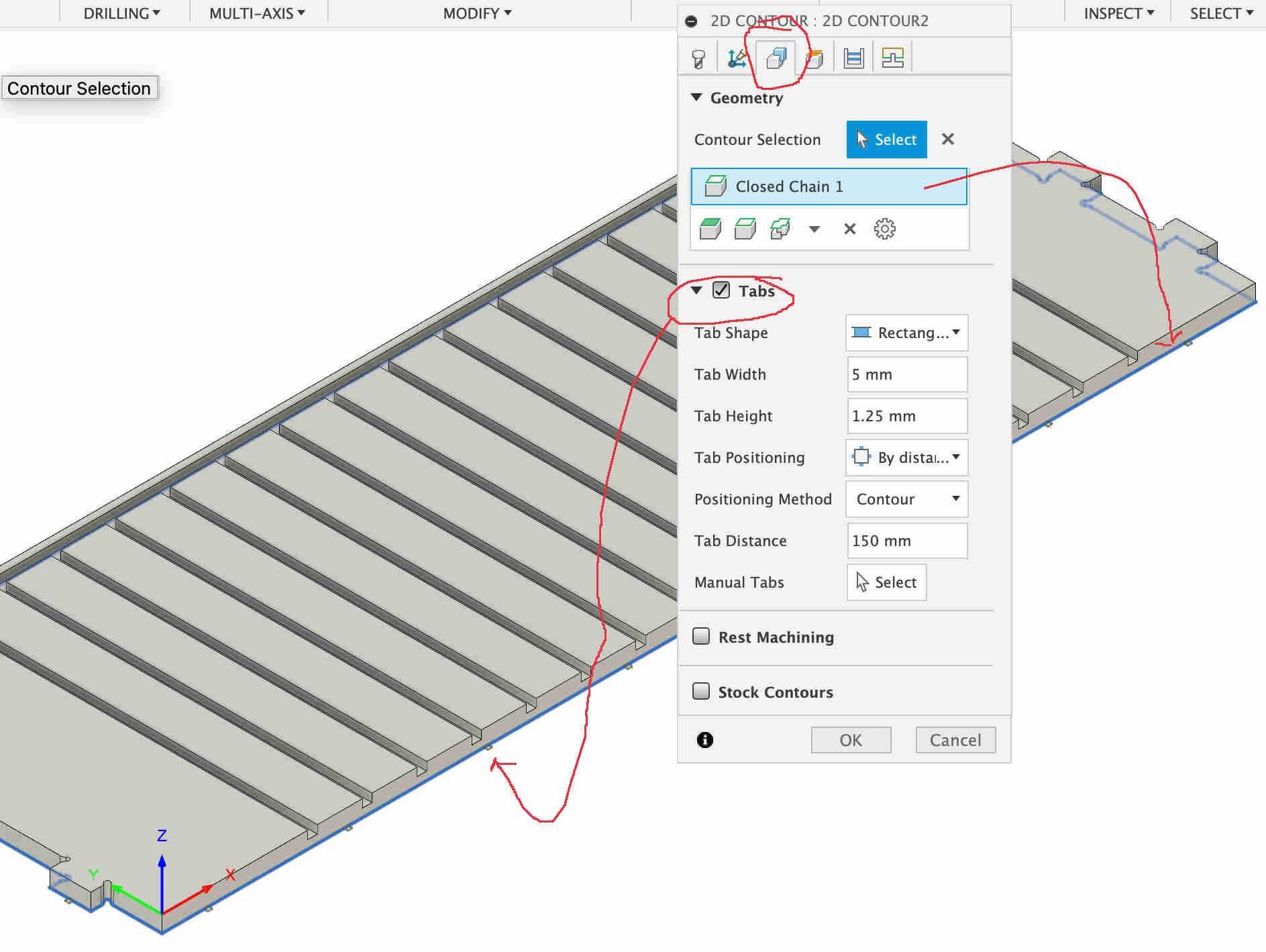
With the second contour which goes along the outside of the board, we want to add tabs. Tab are there to keep the workpiece from coming loose when making the final milling pass. We do not want the piece to move at all. As it could come flying out or even jamming the CNCs tool path. Create a new contour, select all the same setting as before. Than go to Geometry select the outer bottom contour, should be highlighted in blue. Check the Tabs menu. I usually just adjust the distance between the tab till I am happy with how it looks. The second options manually selecting the ones you want to keep or selecting the them where you would like them to be placed.
simulation of the CNC code
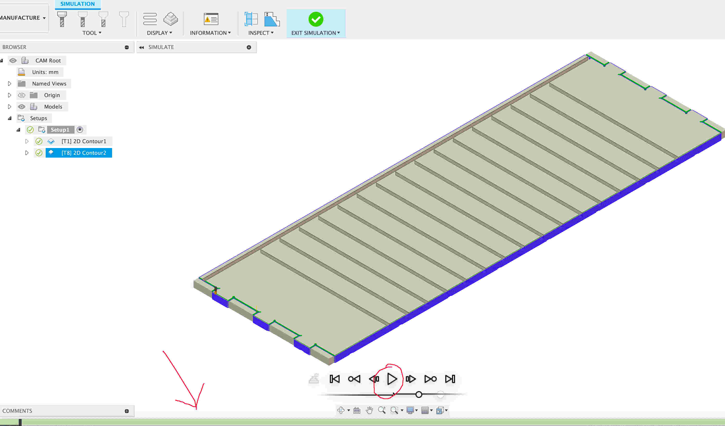
To check and make sure that the code is doing what it should, we can simulate the CNC. To do this right click on the contour you would like to have
simulated. In the pop up menu select the simulate function. Once in the menu you will see a play button, at the bottom of the screen there is also
a green bar. In this green bar, if an mistake or errors show up they will be displayed as small red bar. Most likely there could be interference
of the tool and the workpiece. In this case we have a full green bar which means we don't need to fix any issues. If there are any problems that
show up, we exist the simulation and right click on the contour and select
To change any setting or simulate right click on the contour or feature that you may wan to have a closer look at.
I have highlighted the three menus that you will be using the most in the left image below.
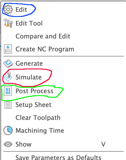
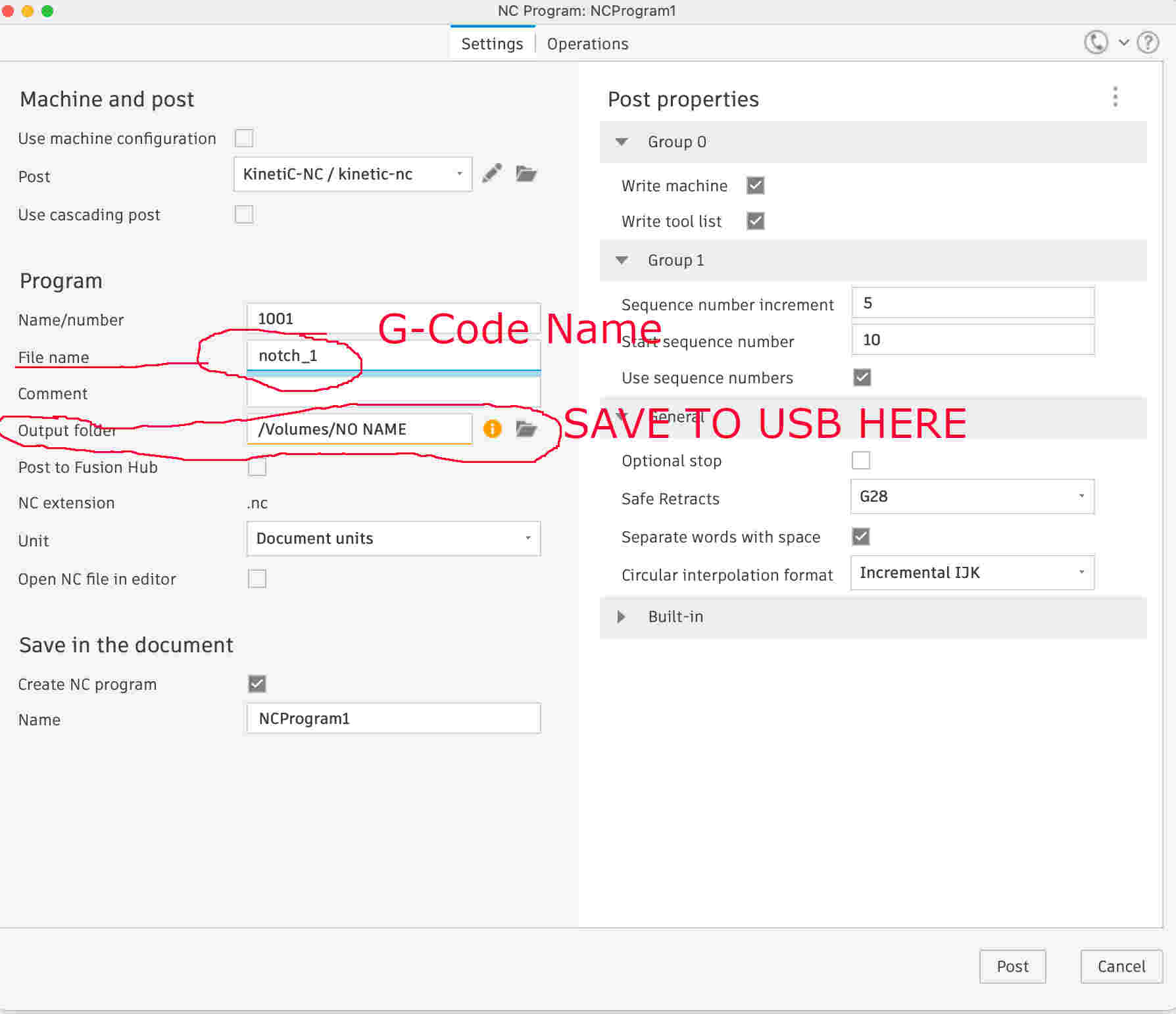
The next thing we want to do is post process the G-code to a USB. Here we want to right click on the contour again and select Post process.
Here we can name the file, recommendation would be name the code after the contour or feature you want to machine, and as there are more then
one machining process also add a number to the name. Letting you know which one of the contours you wanted to mill first.
How the CNC High-Z works and functions
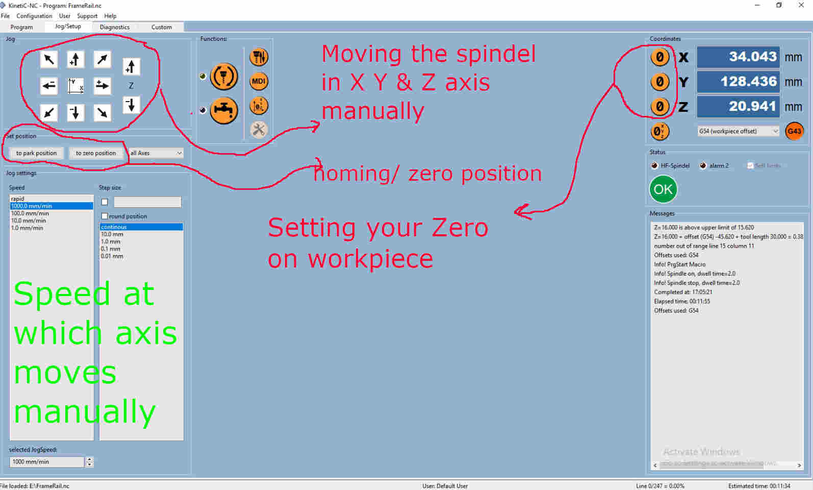
The High-Z works with a program called Kinectic NC. This software Communicates with the CNC mill. Looking at the Jog/set menu, you will notice a that it
that here you can move the X, Y and Z axis. This allows you to move the spindle into position so that you can change the tool, setup your Zero positions
and it also lets you home the CNC. When first starting the CNC it will ask if you want to home it? I would recommend this as it let the CNC find its location
and gives it chance to calibrate. This should always be done even after setting up and before run the G code. Below is a screen shot showing all the functions
located on the jog and setup window.
Setting the up the CNC
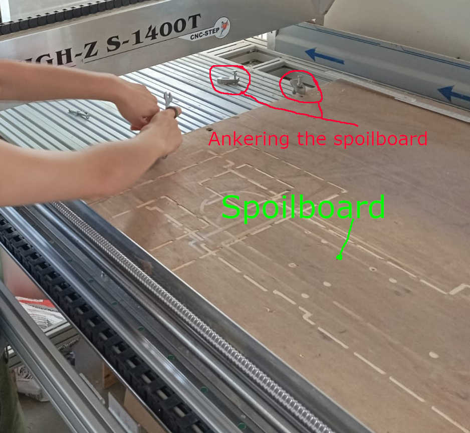
At this point we are almost ready to use the CNC. The only thing stopping us from continuing is that we have to add a spoil-board on the bed of the CNC. What is a spoil-board. A spoil-board insures that we avoid running a milling tool in to the bed of the CNC. This does take away from the overall height that now can be milled. The spoil-boards is usually a cheap plywood or old MDF material where if you cut through your workpiece you can cut just a little deeper to insure that the workpiece can be cut out and removed with minimal effort. The spoil-board is anchored to the bed of the CNC, using brackets, here highlighted in red on the image below. You can also notice that the board has be used before a spoil-boards, as the markings of of where the CNC had cut through other pieces.
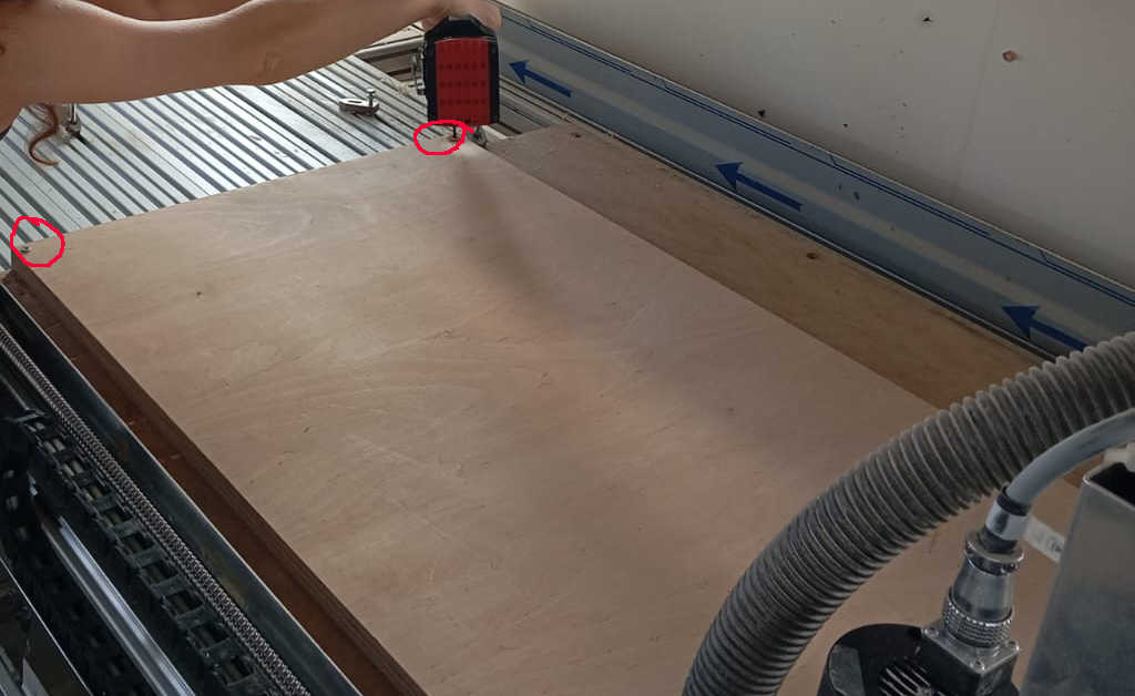
Once the spoil-board has been added, you can now go ahead and add the workpiece that will be milled. To do this we first cut the board to size. When cutting the workpieace to size add 15mm to 20mm to the size. This will give you a good place to add some screws or other fasteners to keep the workpiece in place. When doing this make sure to place so that they do not interfere with the milling bit. Running into a screw will damage the milling bit. Second thing to watch for is that the tool will clear any parts that are design to hold spoil-board or workpiece in place. Incase of holding down the workpiece the more spots you can tighten down the better the if anything happens to loosen up. In the image below you can see that screws were placed to hold the workpiece down. This was done in 4 conners. On the photo you can see how we did this.
Setting up the Z-axis
To setup the Z-axis there are sensors out there that can be used like we explained in the group assignment.
But there is another method, using a sheet of paper. This method is just as good as setting the Z axis zero with a sensor. By jogging the Z downwards we place a
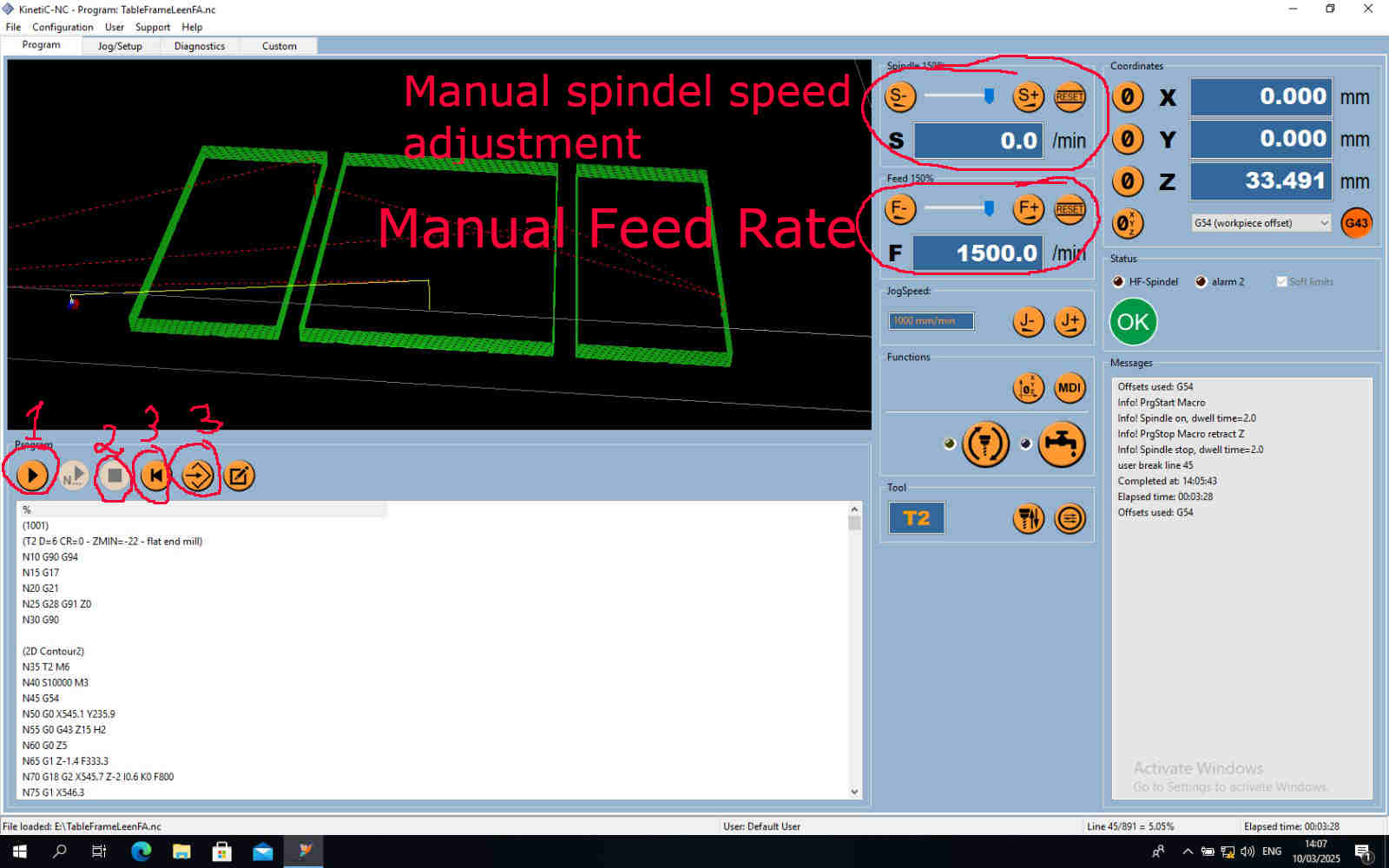
sheet of paper under the milling bit. But before we plug right into the workpiece, set the speed ( highlight in green writing in the image above) setting it 100 min/mm once
the mill get with in a couple milometers, change the speed again to have a the lowest setting speed. Moving the sheet of paper till the piece catches on the mill. That is
the perfect setting. Important to remember is that the speed you have set is also now going to be the homing speed of the Z axis. Before you set the Zero set the speed
to the 1000 min/mm. Now go ahead and click the Zero button on the right side.
Now go to the Program window, once all the setups have been completed. Here is a check list:
If you have done all of these check point above we can go to the the Program window. Looking at the image below the 1st button is the run function and will start the CNC milling process. 2nd button is the stop function, this will stop or pause the milling process. This would be used if you have an issue with the CNC or the code, also if you need a break or have to leave the CNC. 3rd button lets you rewind in case you had an emergency stop or you want to run the same code again if you are making the same cut again. 4th button let you load the G-Code from USB that you have created using fusion 360.
Conclusion
At this point, there are several important observations to make regarding the use of CNC machines. Speaking from the perspective of someone with many years
of woodworking experience, I can say that this particular project could have been completed more quickly and efficiently using a router and a table setup.
While one might argue that a CNC is a versatile tool that can handle various tasks in a single operation, when evaluating the pros and cons of using a CNC
for one-off builds, the disadvantages tend to outweigh the benefits. In fact, even an amateur woodworker could have completed this task in less time and with
fewer complications than those encountered when troubleshooting CNC G-code errors.
For example, a simple hand router would not unpredictably plunge into a workpiece. Moreover, one significant drawback
of CNC machines is the potential for losing the Z-axis zero point if a step is skipped. On the other hand, professional
CNC machines often include safety features that alert the user when an error occurs, which is a valuable advantage.
Despite these issues, learning to operate a CNC can be a rewarding experience, and there are notable advantages. One key benefit is the ability
to replicate the same part consistently, which is highly advantageous in an industrial or production setting. For instance, if a batch of 250
identical cutting boards is required, a CNC would certainly justify its use.
However, if I were to invest in a machine for my workshop, I would personally recommend a laser cutter over a CNC.
A laser cutter provides the capability to create templates and jigs, which can then be used in combination with a hand router for similar
outcomes often with fewer complications.
Throughout our experience, Leen and I faced several technical difficulties,
most notably the CNC performing unpredictable actions such as plunging into the material even after successful dry runs without the milling bit installed.
To address these issues, I conducted extensive research and found numerous user reviews describing similar problems. Ultimately, we discovered an effective
solution: after setting the X, Y, and Z axes, it is essential to "home" the CNC using its built-in homing function to return it to its park position.
Performing this step resolved issues related to random plunging and axis misalignment.
In conclusion, while CNC machines are undoubtedly powerful tools with significant applications, especially for mass production,
I must be candid in stating that, as my father wisely advised during my machining apprenticeship, parts should be made by hand
for runs up to 1,000 units. Only when producing 1,001 or more does a CNC become a truly cost-effective and time-saving solution
at that point, the machine starts generating profit rather than causing losses.
My Computer Storage project
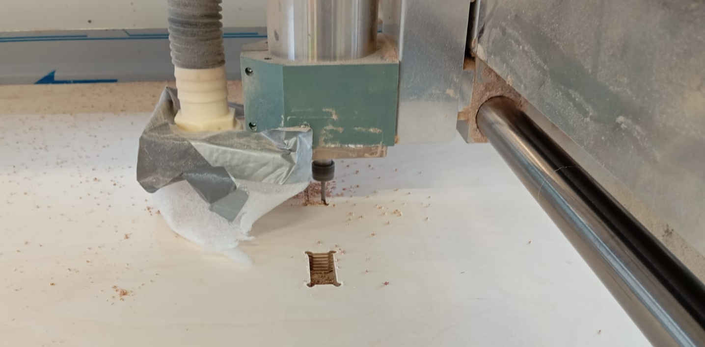
At this point and time I have finished milling two parts. This is mainly due to the fact that the CNC is not fast and I have to wait in line for my turn. It should be done in the next weeks. The back wall with the Hex patterns and one of sides is done. Here are the images of the parts on the CNC. The parts themselves are 1200mm long. There for with this CNC I recommend looking where the max travel for the spindle is and making sure that the part can be cut out any issues. To test this I ran the out line cut with the Z axis set higher than the workpiece making sure all points can be reached. This also helps to check of the code you are planing on using wont do something funny that would destroy the CNC or the material.
First cut
Almost done with the side
The final pieces
The next step of the build was needed here once again the material was cut to length, making sure that as little was wasted. The material was placed
on the CNC bed. The following was going back in to fusion to check all parameters for the CNCing the top and bottom. The part here called for a tool
change. The Finger joints where designed to avoid having to use the drilling function with would have added up once again in time as on this CNC
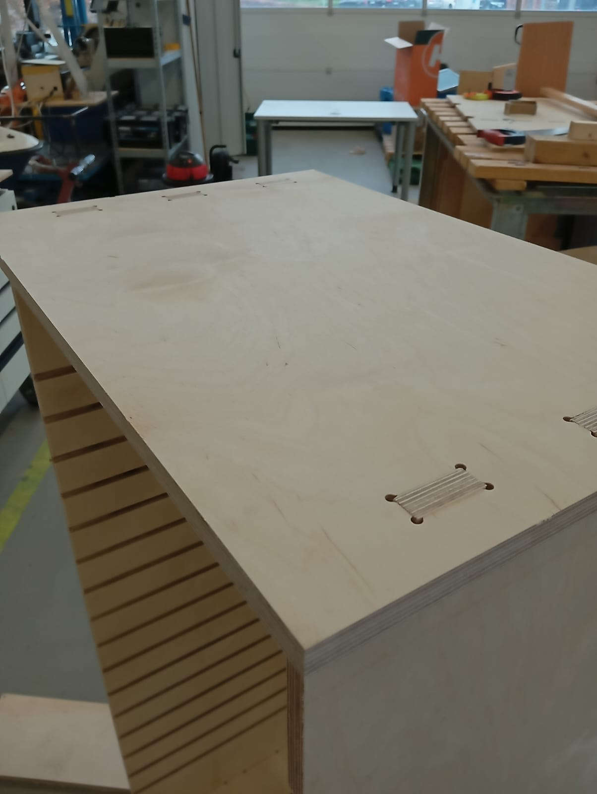
the tool change is manually done. The called for the bone type joint, so called as it looks like a bone, I made sure that it could be all cut out with
a 4mm diameter single flute mill end could be used. Leaving me with a single tool change to cut the back pocket and cutting out the part of the material.
Here you can see what a bone joint connection looks like.
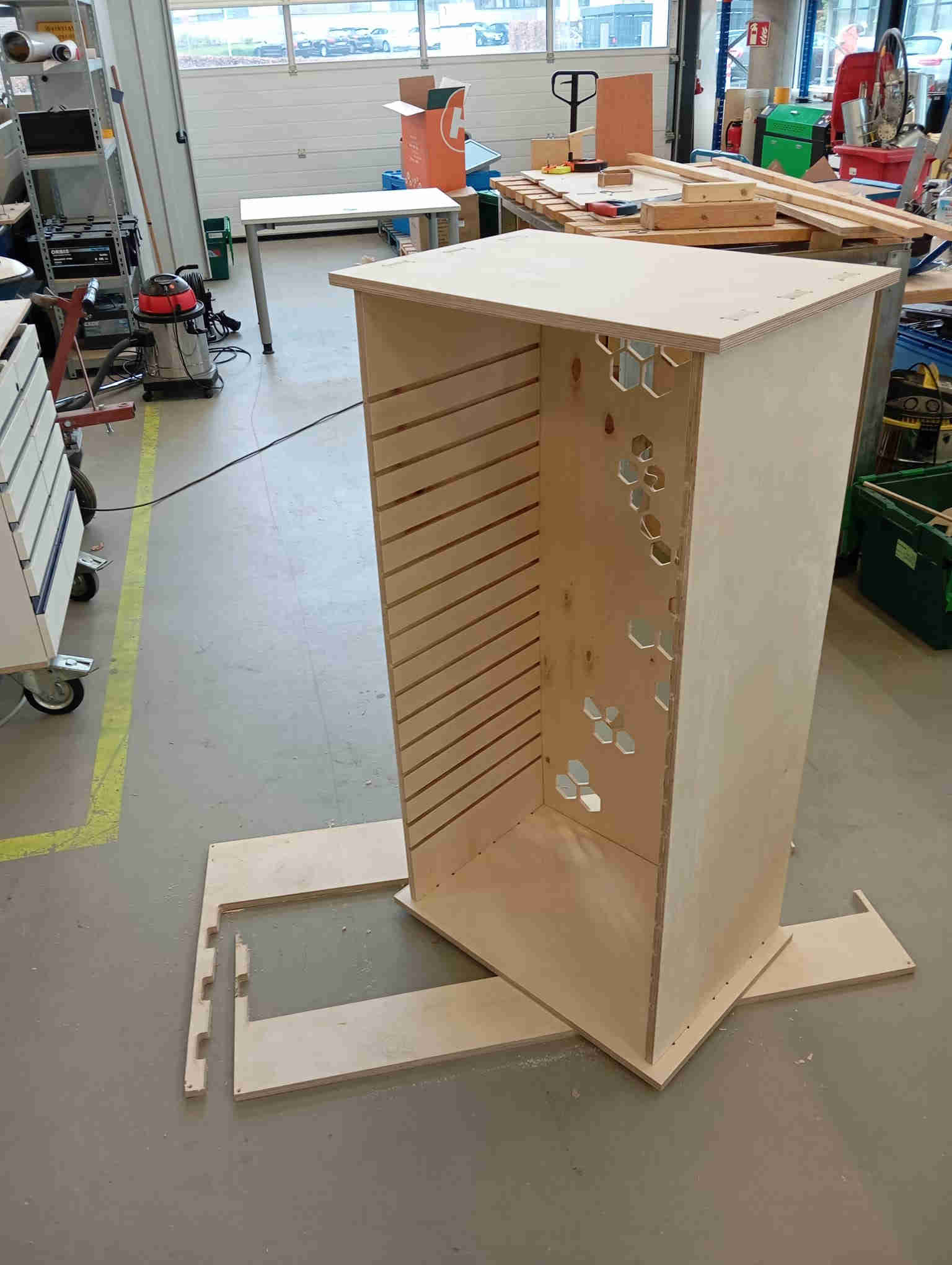
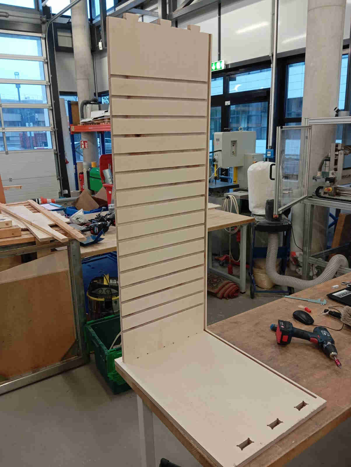
As the CNC is now cutting the last part, I finally got start placing all the parts together. The joints needed a little help to
squeeze in to the container part. I than added the back wall which I find to be the nicest part of the whole build.
Hero shots
