11 - Networking & Communications
This week, it was interesting to learn that there are so many different ways micro-controllers can communicate with each other, ranging from USB to Wi-Fi,
Bluetooth, I²C, and more. In our group assignment, we used Wi-Fi and I²C. You can read more about how our two projects communicated with each other there.
We also went a little deeper in explaining how I²C works. Here, I’ll give a simple explanation of how I set up my PCB to communicate with another Raspberry
Pi Pico W using I²C to display a relayed message entered in the IDE's serial monitor. This method can also be used to display information from a load cell
via a relay connected to a master micro-controller. The master then sends this information to the secondary micro-controller, which in turn sends it to the
OLED display. This setup means the master micro-controller runs a program that collects input data and prepares it to be sent to the secondary micro-controller.
Let’s take a quick look at what I²C stands for: I²C means Inter-Integrated Circuit.
As stated above the main propose of this is to have multiple boards communicate with each other. They way that these boards talk to each other is over
two wires. One wire is called clock signal (SCL), this helps the boards synchronize with each other. Reason to have the boards keep synchronized is to make them
work as one. This helps each of the boards to know what signal is being sent. It is a kind of heart that keeps time so that codes can be executed without issues
such as timing of when to send and receive data. The second wire called data (SDA) which can either send or receives the send information.
How to I2C
I2C is fairly simple to setup. The first thing you want to do is open up the data-sheet
to the boards you want to use. Looking at the data-sheet we can see that the pins needed on the master micro-controller are: GP2, GP3. GP4 is the SDA
Data cable which needs to be connected to GP4 on the secondary boards also known as the secondary to the Master. The second wire GP5 is the clock (SCL) which synchronizes
the master and the secondary micro-controller. Now the next wire that you could connect is the ground (GND), but if you are running the boards off then master boards.
Here I choose to run the boards on two different power supplies via USB cable.
Now that the two boards are connected there is still the matter of having some kind of read out that the message sent was getting through to the secondary. For this
part of the task, the use of a OLED display unite came in handy as here I2C could be used as well. Back to the data-sheet and we find that are available are
GP4 and GP5. As the display needed power as well GND and VCC can be connected to 3.3V out and any GND available. The display is
the under dog here of the secondary micro-controller and follows the orders to display what ever information was send from the primer source the Master micro-controller.
Master code
The code for the master micro-controller needs the following information, which pins will be used, every I2C connection needs a defined address, and
a serial monitor input. The pins were discussed above and need to be defined in the code. Here they were all teh default pins. One of the more
important information that is needed is that each I2C connection has a address. Each one of these I2C needs a unique address, which is done by
adding this bit of code #define Secondary_ADDR 0x10. This helps the Primary micro-controller to talk with the secondary micro-controller
using these lines of code Wire.beginTransmission(secondary_ADDR); Wire.write(...); Wire.endTransmission();.
As the Master micro-controller also needs to get some kind of input and the fastest way to do this to see if everything works as planed. The serial
monitor function can be used to send data to the master to send to the next micro-controller down the chain of command. This done by
add the next couple lines of code if (Serial.available()) {inputText = Serial.readStringUntil('\n');...} to the code. This
lets the person interacting with the PC using the IDE send a message. Looking at the code down below all of these lines were
add. At the top of the code to help with recreating this setup is a description on how the two boards are connected letting them talk to each other.
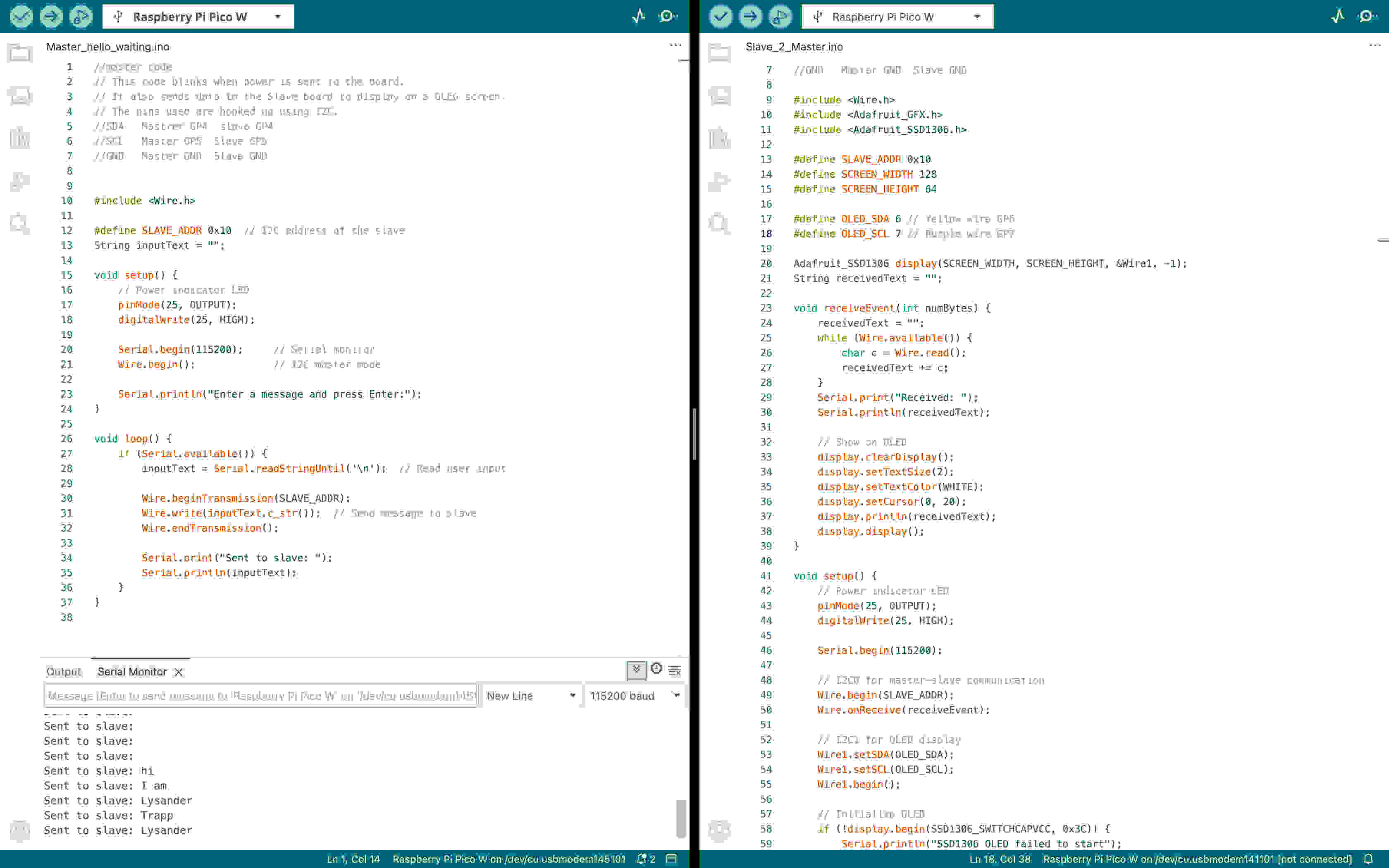
//master code
// The full description can be read in the text above.
// It also sends data to the secondary board to display on a OLEG screen.
// The pins used are hooked up using I2C.
//SDA   Master GP4	 secondary GP4
//SCL	Master GP5	secondary GP5
//GND	Master GND	secondary GND


#include Wire.h

#define secondary_ADDR 0x10  // I2C address of the secondary
String inputText = "";

void setup() {


    Serial.begin(115200);     // Serial monitor
    Wire.begin();             // I2C master mode

    Serial.println("Enter a message and press Enter:");
}

void loop() {
    if (Serial.available()) {
        inputText = Serial.readStringUntil('\n');  // Read user input

        Wire.beginTransmission(secondary_ADDR);
        Wire.write(inputText.c_str());  // Send message to secondary
        Wire.endTransmission();

        Serial.print("Sent to secondary: ");
        Serial.println(inputText);
    }
}
Secondary Code
As mentioned in the description a second Pi Pico W is needed. This board has to main functions, to receive code and transmit the message or information
to the OLED screen via I2C. The code tells the pico to basically listen for data being sent from the address >0x10. To do this
the following lines need to be added to the code Wire.begin(secondary_ADDR);. Once that data is receive the code
Wire.onReceive(receiveEvent); tells the code that data has been receive lets the code move on to the next command.
The step in the line of commands is to let the boards know what bus we are using. Here are two different jobs that the board has to complete.
This means that the one job needs to be split into two different jobs. Wire.begin(...) // I2C0 — for communication with master
is using GP4 and GP5 which are the default pins used to have the two boards talk to each other, telling that they are either waiting o data or that they
have received data. To be able to display this, the second job is that to let the board know where to send this information. For the Pi Pico
to do this the command line Wire1.begin(...) // I2C1 — for OLED display is needed. Wire1 also has a different set of pins which
are called GP6 and GP7 which if correctly hooked up to the OLED will relay the message to display so that the human interface can
see that the information has arrived.
This also means that the libraries have to be added to you IDE. The libraries used here are Adafruit_SSD1306 and Adafruit_GFX. This
initializes the OLED allows it to display text and clears it when new data is sent from the master to the secondary to the OLED. This is the code
in it most simplest form.
	//secondary code
	// This code blinks when power is sent to the board.
	// It also sends data to the secondary board to display on a OLEG screen.
	// The pins used are hooked up using I2C.
	//SDA   Mastrer GP4	 secondary GP4
	//SCL	Master GP5	secondary GP5
	//GND	Master GND	secondary GND

	#include  Wire.h
	#include  Adafruit_GFX.h
	#include  Adafruit_SSD1306.h

	#define secondary_ADDR 0x10
	#define SCREEN_WIDTH 128
	#define SCREEN_HEIGHT 64

	#define OLED_SDA 6 // Yellow wire GP6
	#define OLED_SCL 7 // Purple wire GP7

	Adafruit_SSD1306 display(SCREEN_WIDTH, SCREEN_HEIGHT, &Wire1, -1);
	String receivedText = "";

	void receiveEvent(int numBytes) {
		receivedText = "";
		while (Wire.available()) {
			char c = Wire.read();
			receivedText += c;
		}
		Serial.print("Received: ");
		Serial.println(receivedText);

		// Show on OLED
		display.clearDisplay();
		display.setTextSize(2);
		display.setTextColor(WHITE);
		display.setCursor(0, 20);
		display.println(receivedText);
		display.display();
	}

	void setup() {
		// Power indicator LED
		pinMode(25, OUTPUT);
		digitalWrite(25, HIGH);

		Serial.begin(115200);

		// I2C0 for master-secondarycommunication
		Wire.begin(secondary_ADDR);
		Wire.onReceive(receiveEvent);

		// I2C1 for OLED display
		Wire1.setSDA(OLED_SDA);
		Wire1.setSCL(OLED_SCL);
		Wire1.begin();

		// Initialize OLED
		if (!display.begin(SSD1306_SWITCHCAPVCC, 0x3C)) {
			Serial.println("SSD1306 OLED failed to start");
			while (1);  // Stop here if OLED fails
		}

		display.clearDisplay();
		display.setTextSize(2);
		display.setTextColor(WHITE);
		display.setCursor(0, 20);
		display.println("Waiting...");
		display.display();
	}

	void loop() {
		delay(100);  // Nothing to do in loop
	}
Hero shots of the setup and code working
Here is a screen shot of the text that was entered in the serial monitor, sent to the Master micro-controller sent to the secondary sent to the
the OLED display screen. The photos will also show the wiring setup as described in the the text and code. I2C is nice to send informational data over
short distances. If longer ranges are need it would make more since to use wifi or other ways of transmitting data. For example in the group
assignment where one project sends information to another via wifi and than changes this information to be relayed by I2C.
You will notice that I have left out something in the code that you will need to add yourself. If you take a look at the code and the screen shot where
the #include libraries are the brackets known as great and less than have been left out. As the seem to have an issue working with HTML and blend out the
libraries.
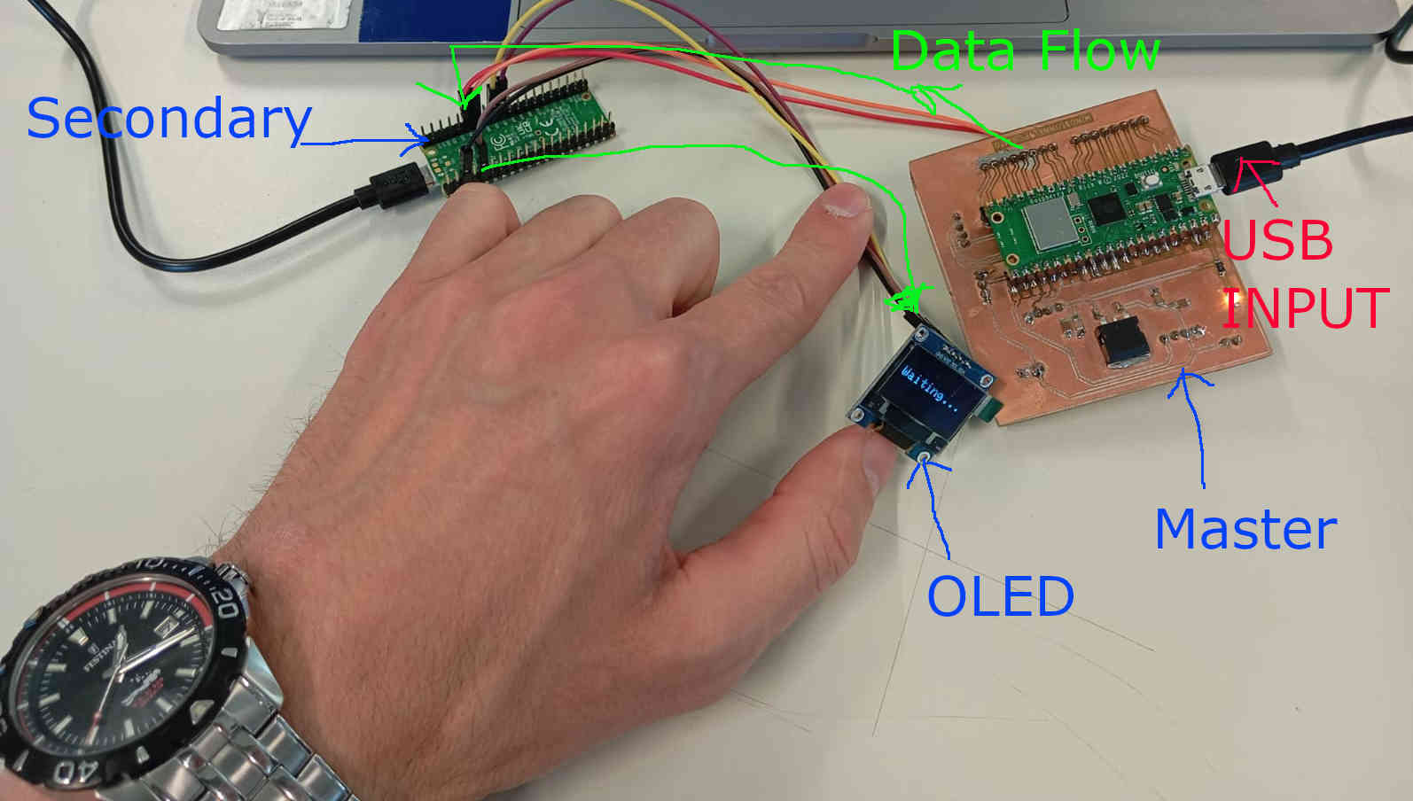
The image below shows how the setup is linked. The master being the micro-controller is the PCB that we made in electronic production week. The board gets information from the USB input cable that communicates with IDE serial monitor, where line of information here just a message from the human interface aspect writes a message. The master PCB will than relay this data to the the secondary which has sent a message that it is ready to receive the data. This is also displayed on the OLED. Once the data message has been sent this will than go through the secondary and be sent to the OLED. Below the image has bin labeled to making it easier to understand the how the work flow of communication works. Currently in the image the secondary is showing that it is waiting.
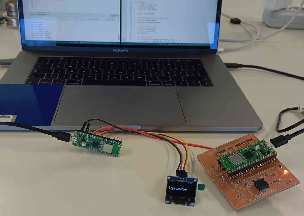
Let send some data. This does not necessary have to message that a human interface has to write out. If the code is changed it can display the input of a sensor for example. For this example I went ahead and just wrote a message to show that the theory of I2C works. Here I just entered the my name, Lysander.
Reflection on networking
This week I ran into one problem and just on monday I found how to fix this issue. The pi pico w seems to have a problem that it could not be found
by the ide and seems to have blocked itself off. This caused me to think that the micro-controller had broken some how, either by hooking up a
wire wrongly or just something broke with the board itself. This caused me to remove the board form the PCB. Doing this was not much fun, I ended up
breaking my PCB. The thing that happened on removing the Pi Pico W ripping off the copper pads. After re-milling the PCB and soldering the components
everything seemed to work again. Till the next day where the board would not be found again. Turning Raspberry pi Pico into a board that I find to be
flawed.
Later on one we found away for the board to work again. Now I know that holding the Reboot button should work. But it did not work for me with the use of the
IDE. What did help was downloading a file that nukes (Flashes) the board, a complete reset. Overall I am happy to have at least found a way to deal with this
issue. But as this a Reflection of this weeks networking and how to gather information form different boards that may gather information form other parts
of the house or even with in the same working area, I find this to be a good lesson on information gathering. It is scary to think how small of a board could
be created to spy on others. Not something I would recommend doing, but as a kid at heart kinda cool. At this point I do not know if I will use this on my
final project, as it seems that a stand alone wind tunnel does not need to have these functions. I will how ever use the OLED to display information
via I2C to show me the RPM (speed) of the fan or fans and for getting a read out of the force acting on the Load cell sensor.