02 Assignment CAD (computer aided design)
This week's main topic is CAD. There are many different ways to approach a technical drawing,
one of which is using a CAD system. This allows you to start with a simple 2D sketch and then
extrude it to the required dimensions.
To document this process, we also need to create a short video. Luckily, it doesn’t have to be
high quality—just a few seconds long. As before, we’ll include plenty of screenshots along with
explanatory text.
This weeks to-do list
Raster vs Vector
A raster image is any image made up of pixels, such as photographs or scanned drawings. Because raster images are pixel-based, they lose quality when resized or scaling them up results in pixelation. The second type of image is a vector image. Unlike raster images, vectors use mathematical paths, allowing them to be resized without any loss of quality. No matter how large or small the scale, vector images remain crisp and clear.
Raster images come in formats such as:
- SVG – Ideal for web use
- AI – Adobe Illustrator format
- EPS – Best for printing
- PDF – A universal format
Vector images are commonly used in:
In my last assignment, I created a tutorial on scaling and compressing images using GIMP. This time, I decided to explore
Inkscape,
a powerful vector graphics software. While it is primarily used for creating 2D drawings, Inkscape also allows for photo editing,
path tracing, typography design, and advanced object manipulation, making it a versatile tool for digital design.
Since I wasn’t sure what to draw or sketch, I chose a drawing I made back in 2023. I had previously shared this drawing
with a friend who is passionate about computer graphics, and he transformed it into a logo for me. Inspired by this, I
decided to convert it into a vector image, with the goal of turning it into an iron-on sticker for next week’s computer-aided
cutting assignment.Left after graphics artist, Right Original image by me.

How to convert a Raster Image to Vector Image
After watching a tutorial that explained the process I wanted to follow, I got started.
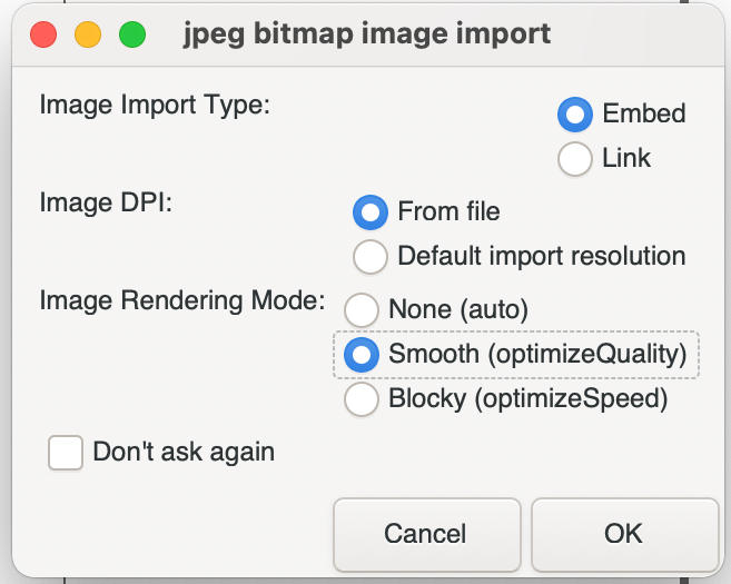
I launched Inkscape and imported the image I wanted to convert. Instead of using the Import Image option, I simply clicked and dragged the raster
image into Inkscape. When the Bitmap Image Import pop-up window appeared, I selected the "Smooth" option
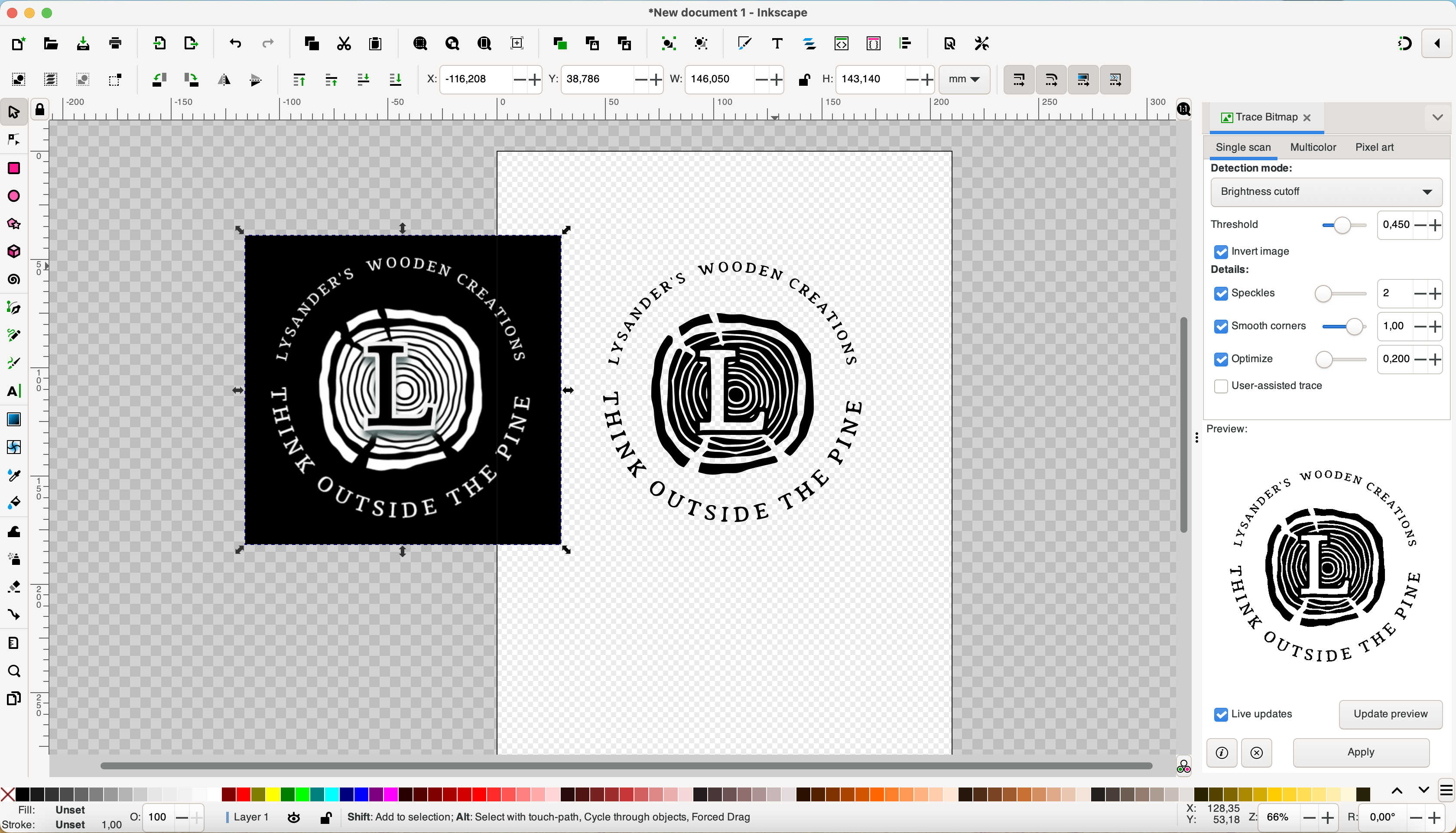
trace bitmape getting started
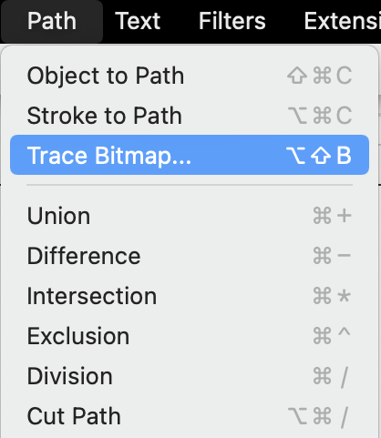
At this point, your image can be scaled to your preference using the arrows around the image or the toolbar at the top, where you can also adjust the X and Y axes. Next, I navigated to the toolbar menu at the top of the window and selected Path > Trace Bitmap.
Once you select Trace Bitmap, a toolbar should appear, or you will see the options open on the right-hand side of the screen.
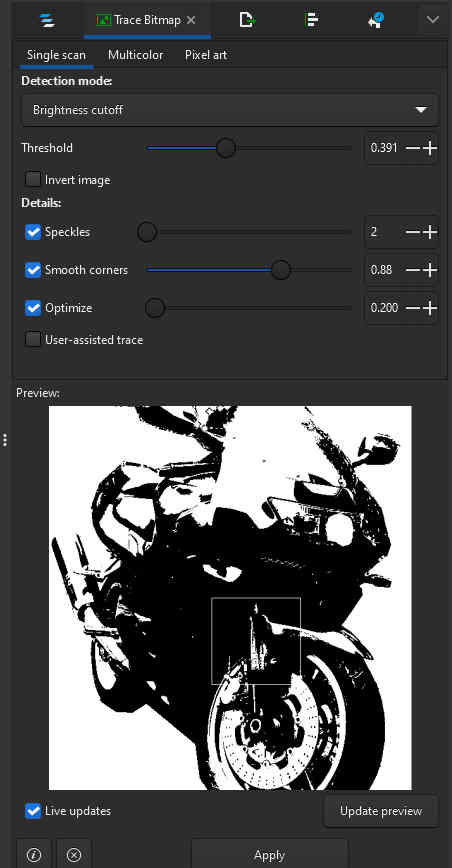
Here, you have the option to adjust the bitmap to your preference. Since my image was not multicolored, I chose the single scan option. This setting is particularly useful for tracing photo images. While it is possible to manually trace an image without this tool, it can be very time-consuming. I selected the invert image option and experimented with the details until I achieved a result I was satisfied with.
My final settings were:
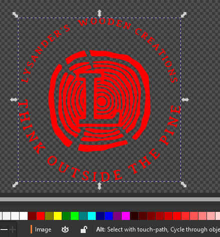
To preview the results, I enabled live updates, clicked update view, and then applied the changes. Next, I selected the original image, moved it to the side, and deleted it, leaving only the traced layer. At this point, I was also able to change the color of the vector image.
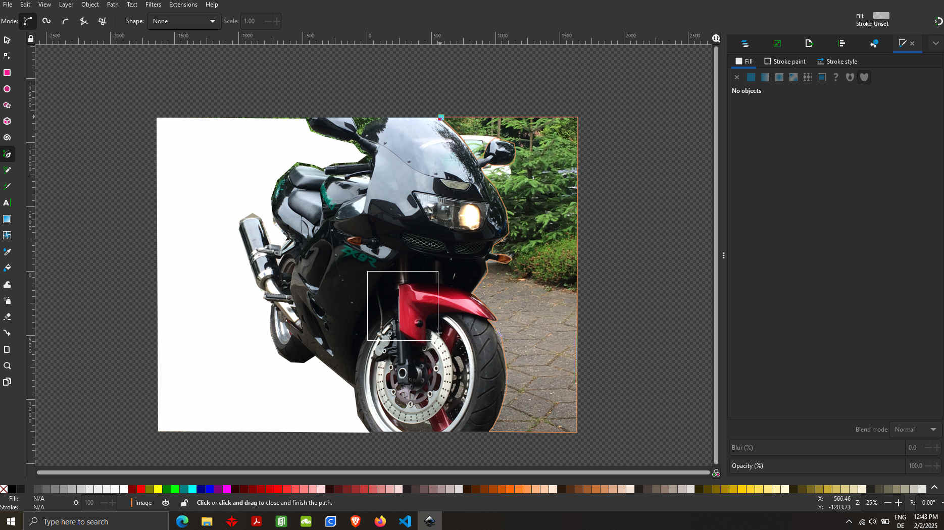
Now I applied it to photo using the same steps. Only that I know had to use an extra step to cut around the image using draw bezier curves and straight lines.

Which can be found on the left menu bar.
Tracing the outline of the image doesn’t have to be perfect, as the nodes can always be adjusted later. Once I was satisfied with the outlined image, I removed the unwanted layers and repeated the previous steps. If the cut didn’t work, an alternative method (a small workaround) was to take a screenshot, crop the image using GIMP, and then reopen it in Inkscape. As a final result, we have an image that can be used for printing on a shirt or engraving onto wood with a laser.
how to model in 3D
There are many different CAD systems out there, ranging from 2D to 3D, SolidWorks, FreeCAD, SketchUp, and many more. Growing up, I used to watch my father work on a large drawing board, creating countless technical drawings by hand. This traditional method is something I still enjoy from time to time, especially when designing furniture. I started learning digital drafting with 2D drawings in TurboCAD and later moved on to SolidWorks. Today, I can work with almost any CAD software. My favorites are Autodesk Inventor Professional, though I sometimes use Fusion 360 depending on the project.
Nowadays, there are also many free online CAD tools available, making it easier than ever to get started. Programs like FreeCAD, Tinkercad, and Onshape offer great options for both beginners and professionals who need quick and accessible design solutions. I will be sticking to my favorite CAD software, Autodesk Inventor. I find it easy to use and intuitive.
Using Parametric
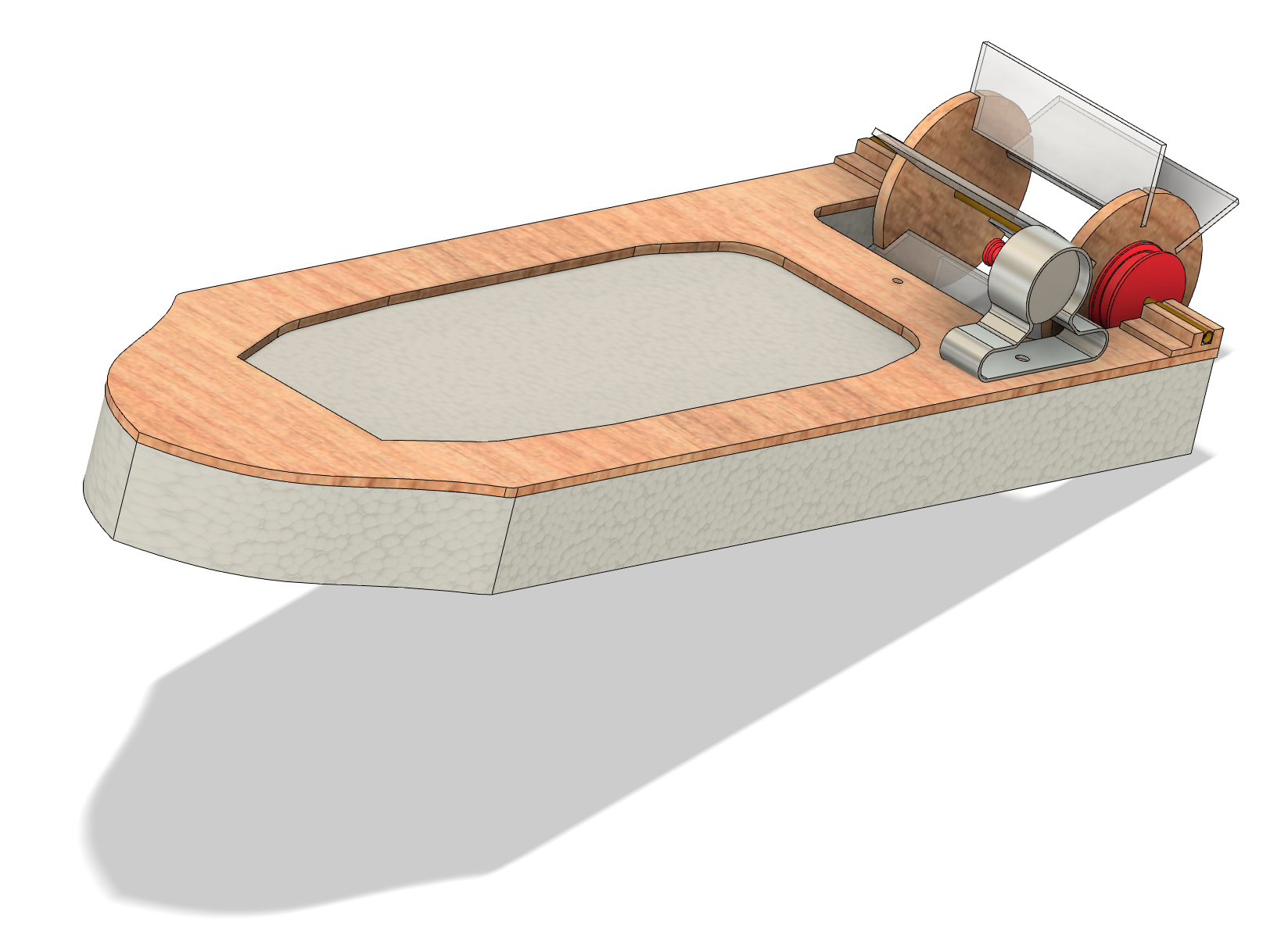
In my final project, I first created a sketch on paper to plan out the design. The project consists of several components, one of which is the main tunnel with a viewing window. The tunnel’s dimensions are as follows:
The viewing window will need to be inset by the thickness of the acrylic (3mm) to create a smooth surface inside the channel.
Setting up the parametric
Open the "Modify" menu in the top bar and select "Change Parameters." Once the menu is open, you can add your parameters by clicking the "+" symbol. Personally, I don’t give my parameters long, detailed names. I usually just sketch the design on paper and label the measurements as “a1, a2, a3,” and so on. But for this example, I’ve given the parameters more meaningful names. Parameters are especially helpful for complex parts like gears. With Inventor, parameters can import an Excel table with all your measurements.
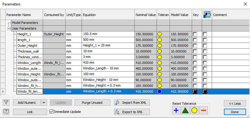
Here, you can see that I’ve entered the names based on the function of the parameter.
For more complex drawings, you can also do all the math for your parts directly in
the parameters, including adding tolerances. In the image below, you can see how the
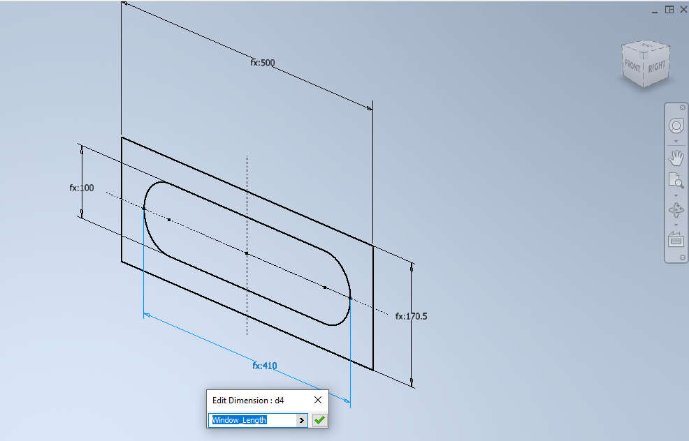
2D drawing looks once you have added the names of the parameters.
To create the slot, select the Slot function overall. This gives you the overall
length. The button looks like this: ![]()
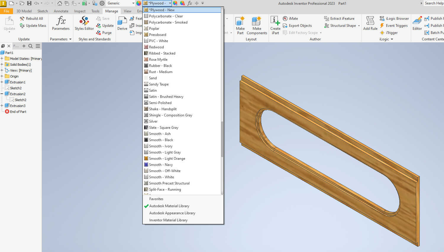
Next, extrude the body to 10mm and add the recess to set the window at a depth of 3mm. Include a tolerance of +0.3mm to give the window a little play, allowing it to just squeeze in. Repeat the slot function, add the dimensions, and select Extrude Cut. I also added a rabbet of 5mm by 10mm where the top and bottom of the tunnel can be glued together. For the next step, I wanted to render the 3D model to give it a realistic look. To do this, go to the top menu bar, click on "Appearance," and select the material you want to represent.
The Assembly Proccess
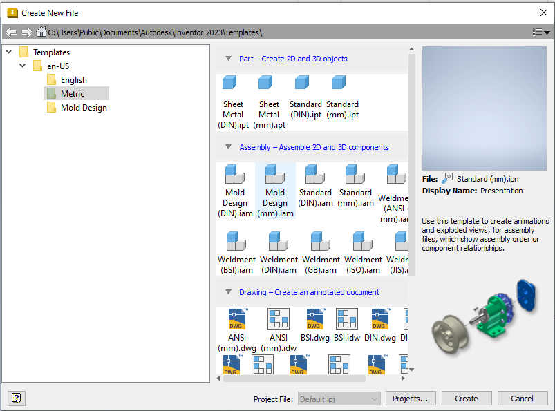
After I made all the parts, the tunnel needed to be assembled. This can be an easy process, but it can also be one of many challenges if you haven't done this task before. Therefore, I suggest watching this video tutorial. It will show you how to create joints that have movement, not just static ones. Every CAD software handles this task differently, and some do it better than others. In Inventor, you should have created a folder containing all your project parts. Doing this ensures all parts can be imported into the assembly functions. To access assembly mode, follow these steps: File > New. This window should appear below. Select the Metric folder, go to Assemble 2D and 3D Components, then select Mold Design (mm).iam and click Create.
importing parts
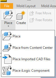
To import the parts go to menu select place part. Next select the folder in which you saved all the drawings.
This process can be repeated for every part you want in the assembly. If a part doesn’t fit,
you can go back to your main drawing and adjust the parameters or measurements by clicking
on Parameters or right-clicking to Edit Sketch.
Hint: If the part is very complex, it’s a good idea to rename the
sketches to make them easier to find.
Once the folder with the parts is open, select the part and place it as needed. Then, repeat the same
steps to add the part you intend to join to the other part.

Assembly
There are two types of parts: joints and static parts. Joints are generally made of multiple connections.
In this case, a joint connection is a movable connection. A static joint, on the other hand, does not move;
it only has its final position.
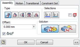
Here, we want to select the constraints  button under
the assembly menu on the top toolbar
(see image below). You will need to set several constraints to align the part correctly. This can be tested
by pulling the connected part in different directions. If the part moves in any way, it means there are missing
constraints.
button under
the assembly menu on the top toolbar
(see image below). You will need to set several constraints to align the part correctly. This can be tested
by pulling the connected part in different directions. If the part moves in any way, it means there are missing
constraints.
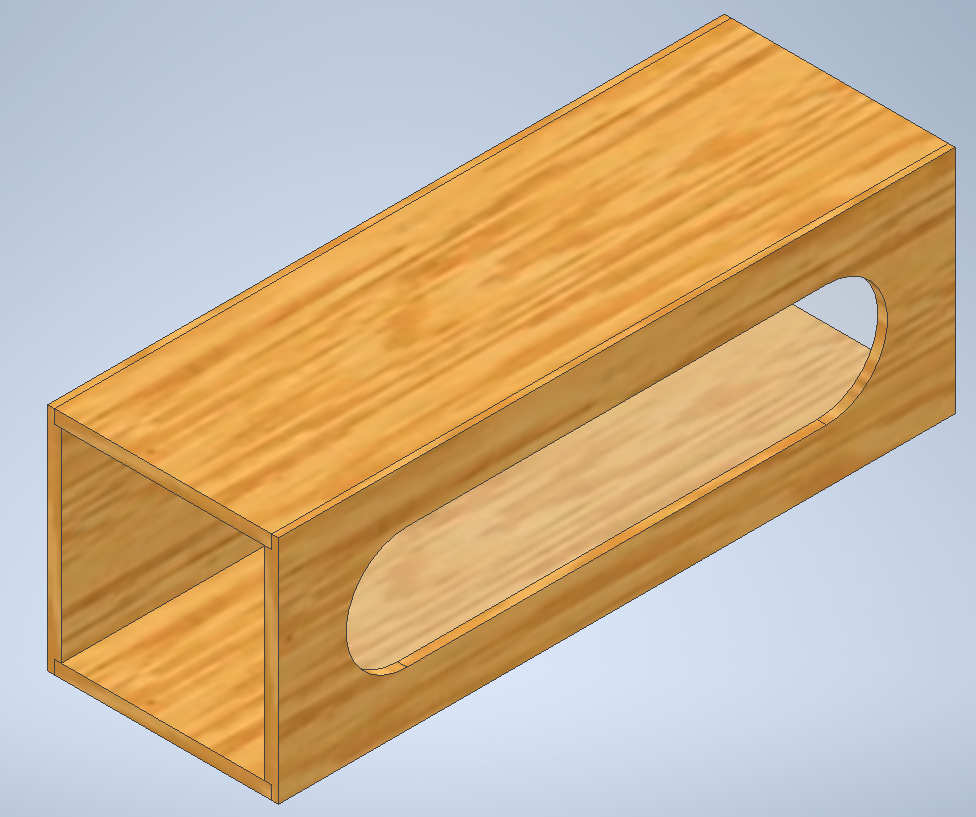
If everything worked out the parts will be assembled like in the image of wind tunnel.
Conclusion to 3D modelling
In conclusion, 3D modeling is a useful tool and skill to learn. The reasons for this are that it provides great access to designing and building parts or constructing machines. It allows you to visually check your designs and test for strain, especially if the part needs to support a load. It also helps you estimate the part's weight based on the material used. With the animation of the part and its joints, it becomes possible to test for interface issues and get an overall view of how the design functions. Inventor is a great tool for working with large assemblies, but when modeling individual parts, it is recommended to use software like Fusion 360.
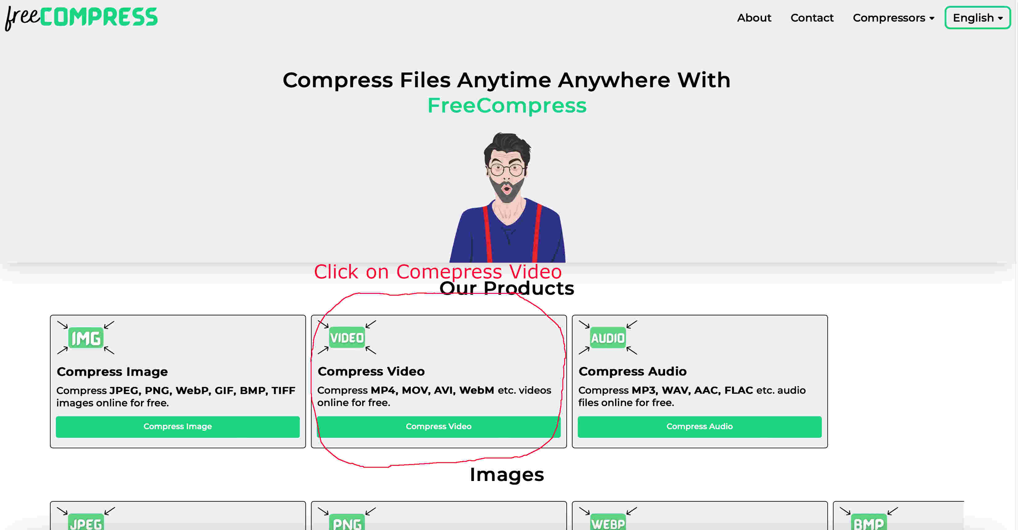
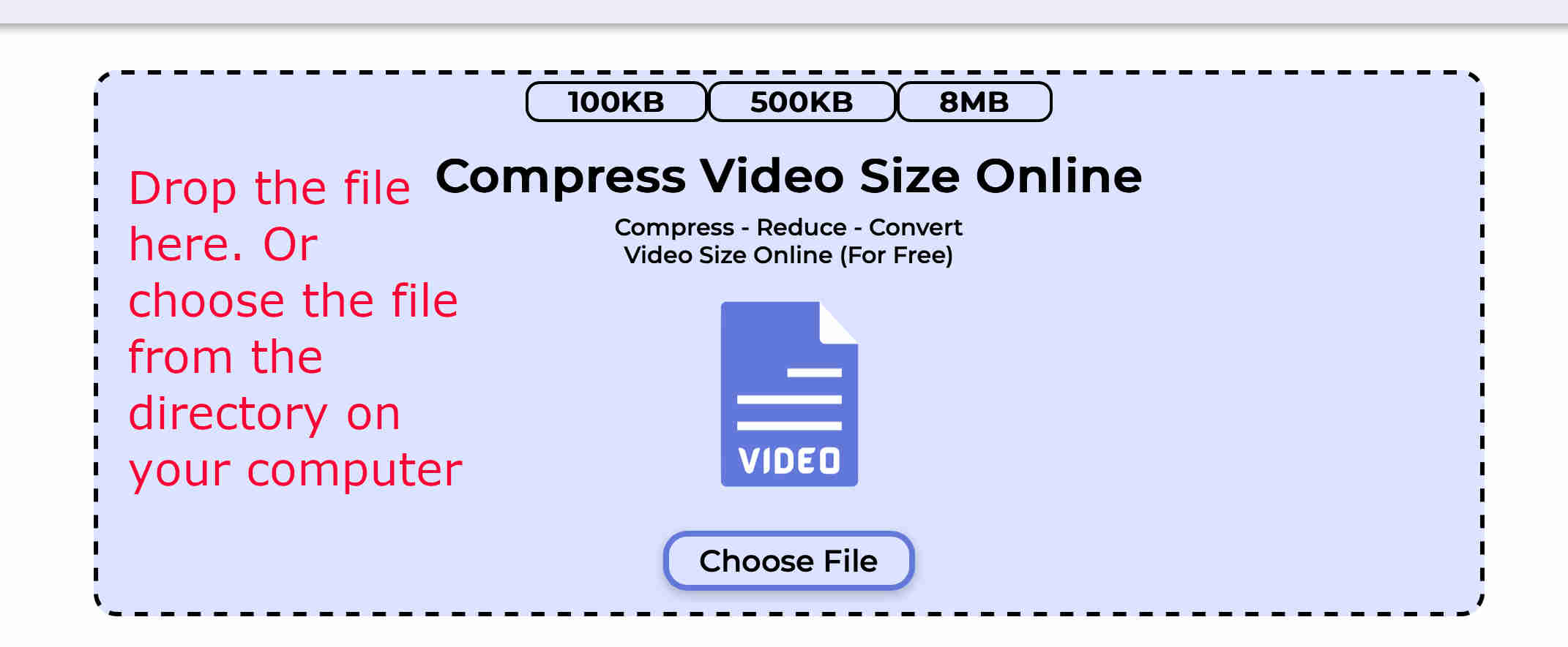
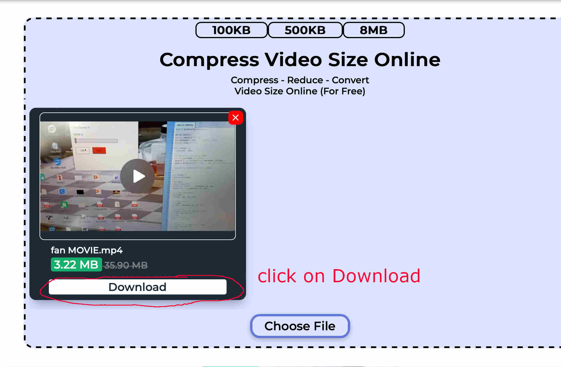
To download the drawing, please visit my final project page. On this page, you will find all the technical drawings related to the final project, as well as a video compression. The original video had 1.4MB the compressed version has 5KB. If you break that down the Compression Ratio = 1400KB/5KB= 280:1 Ratio. This is a massive compression, Which is really noticeable in the videos quality as it is 280 times smaller. To compress the video, I used an online video compressor. This is super easy with the online converter and compressor.Select the MP4, and after simply left click on the file you want to convert and drag and drop. Depending on how big the file is it will take a couple minutes. Once it is done just click download. In case you get stuck here are some images to follow:
I recorded the video a couple of days ago while 3D printing. It is only 20 seconds long.