Interfaces and Application programming
This week's assignment was:
- compare as many tool options as possible
Different Tools for Building GUIs:
1. Processing
Description:
Processing - Wikipedia is a Java based language and IDE for interactive graphics and visual arts. You use GUI libraries like ControlP5 to improve the sketches (canvas drawings).
Features
- Sketchbook IDE for organizing projects and auto translating sketches into Java classes.
- Real time interactivity with keyboard, mouse, cameras, and Arduino inputs.
- ControlP5 library offers buttons, sliders, toggles, textfields, charts, drop downs, ...etc.
Pros and Cons
- + Quick visual feedback, little complexity, useful for teaching coding, data visualization, and animations.
- - Isn't a general-purpose GUI toolkit because it doesn't have the form-layout managers and native widgets that desktop frameworks have.
2. Home Assistant
Description
Home Assistant - Wikipedia is an open source, Python based platform with a customizable dashboard and automation engine.
Features:
- Drag and drop dashboards with several card types (entities, gauges, graphs, ..etc.).
- Extensive integrations library (Zigbee, Z Wave, Matter, Nest, ..etc.).
- Rule based automations with triggers, conditions, actions and community blueprints.
Pros and Cons
- + Dashboards for uncommon devices, several card kinds provided by the community, simplicity, and complete automation.
- - Initial configuration requires YAML, can be bulky and expensive for non-home application.
3. Node.js + Electron
Description
Electron embeds Node.js + Chromium so you can build cross platform desktop GUIs with HTML, CSS, and JavaScript.
Features
- Web tech desktop apps, where they use single JS/HTML/CSS codebase on Windows, macOS, Linux.
- Desktop integration APIs, such as tray icons, global shortcuts, native menus, notifications, file drag and drop), ...etc.
- Node.js runtime in the main process for file I/O, networking, local code add ons.
Pros and Cons
- + Use web-development competence, have access to the npm packages, have a single codebase for Windows, macOS, and Linux.
- - Security issues with Chromium upgrades per-app, large libraries, greater RAM/CPU usage compared to native toolkits.
Python GUI
Description
Python GUI Library offers various GUI frameworks, such asTkinter, PyQt/PySide, Kivy, wxPython, PySimpleGUI, BeeWare, ..etc.
Features
- Tkinter built into standard Python: lightweight and no extra installation required.
- PyQt/PySide binding for Qt, which are rich, native looking widgets, designer tools, QML support.
- Kivy, which is a GPU accelerated, multi touch framework for desktop and mobile.
You can check out further widget tools here!
Pros and Cons
- + Wide range of selection; from simple (Tkinter) to professional (PyQt) to mobile/touch (Kivy).
- - API styles that are fragmented; license (commercial vs. PyQt GPL), different learning curves and community sizes.
MQTT
We opt for MQTT as Protocoll. So we just needed to publish something to a topic with the UI and the programm on the recieving end(Pi Pico 2 W) stays the same
Pi Pico 2 W Setup
We went with Mika's Board and changed the Code he did in Week 11. You can also find there how to setup MQTT in combination with HomeAssistant, which is used later in this Documentation.
                            #include <Arduino.h>
                            #include <WiFi.h>
                            #include <PubSubClient.h>

                            // WiFi-Credentials
                            const char *ssid = "ssid";
                            const char *password = "password!";

                            // MQTT Broker IP address
                            const char *mqtt_identifier = "TestClient";
                            const char *mqtt_server = "192.168.188.52";
                            const char *mqtt_user = "mosquitouser2";
                            const char *mqtt_pass = "mosquitouser2";


                            WiFiClient ppClient;
                            PubSubClient client(ppClient);
                            char msg[50];
                            char topic[50];
                            int value = 0;

                            void setup(void) {
                              Serial.begin(115200);

                              pinMode(22, OUTPUT);
                              setup_wifi();
                              client.setServer(mqtt_server, 1883);
                              client.setCallback(callback);
                            }

                            void setup_wifi() {
                              delay(2000);
                              // We start by connecting to a WiFi network
                              Serial.println();
                              Serial.print("Connecting to ");
                              Serial.println(ssid);

                              delay(500);

                              WiFi.begin(ssid, password);

                              while (WiFi.status() != WL_CONNECTED) {
                                delay(500);
                                Serial.print(".");
                              }

                              Serial.println("");
                              Serial.println("WiFi connected");
                              Serial.println("IP address: ");
                              Serial.println(WiFi.localIP());
                            }

                            void callback(char *topic, byte *message, unsigned int length) {
                              Serial.print("Message arrived on topic: ");
                              Serial.print(topic);
                              Serial.print(". Message: ");
                              String messageTemp;

                              for (int i = 0; i < length; i++) {
                                Serial.print((char)message[i]);
                                messageTemp += (char)message[i];
                              }
                              Serial.println();

                              Serial.print("Changing output to " + messageTemp);
                              if (messageTemp == "ON") {
                                digitalWrite(22, HIGH);
                              } else if (messageTemp == "OFF") {
                                digitalWrite(22, LOW);
                              }
                            }

                            void reconnect() {
                              // Loop until we're reconnected
                              while (!client.connected()) {
                                Serial.print("Attempting MQTT connection...");
                                // Attempt to connect
                                if (client.connect(mqtt_identifier, mqtt_user, mqtt_pass)) {
                                  Serial.println("connected");
                                  // Subscribe
                                  client.subscribe("home/switch1");
                                } else {
                                  Serial.print("failed, rc=");
                                  Serial.print(client.state());
                                  Serial.println(" try again in 5 seconds");
                                  // Wait 5 seconds before retrying
                                  delay(5000);
                                }
                              }
                            }

                            void loop() {
                              if (!client.connected()) {
                                reconnect();
                              }
                              client.loop();
                            }
So what the code does, it connects to the WiFi and our MQTT Broker and listens to the Topic of the switch. If there is a "state change", the Pi Pico recognized it, because we subscribed to the channel and it turns ON or OFF the LED, which was connnected to Ground and GP0 on Mika's Board, acording to the Commands.
Processing
libraries
To see how you import libraries through the library-manager take a look at Mika's documentation. There is also a small explanation on what ControlP5 is.
we used the following libraries in our sketch:
- ControlP5 by Andreas Schlegel
- Mqtt for Processing by Joel Gaehwiler
The MQTT library, allows us to connect to a MQTT Broker, and publish and subscribing to topics.
the code
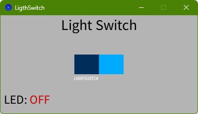
What does the Code? The code first connects to our MQTT Broker in a second/parallel thread to help reduce time with drawing the GUI and Connecting to MQTT. After that with the help of the ControlP5 library, the Switch was created. If the switch is flipped, the state is switched and send to the Topic "home/switch1". The states are ON and OFF. The draw() function is calld in a specific period, which then updates the last sent state of the LED in the UI
                    import controlP5.*;
                    import mqtt.*;

                    ControlP5 cp5;
                    MQTTClient client;


                    boolean switchState = false;  // state of the switch

                    void setup() {
                      size(400, 200);
                      cp5 = new ControlP5(this);

                      new Thread(() -> {
                        client = new MQTTClient(this);
                        try {
                          client.connect("mqtt://mosquitouser:mosquitouser@192.168.188.52:1883", "ProcessingTest");
                          println("Connected to MQTT.");
                        } catch (Exception e) {
                          println("MQTT connection failed: " + e.getMessage());
                        }
                      }).start();

                      // Create a toggle switch
                      cp5.addToggle("lightSwitch")
                        .setPosition(150, 80)
                        .setSize(100, 40)
                        .setValue(false)
                        .setMode(ControlP5.SWITCH);
                    }

                    void lightSwitch(boolean theValue) {
                      switchState = theValue;
                      String message = theValue ? "ON" : "OFF";
                      println("Switch turned " + message);
                      client.publish("home/switch1", message);
                    }

                    void draw() {
                      background(180);
                      fill(0);
                      textAlign(CENTER);
                      textSize(30);
                      text("Light Switch", width/2, 30);

                      fill(0);
                      textSize(25);
                      text("LED:", 30, 180);

                      // Show light status
                      if (switchState) {
                        fill(0, 200, 0);  // Green for ON
                        text("ON", 80, 180);
                      } else {
                        fill(200, 0, 0);  // Red for OFF
                        text("OFF", 80, 180);
                      }
                    }

                    void messageReceived(String topic, byte[] payload) {
                      // Do nothing – avoids the "Callback not found" warning
                    }
Result
HomeAssistant
all changes are based on the previous Setup by Mika, because its the HA server in our LAB.
configuration.yaml
In Mika's Setup the Switch was missing, so we added the switch part. the full MQTT part in the configuration.yaml looks like this:
mqtt:
  sensor:
    - name: "MG_FA25_Temperature"
      state_topic: "mika/FA25/temperature"
      unique_id: "mgfa25_temperature"
      unit_of_measurement: "°C"
    - name: "MG_FA25_Humidity"
      state_topic: "mika/FA25/humidity"
      unique_id: "mgfa25_humidity"
      unit_of_measurement: "%"
  switch:
    - name: "FA25_GUITest"
      state_topic: "home/switch2"
      command_topic: "home/switch1"
      payload_on: "ON"
      payload_off: "OFF"
      state_on: "ON"
      state_off: "OFF"
      unique_id: "fa25_GUItest"
By reloading the YAML through the Developer Tools, it already added the Switch to the Dashboard by itself
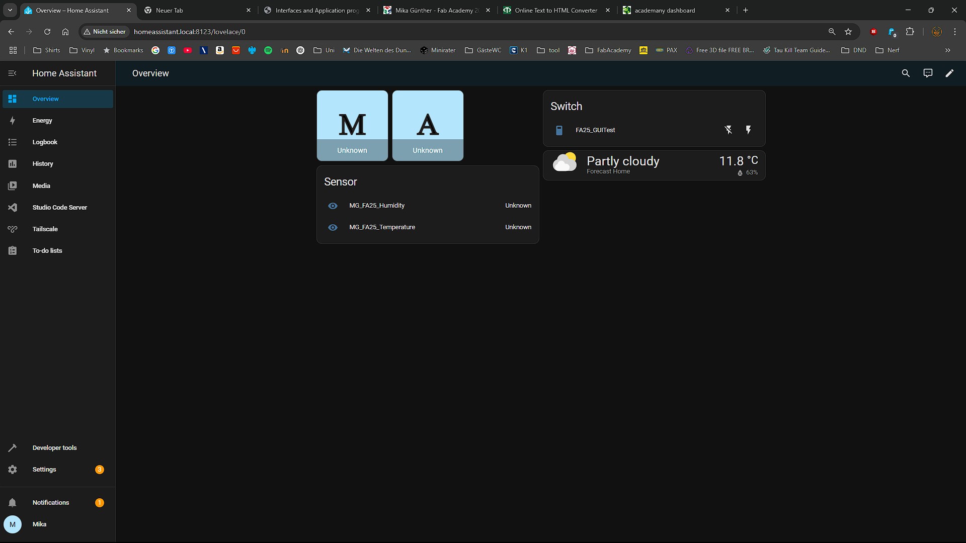
Result
In the Vido you see, how the Switch action publishes a message on the MQTT Topic, without the board, because one Video before you saw the board reacting to the Statechange in MQTT.