week 7. Computer controlled machining
This Week i made some changes on the design from Week 2
In our group assignment, we showed how our CNC Mill works and how you work safely with it. We also checked some parameters of the CNC. I worked on the Testing and Measuring after we cut the Testpieces.
The Design for the CNC
I started to design the Housing of my Final Project. It started with the upper part, where the tileplate/tileholder sits in and covers the mechanics aslwell houses the LCD. The lower part will be holding the mechanics and also electronics. The rounded Cutouts will be home of 4mm acrylic or plywood for mounting the LCD and other parts. The case is designed for 12mm multiplex.
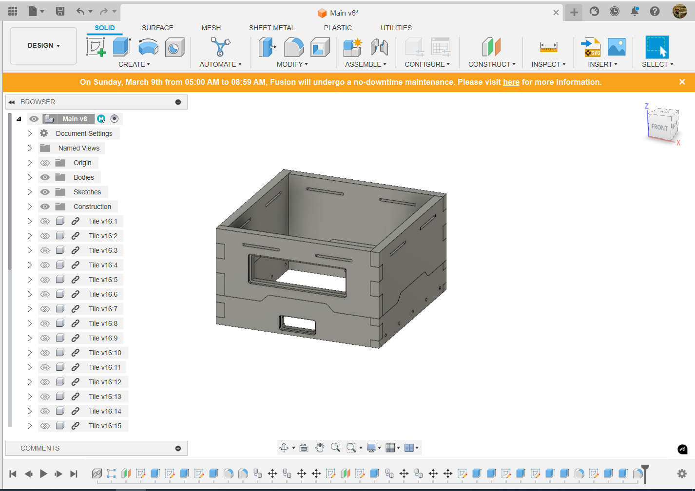
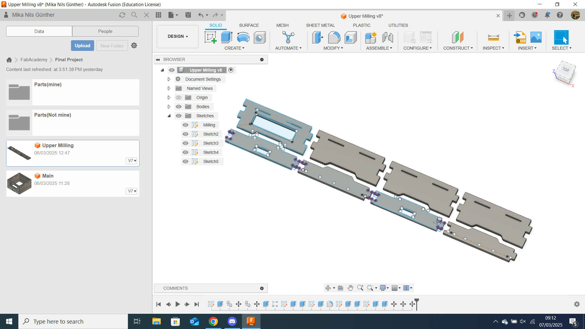
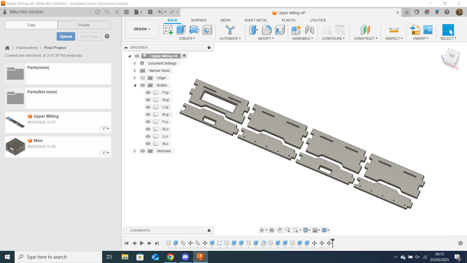
I designed it in the main file and copied the drawings to a separate file to lay it flat for milling .
Mill Setup
After changing from Design to Manifacture on the top left corner, I needed to create a setup, which contains information about the orientation of the Workpiece and Workspace as well as the size of the stock
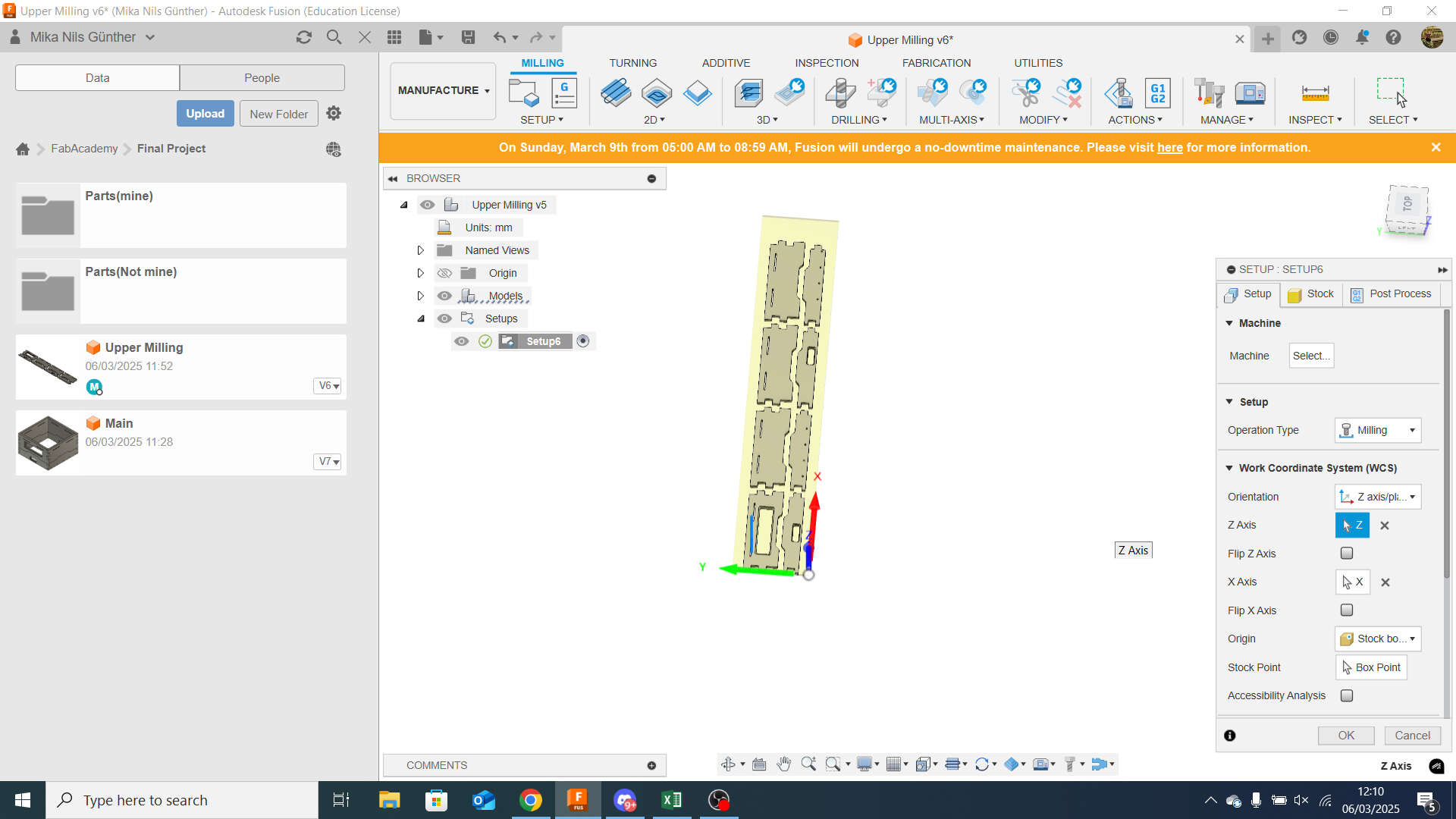
The first tab is about the process type, in our case milling and the orientation. For the orientation i use the Z- and X-axis setting. As Z-axis im using the environments z-axis and for the x-axis the environments x-axis. The Origin is "Stock Box Point" and the "origin point" is set to the top edge of the lower rigth corner. So my x-axis is at the longer side of my Workpiece/Stock
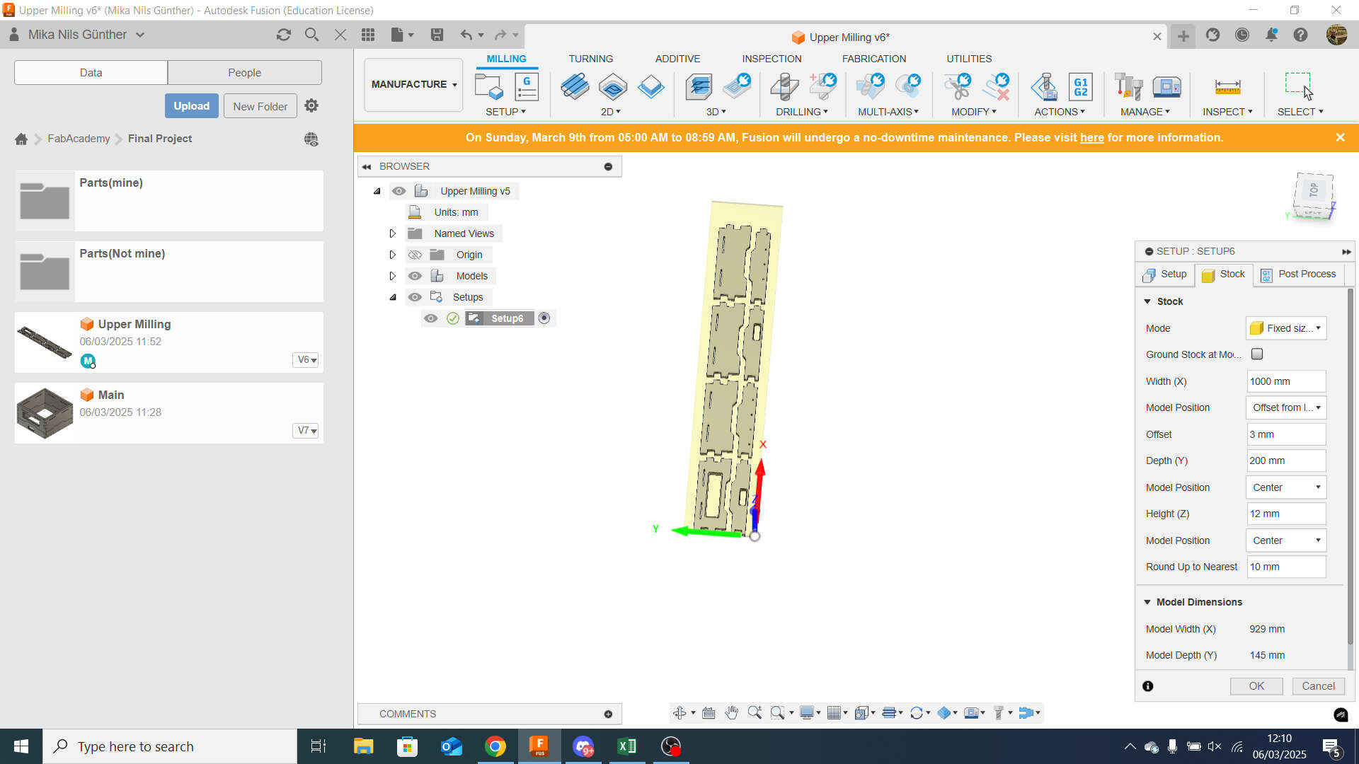
For stock i have a 12mm Multiplex sheet with 240mm width and a length of ~2500mm. I used "fixed Box size" and set the width to 1000mm because my Design is around 930mm. The depth was set to 200mm while my design has a depth of 145mm. To position the Workpiece in the stock i set the x origin to "offset from left" and use an offset of 3mm. for y positioning i selected center.
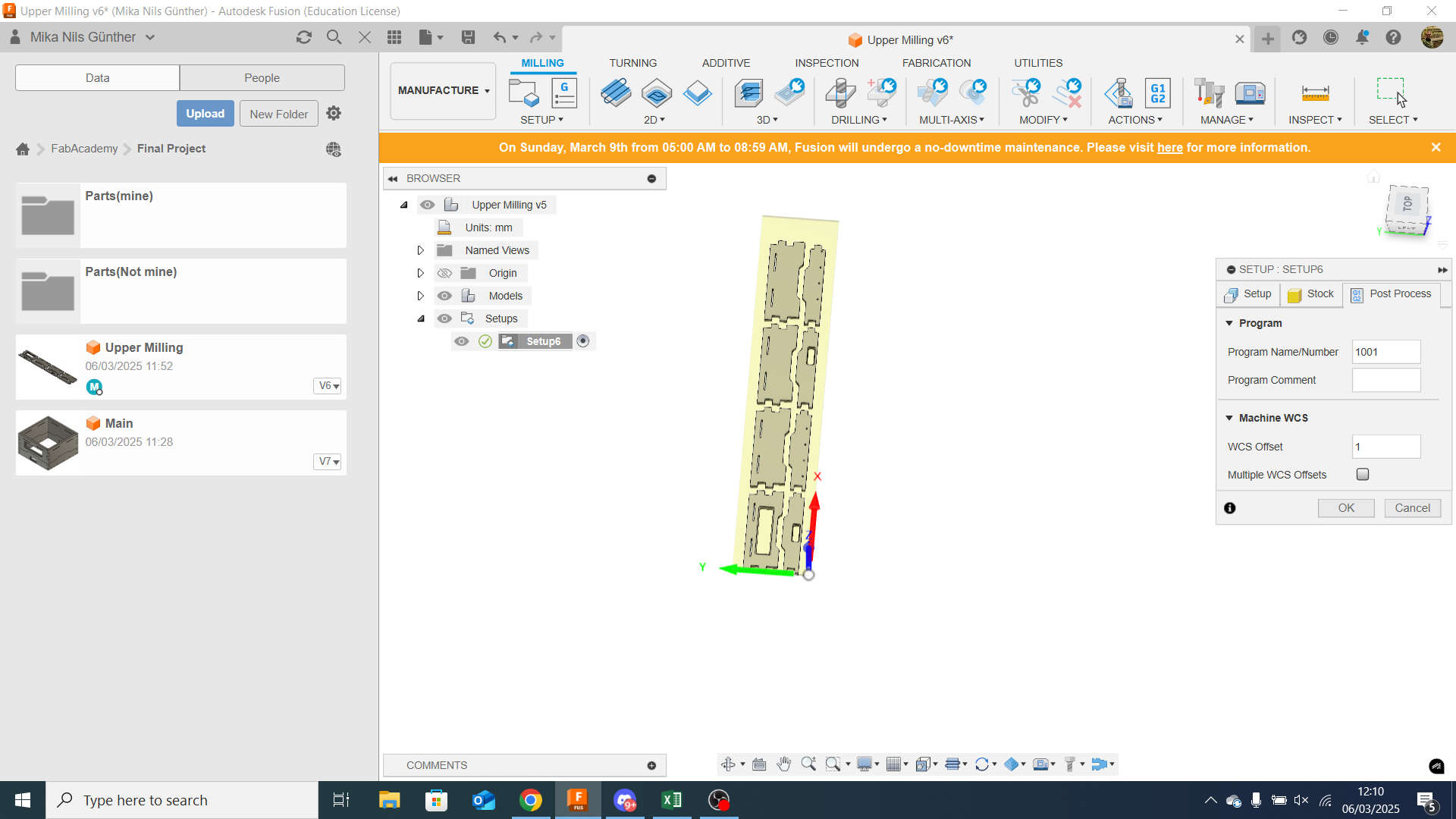
For the post process part i changed the "WCS offset" to "1".
Tool Setup
to get to the tool libray i selected "manage" -> "Tool library"
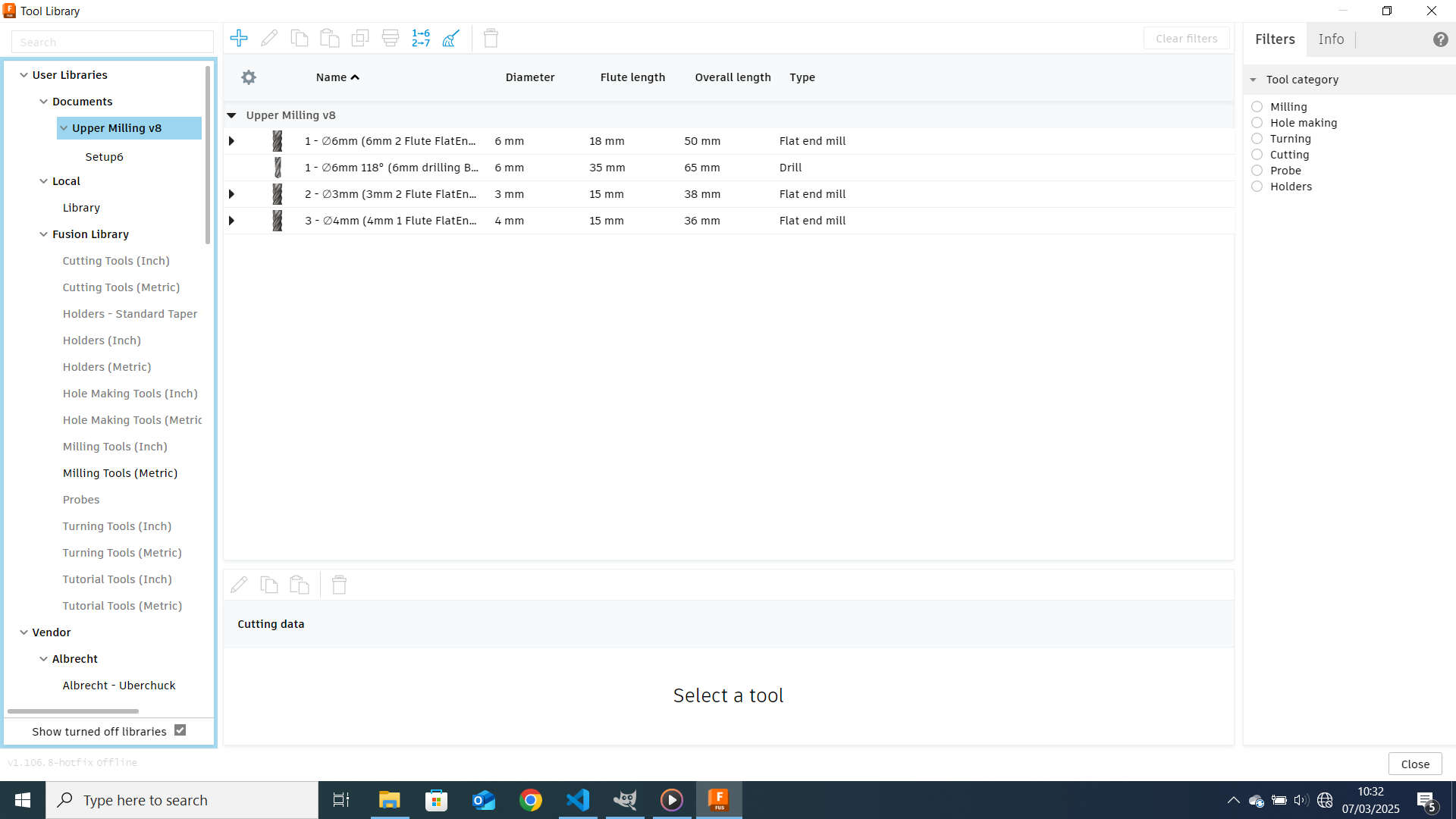
To add a Tool, I hit the plus on the rigth of the top bar.
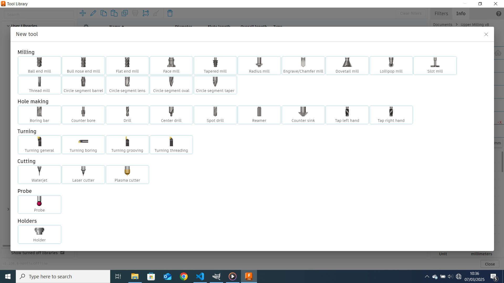
For all the used Tools i selected "Flat Endmill"
6mm
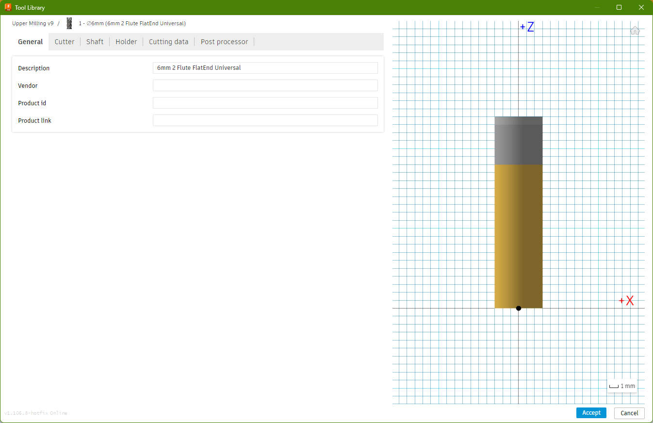
General:
description: 6mm 2Flute FlatEnd Universal
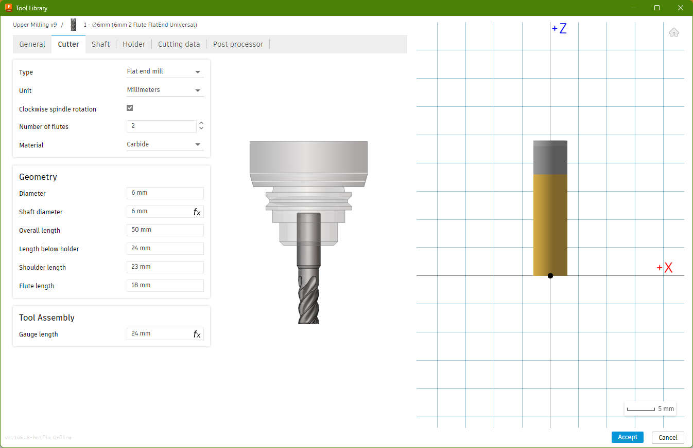
Cutter:
- Numbers of Flute : 2
- Material Carbide
- Diameter: 6mm
- overall length: 50mm
- length below holder: 24mm
- shoulder length: 23mm
- flute lenth: 18mm
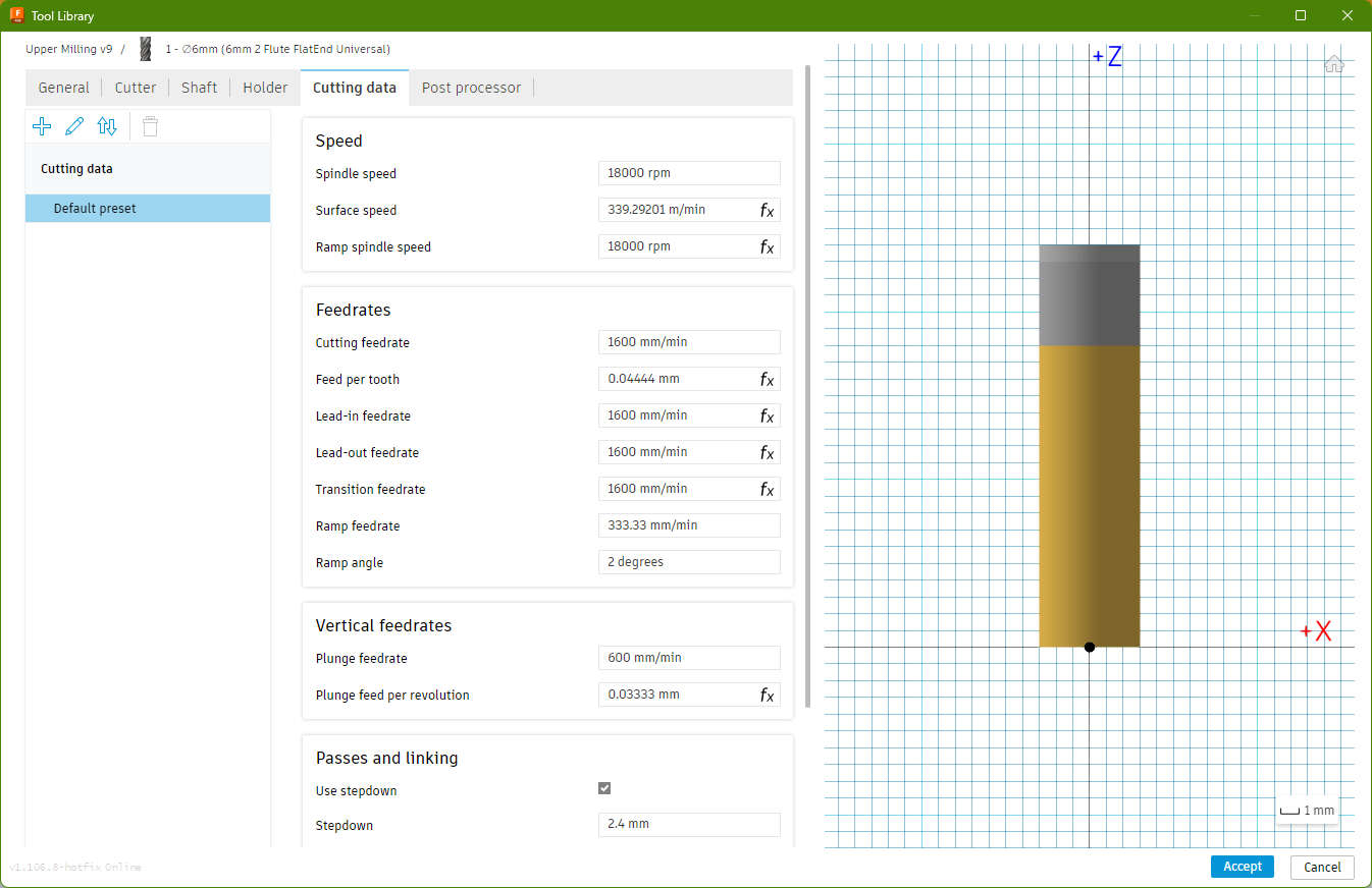
Cutting Data
- Spindle Speed: 18000rpm
- cutting feedrate: 1600mm/min
- ramp feedrate: 333mm/min
- plunge feedrate: 600mmm/min
- stepdown: 2.4mm
- stepover: 1,8mm
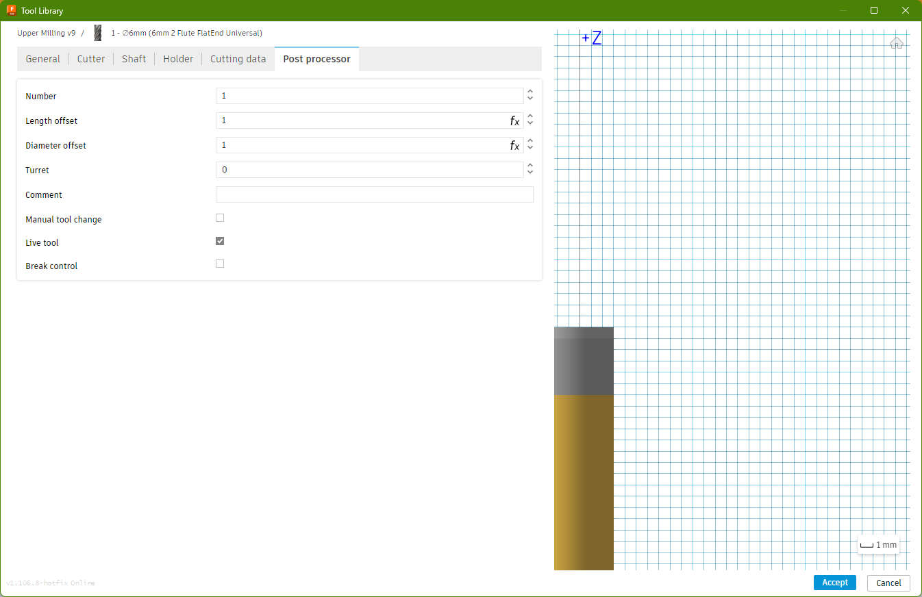
Post Processor
Number(Which refers to the Slot in the Toolchanger of the machine): 1
3mm
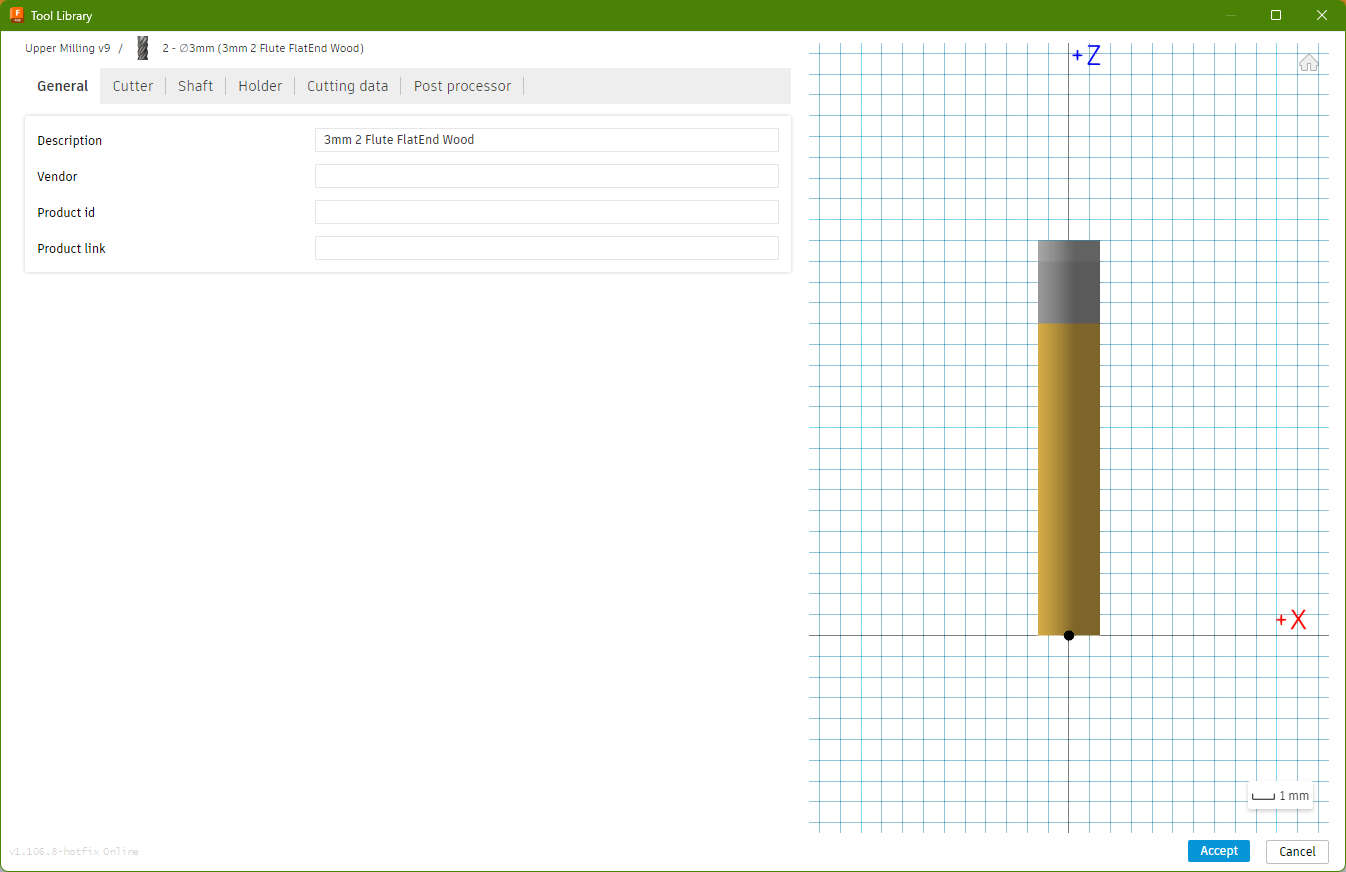
General:
description: 3mm 2Flute FlatEnd Wood
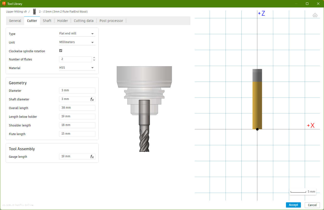
Cutter:
- Numbers of Flute : 2
- Material Carbide
- Diameter: 3mm
- overall length: 38mm
- length below holder: 19mm
- shoulder length: 18mm
- flute lenth: 15mm
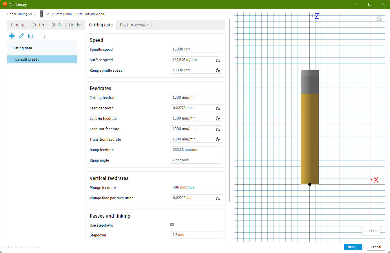
- Spindle Speed: 18000rpm
- cutting feedrate: 1000mm/min
- ramp feedrate: 333mm/min
- plunge feedrate: 400mmm/min
- stepdown: 1.2mm
- stepover: 1,8mm
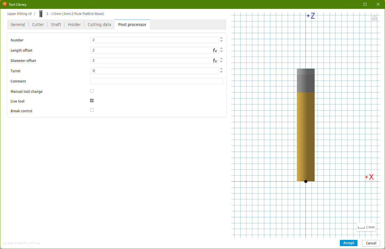
Post Processor
Number: 2
4mm
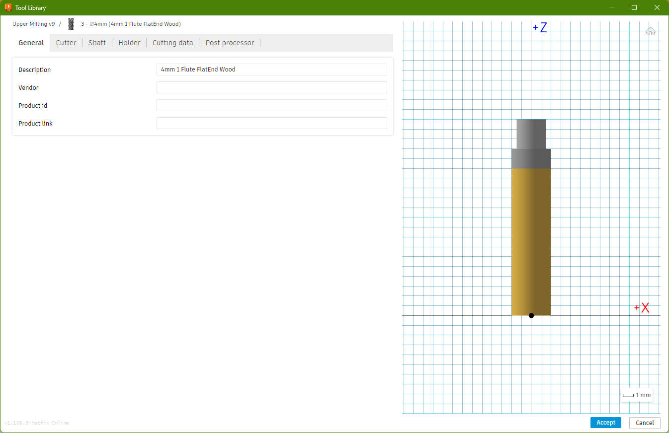
General:
description: 4mm 1Flute FlatEnd Wood
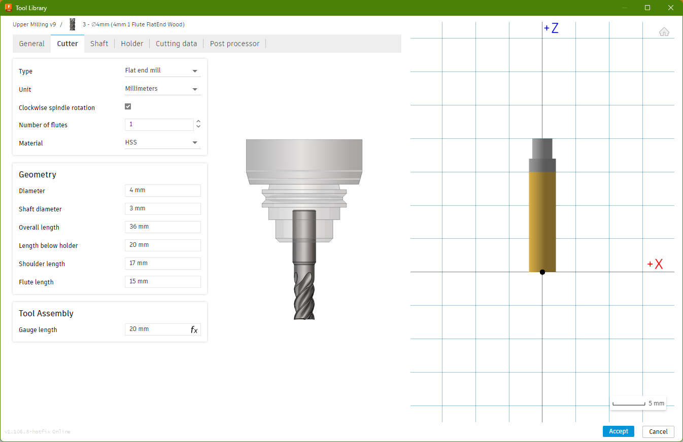
- Numbers of Flute : 1
- Material Carbide
- Diameter: 4mm
- overall length: 36mm
- length below holder: 20mm
- shoulder length: 17mm
- flute lenth: 15mm
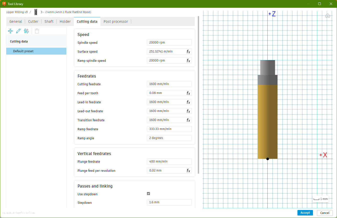
- Spindle Speed: 20000rpm
- cutting feedrate: 1600mm/min
- ramp feedrate: 333mm/min
- plunge feedrate: 400mmm/min
- stepdown: 1.6mm
- stepover: 1,8mm
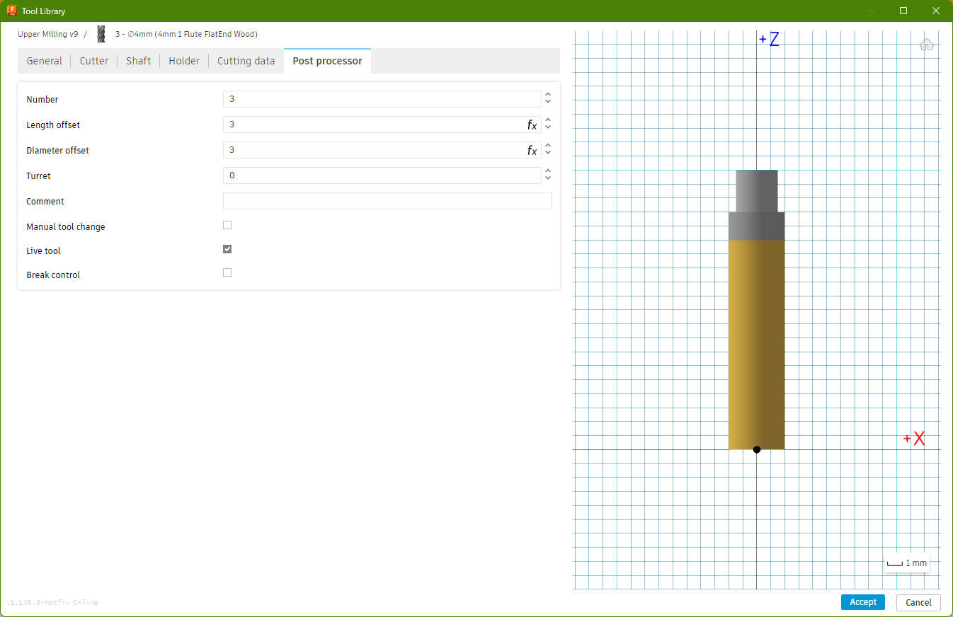
Post Processor
Number: 3
Mill Jobs
Now comes the actual Mill Jobs. I'm using Drilling, Slot and 2d Contour
3mm
I started my with Drilling holes for the edges, so that i dont need to manualy chisel or sand the inside corners. Without the holes, the inner corners would have a radius of half the toolsize
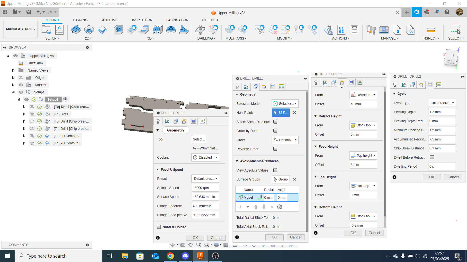
The settings for drilling are simple:
In the ToolTab i just selected my 3mm FlatEnd Mill
In the GeometryTab i selected every insice corner of the 3mm Slots(example circled red)
The HeigthsTab:
- Travel Heigth: 10mm from Retract Height
- Retract Height: 5mm from Stocktop
- Feed Heigth: 5mm from Top Height
- Top Height: Holetop
- Bottom Heigth: -0.2mm from Stock Bottom
In the CycleTab I selected chipbreaking as cycle-type with a pecking depth of 1.2mm
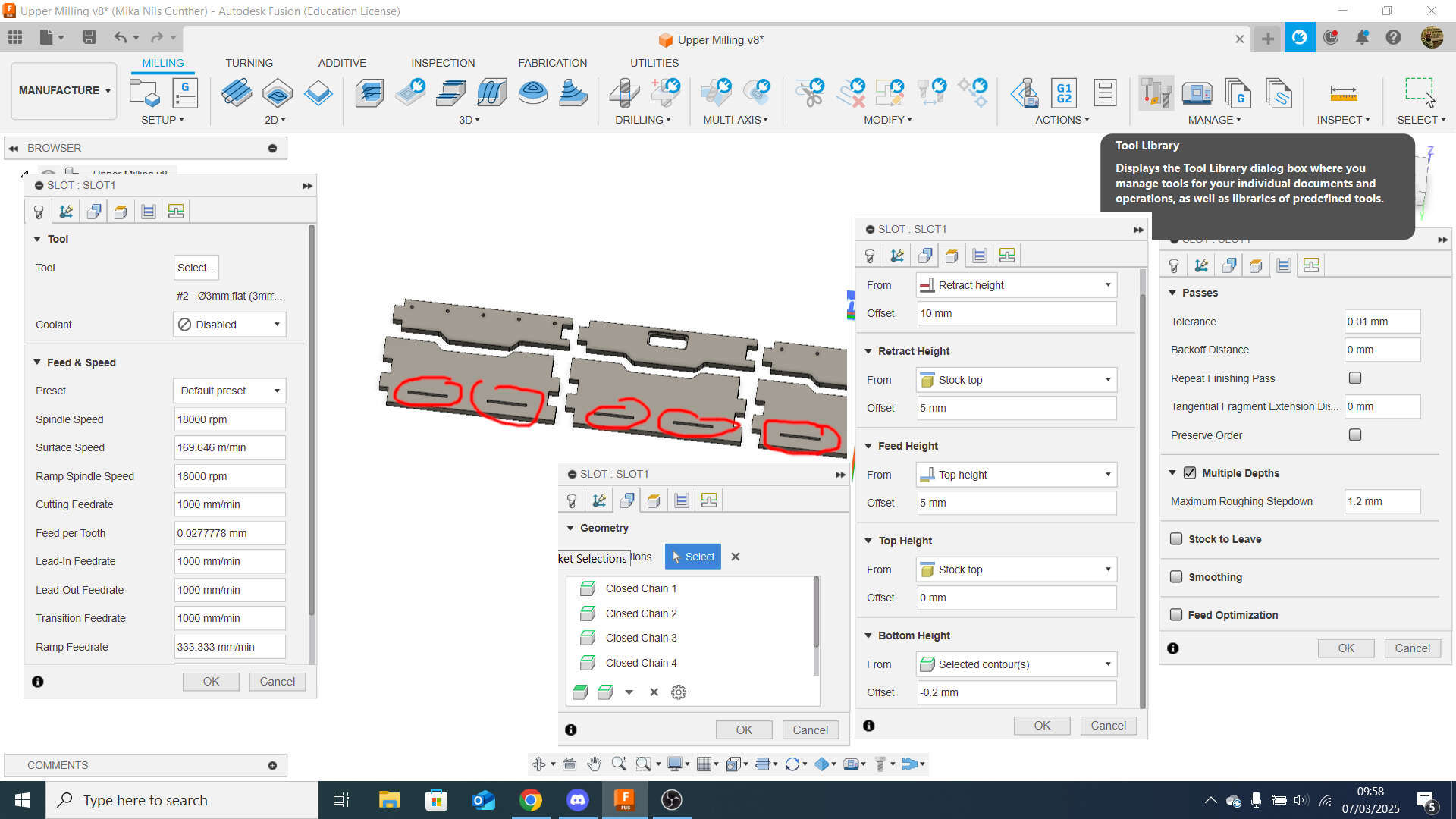
The settings for the Slots:
In the ToolTab i just selected my 3mm FlatEnd Mill
In the GeometryTab i selected every lower inside contours of the 3mm Slots(slots circled red)
The HeigthsTab:
- Travel Heigth: 10mm from Retract Height
- Retract Height: 5mm from Stocktop
- Feed Heigth: 5mm from Top Height
- Top Height: Stock Heigth
- Bottom Heigth: -0.2mm from selected Contours
In the CycleTab I used a tolerance of 0.01mm and went with multiple depth of 1.2mm each
4mm
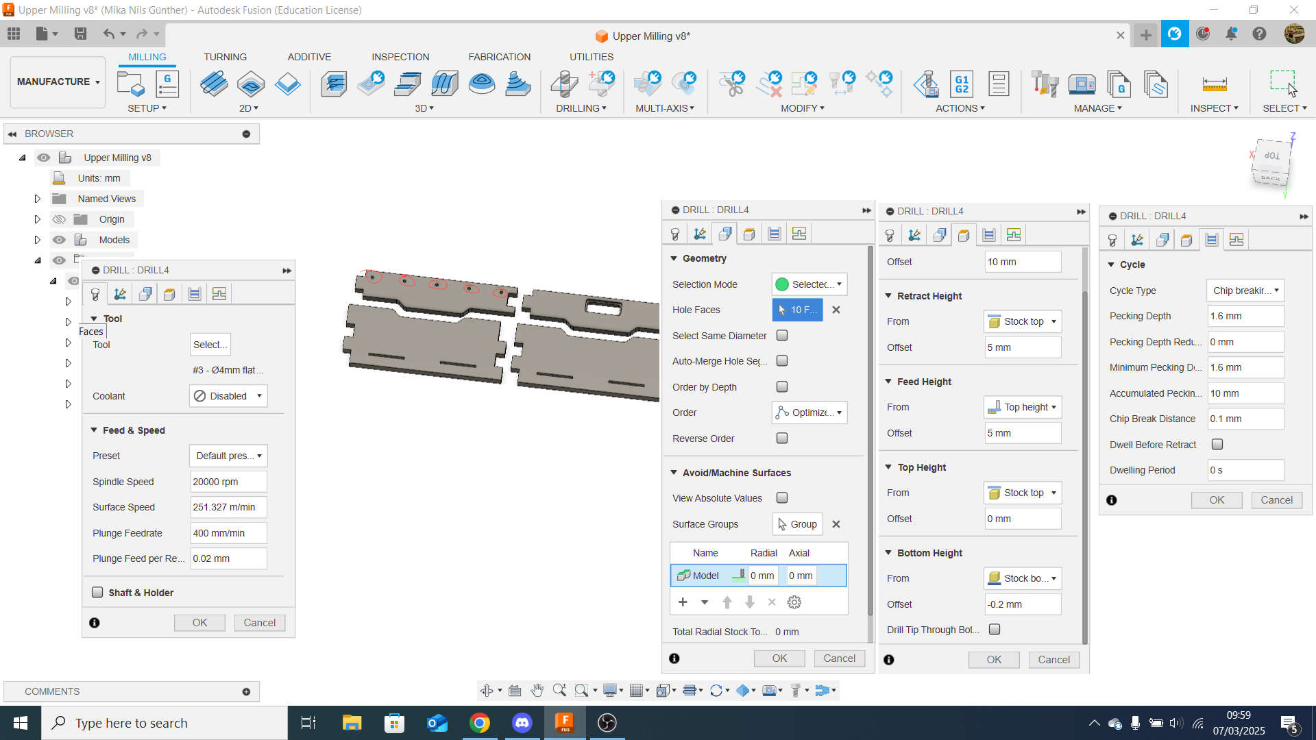
The settings for drilling:
In the ToolTab i just selected my 4mm FlatEnd Mill
In the GeometryTab i selected every of the 10 holes (example circled red)
The HeigthsTab:
- Travel Heigth: 10mm from Retract Height
- Retract Height: 5mm from Stocktop
- Feed Heigth: 5mm from Top Height
- Top Height: Holetop
- Bottom Heigth: -0.2mm from Stock Bottom
In the CycleTab I selected chipbreaking as cycle-type with a pecking depth of 1.6mm
6mm
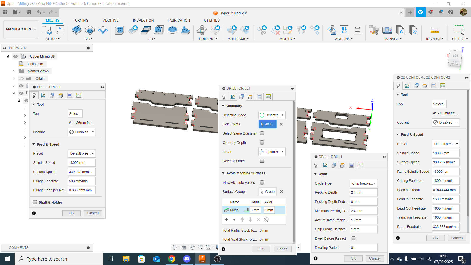
The settings for drilling:
In the ToolTab i just selected my 6mm FlatEnd Mill
In the GeometryTab i selected every inside corner of the outer Contour (example circled red)
The HeigthsTab:
- Travel Heigth: 10mm from Retract Height
- Retract Height: 5mm from Stocktop
- Feed Heigth: 5mm from Top Height
- Top Height: Holetop
- Bottom Heigth: -0.2mm from Stock Bottom
In the CycleTab I selected chipbreaking as cycle-type with a pecking depth of 2.4mm
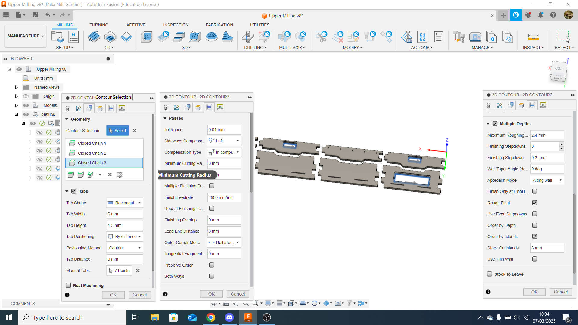
The settings for the inner 2D-Contour:
In the ToolTab i just selected my 6mm FlatEnd Mill
In the GeometryTab i selected every lower inside contours of the Workpieces (slots circled red). You need to keep in mind i have two different inner contours. First the higher one wich is for the 4mm Lip and second for the complete cutout of the inner contours.
The HeigthsTab:
- Travel Heigth: 10mm from Retract Height
- Retract Height: 5mm from Stocktop
- Feed Heigth: 5mm from Top Height
- Top Height: Stock Heigth
- Bottom Heigth: -0.2mm from selected Contours
In the CycleTab I used a tolerance of 0.01mm and went with multiple depth of 2.4mm each
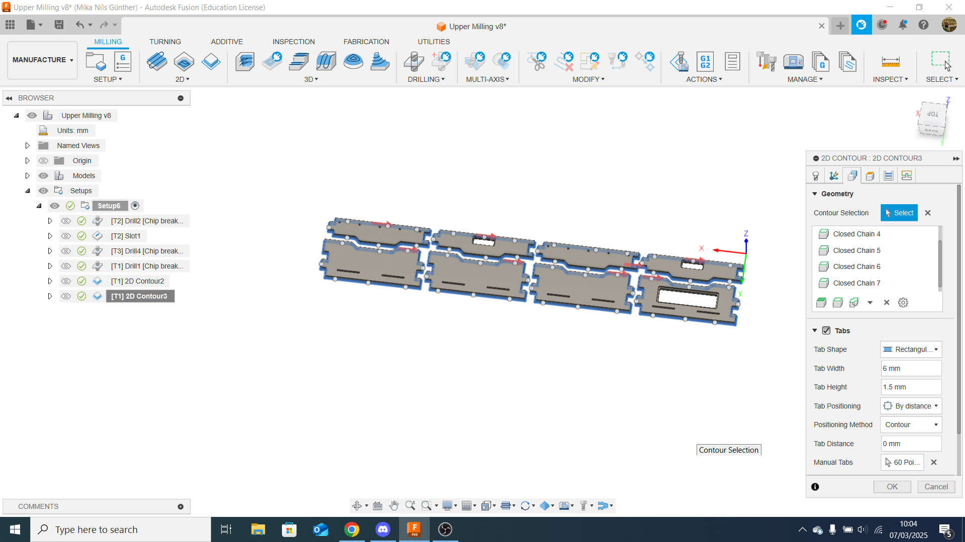
The settings for the outer 2D-Contour:
In the ToolTab i just selected my 6mm FlatEnd Mill
In the GeometryTab i selected every lower outside contours of the 3mm Slots(slots circled red)
The HeigthsTab:
- Travel Heigth: 10mm from Retract Height
- Retract Height: 5mm from Stocktop
- Feed Heigth: 5mm from Top Height
- Top Height: Stock Heigth
- Bottom Heigth: -0.2mm from selected Contours
In the CycleTab I used a tolerance of 0.01mm and went with multiple depth of 2.4mm each
Simulation
To simulate, i right-clicked on the setup and selected simulate
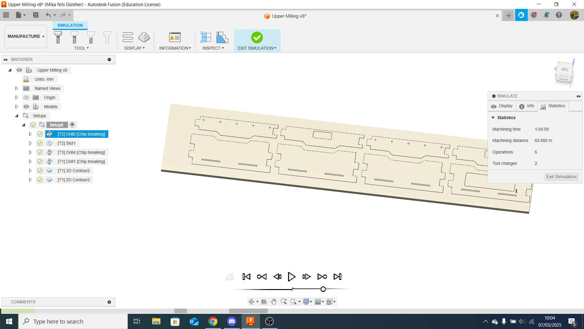
The Mill Job will take 1h 5min acording to the Simulation and it will have 2 Toolchanges
CNC File
Similar to the simulation i right-clicked on the setup and selected Post Process. This automaticaly created an nc-programm:
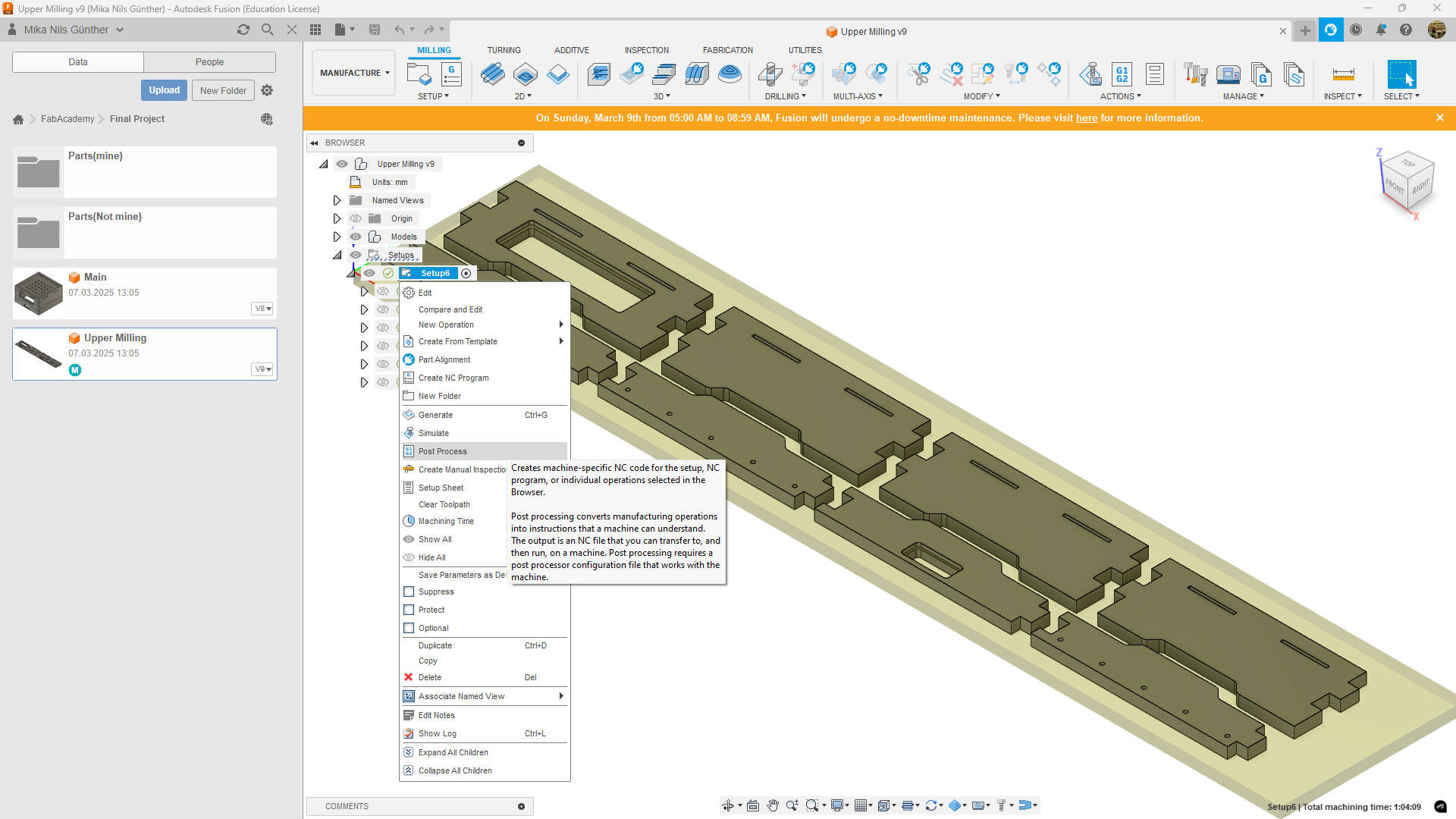
Now i needed to change the Settings for NC-Programm
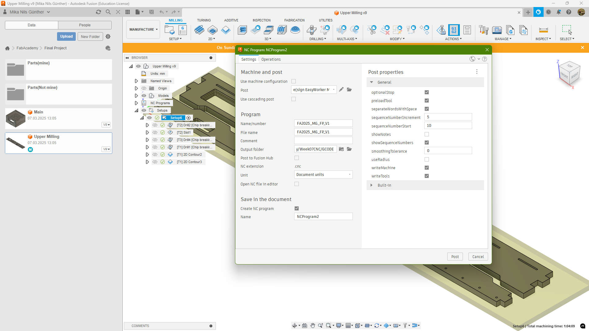
- Post: Postprocessor of our Machine found on our Labs Wiki.
- Name: Some rememberable Name
- Folder: Where i saved it
Milling
In our group assignment,we showed how to mill with our CNC. I did it like there. The only difference was, that i used the mill bits also for Drilling, so that i dont need to manually change anythingwhile the mill operation.
Rough Cut
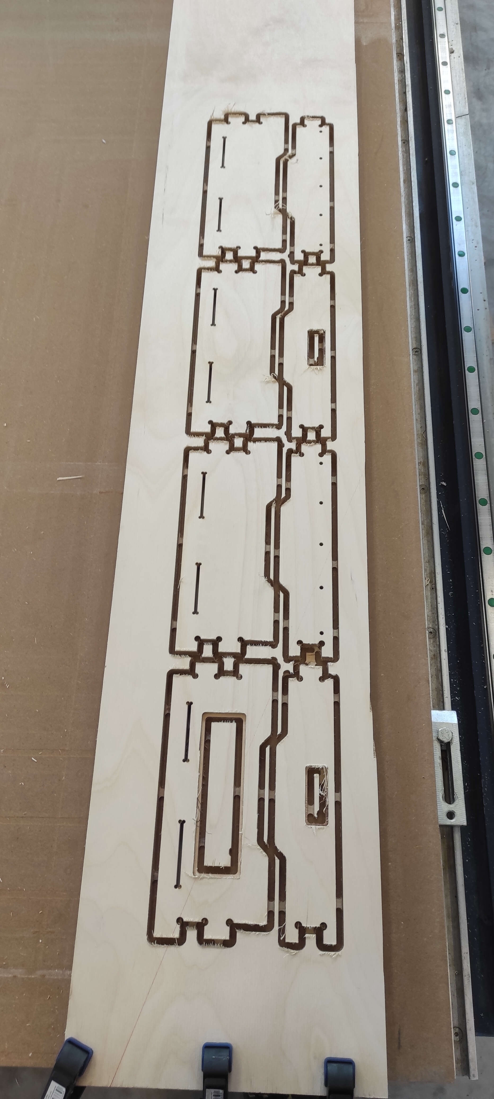
As you can see the cut is quiet rough and and the pieces are still atached through the tabs to the Stock.
Cleanup
I first removed the single pieces from the Stock
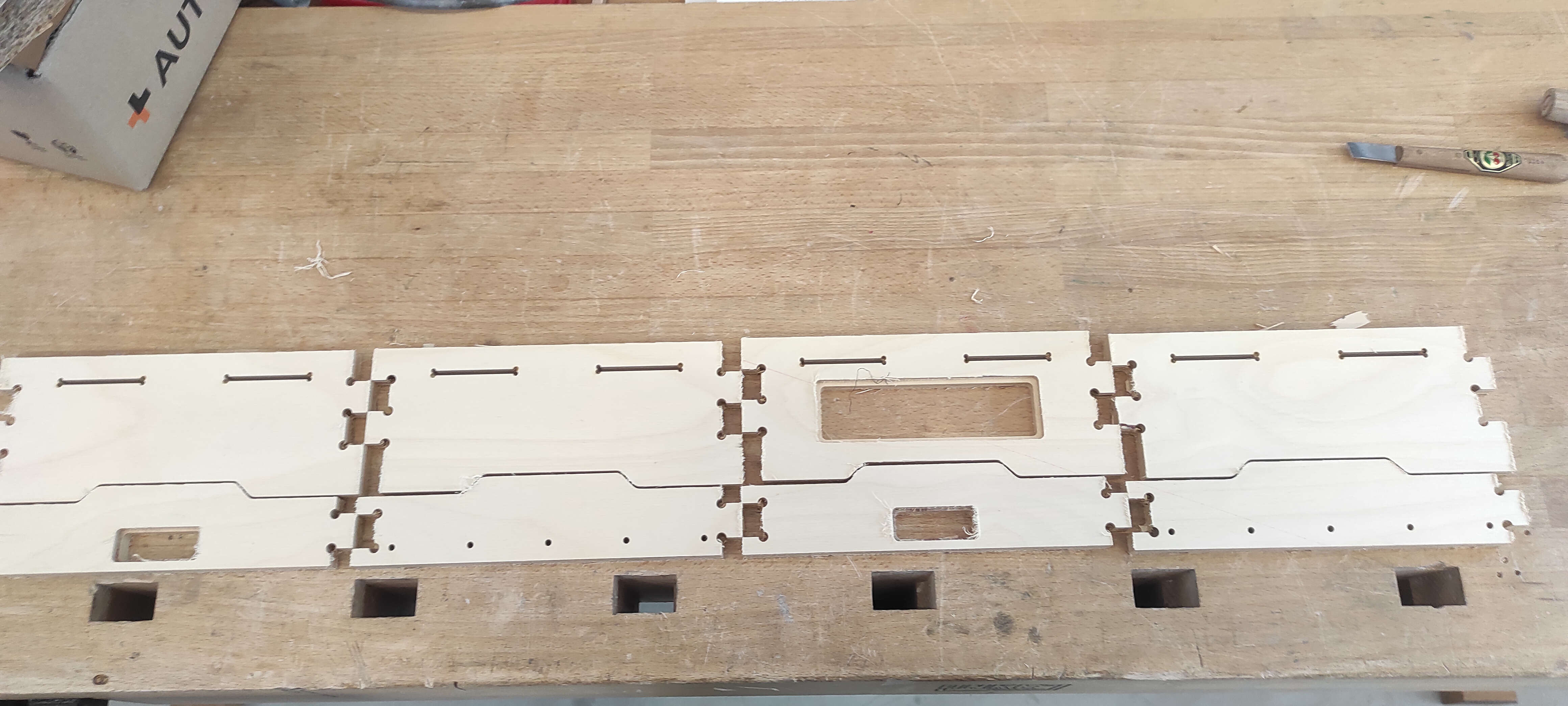
Then I cleaned everything with the chisel and some Sandpaper
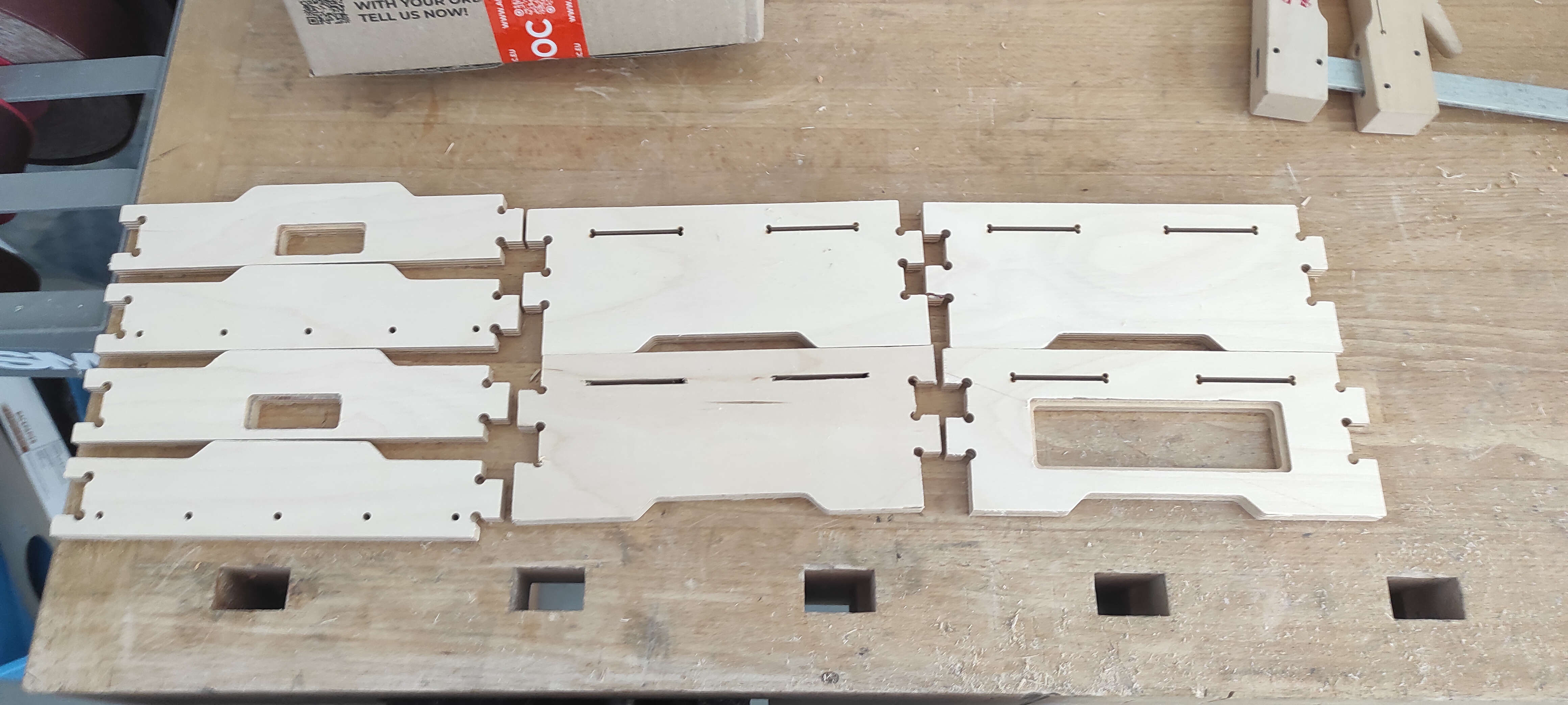
Assembly
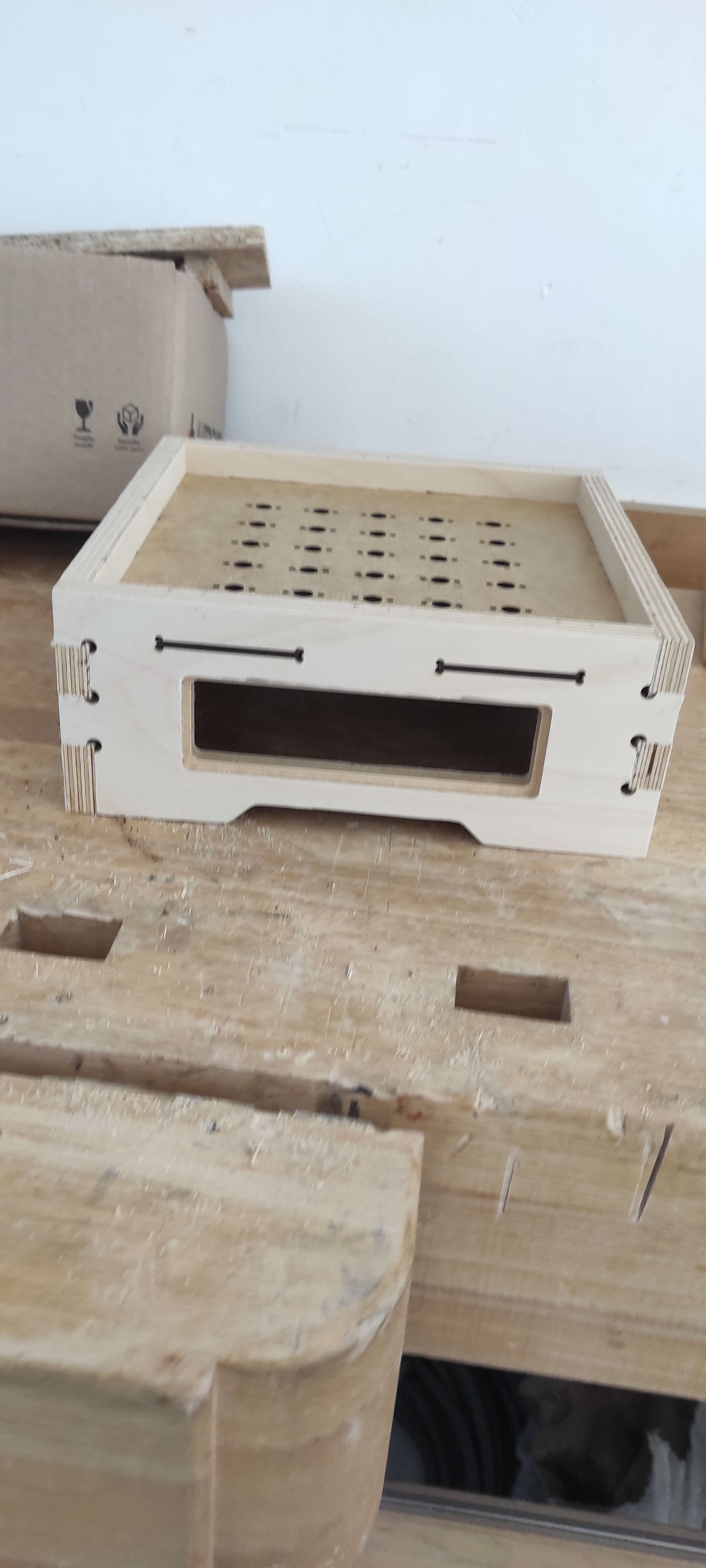
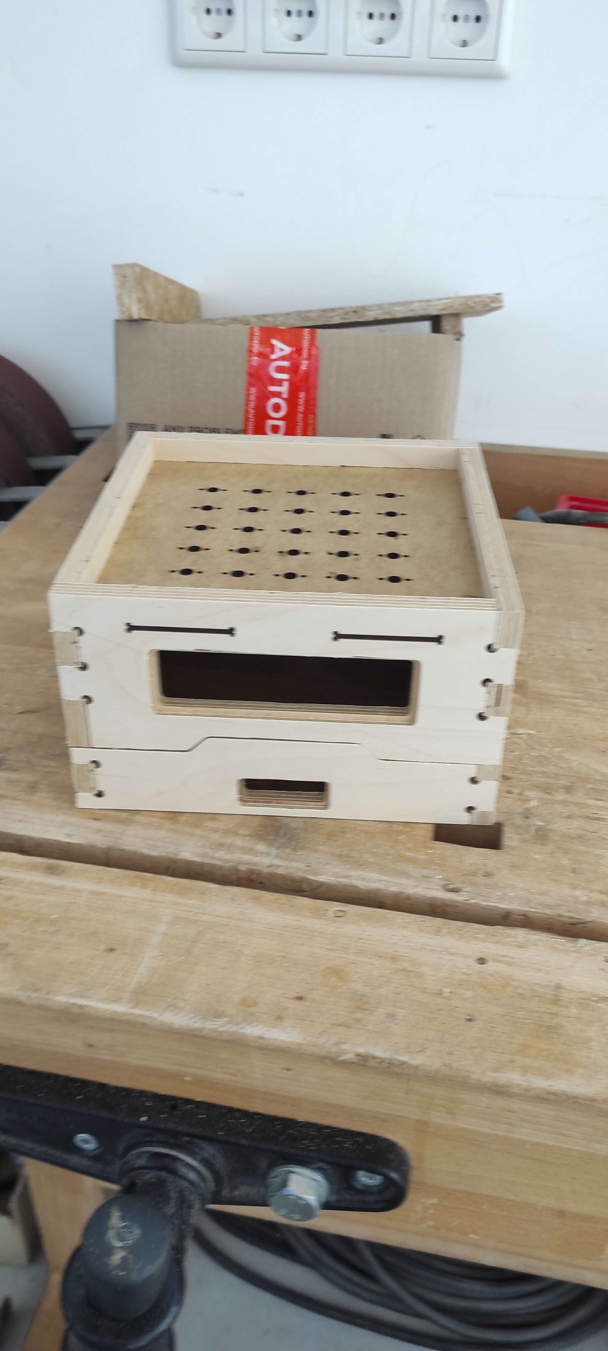
I assembled everything with a mallet. I used the same tolerances as in our Group assignment so i dont need any glue or fastener. I also added a lasercut piece. This was cut like in Week 3. This lasercut piece is used to attach the Tileholders to.
Top:
Top + Bottom:
Download
MillFileslasercut
the lasercut piece you saw, was made like in week 3. Computer controlled cutting
DXF of the Tileplate with 0.15mm kerf