ABOUT OUR MACHINE

The big CNC in our lab is the "eLsign EasyWorker MasterPro 2513". We have also a Entry to the Machine on our FabLabs Wiki, where you can find for example the Post-Processor
- The machine's workspace measures 2500 x 1300 x 200 mm.
- With a maximum speed of 19,000 mm/min, the equipment ensures quick processing and transportation.
- For high precision, linear guidance is used.
- The equipment is compatible with G-Code and HPGL data formats.
- The power supply specifications are flexible, supporting either a single phase or three phases at a voltage of 230V or 400V.
- Extension with an pivoting arm to the dust-collecting System.
- Automatic toolchanger
The technical data for the CNC is as follows:
Additional modifications:
Testing The Alignment, Runout, Fixturing, Speeds, Feeds, and Materials.
The test components include a plate designed to test carving a rectangular hole in the middle to conduct fitting tests with various types of dog bones that are made within the manufacturing workspace. To assess the fitting, a matching piece is desgined to insert into the rectangle hole This piece additionally, includes a circular pocket in the middle to test whether this can be pushed out manually after milling.
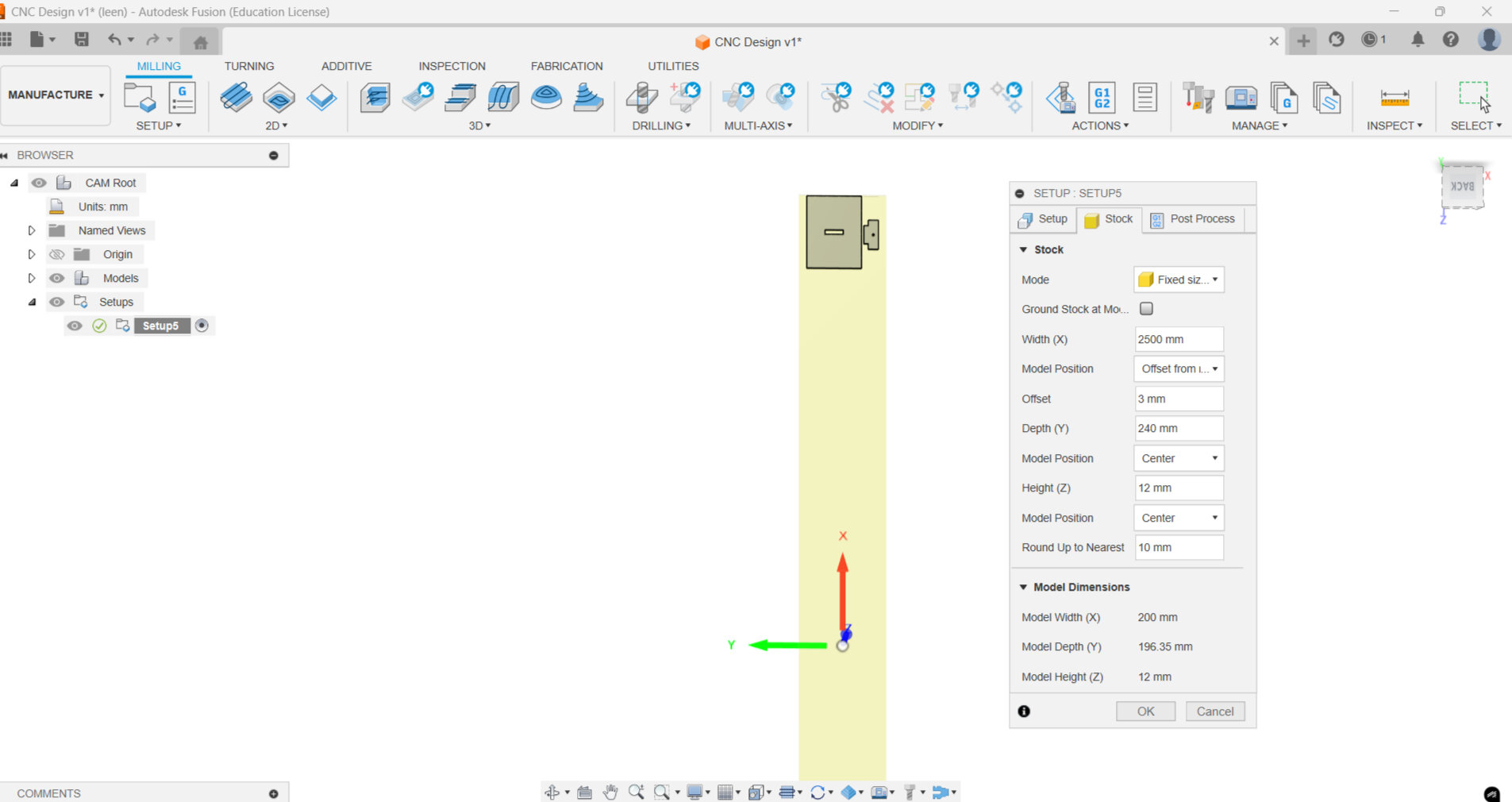
In the manufacturing workspace, a new setup is created. Here it is important to make sure that the z-axis is pointing upwards and the origin is at the bottom of the edges of the stock to obtain the best outcome.
In the stock section, change the mode to absolute size box and set the correct measurements. Height should equal the material thickness. After that, you can click on "OK".
To set pocket parameters, navigate to 2D menu and select 2D pocket. Now we can enter the specifications of the tool we will use by selecting a tool: click on + to enter a new tool.
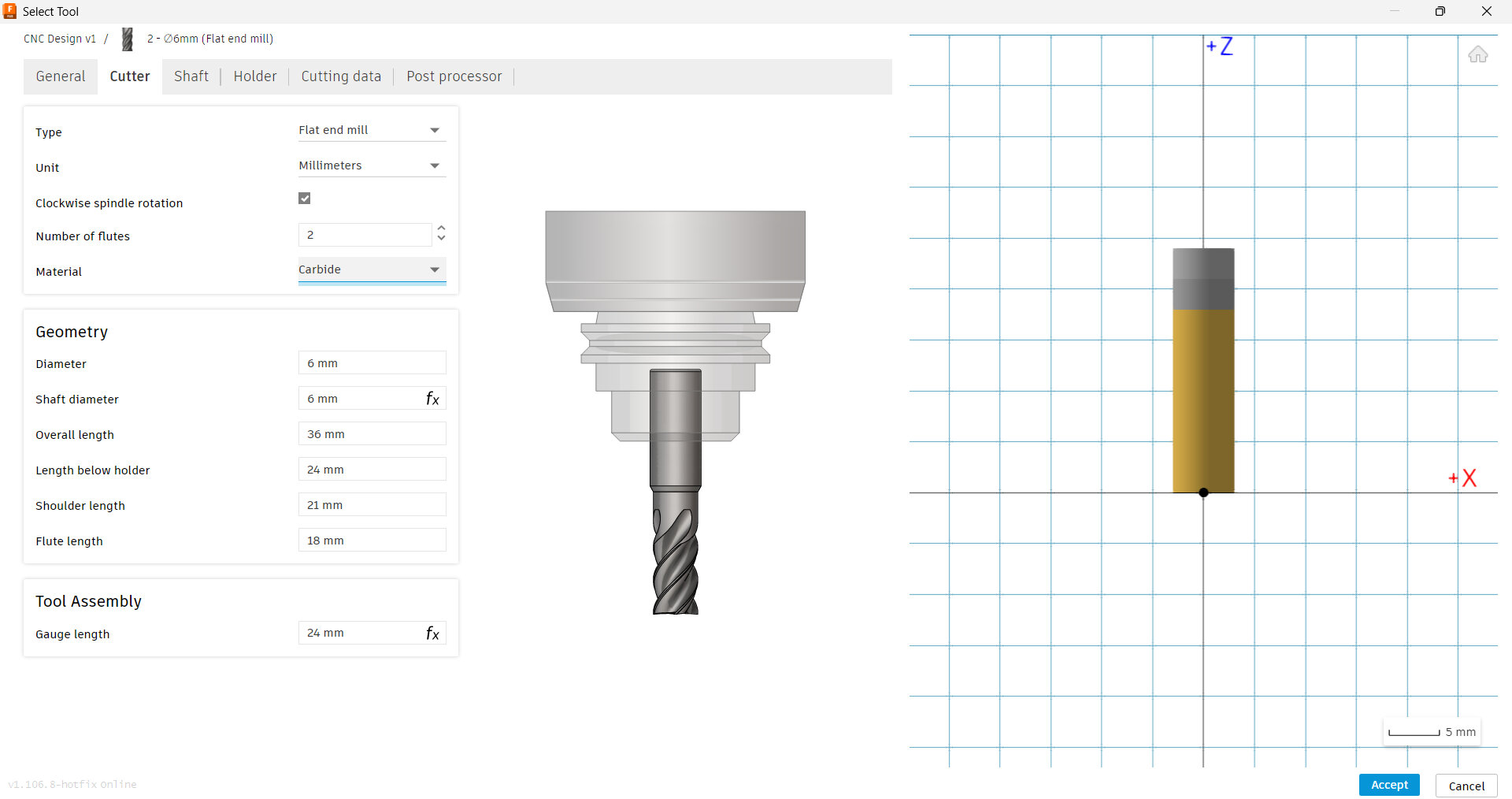
From the tool profile, select flat end mill 6mm then as shown in the pictures we modified the cutter and the cutting speed parameters.
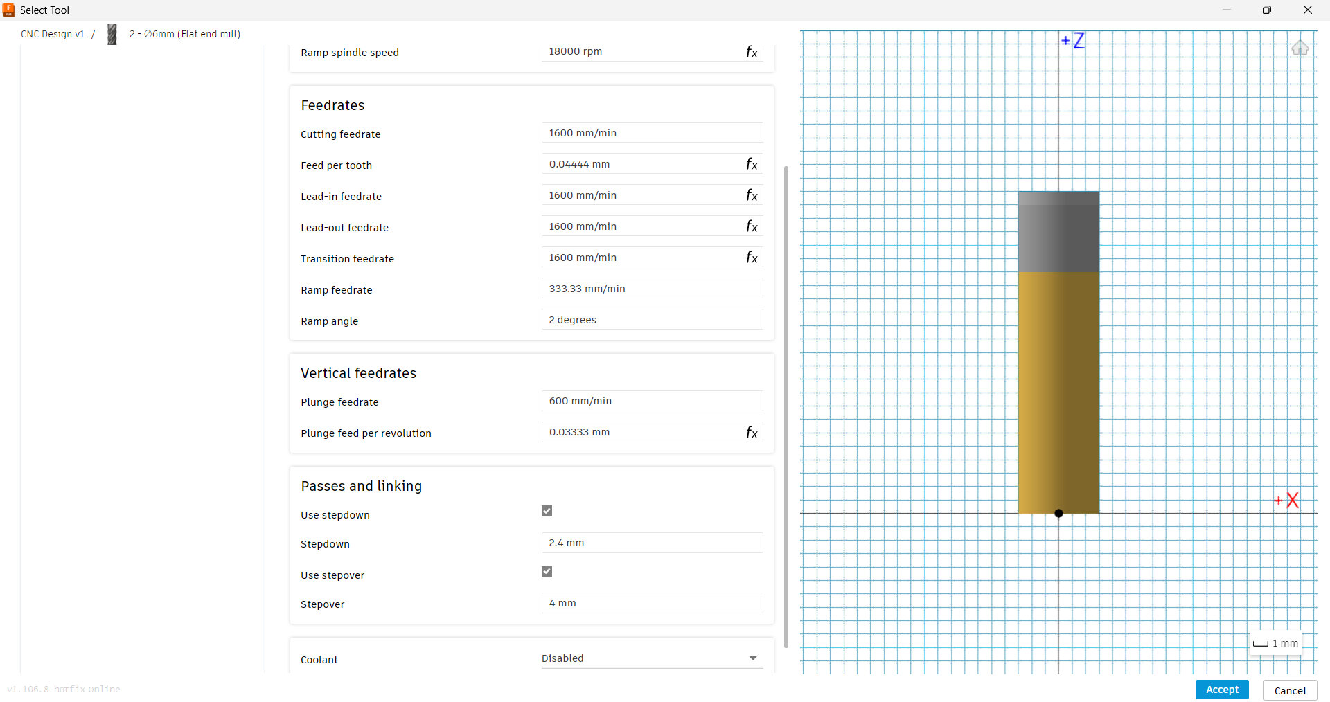
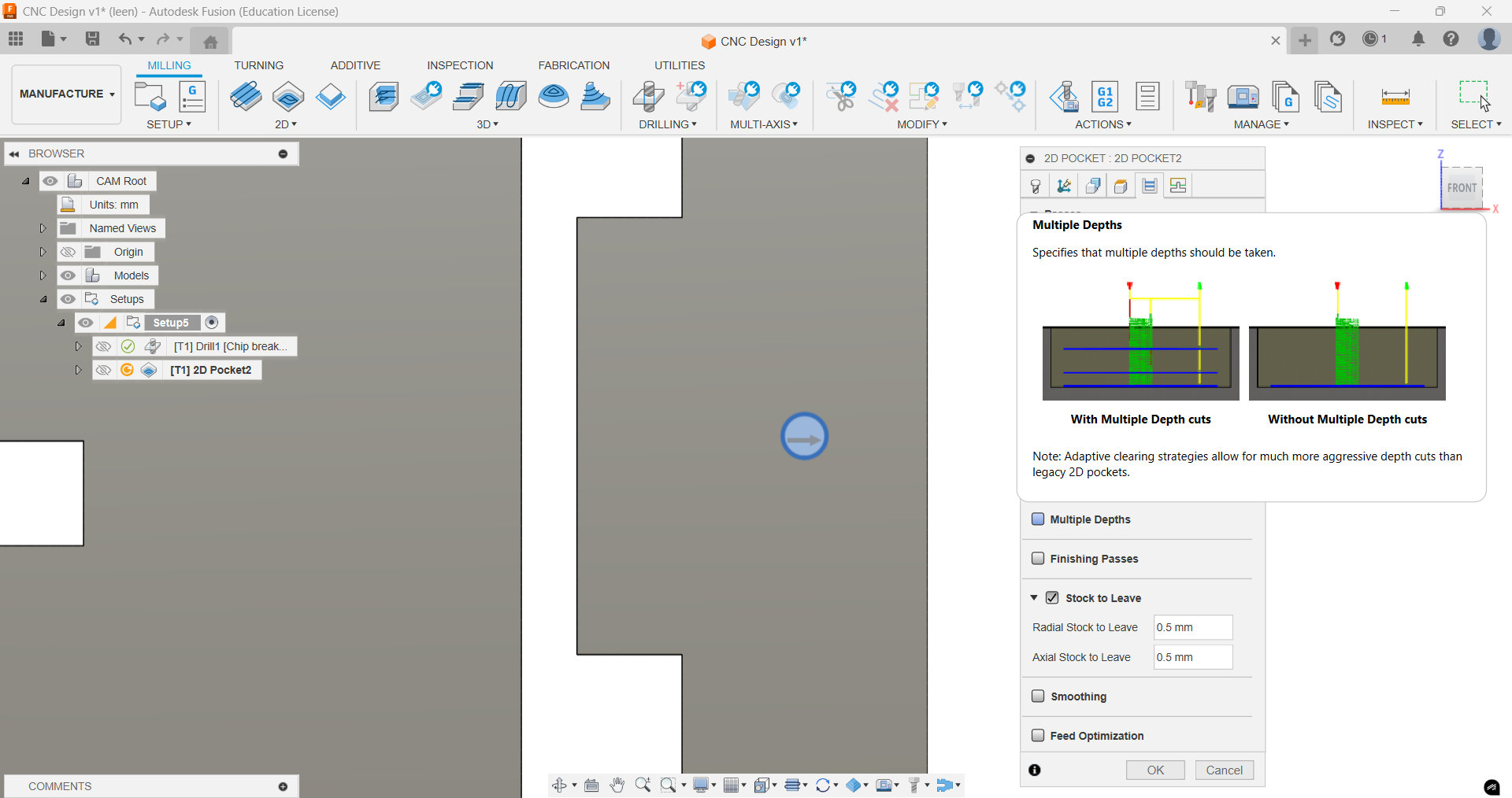
Now go to the Passes tab and adjust the tolerance to 0.001. Enable 'Multiple Depths' and customize the parameters accordingly. After selecting the right parameters for the cut, you click on "OK".
Now we need to set the drilling tool parameters, go to Drilling menu > Drill, and enter a new tool by clicking plus. Again from the tool profile, select 10mm 118° Drill. Then as shown in the pictures we modified the cutter and the cutting speed parameters. Make sure that in Post Processor tab you set the number to 1. That is the convention in our lab.
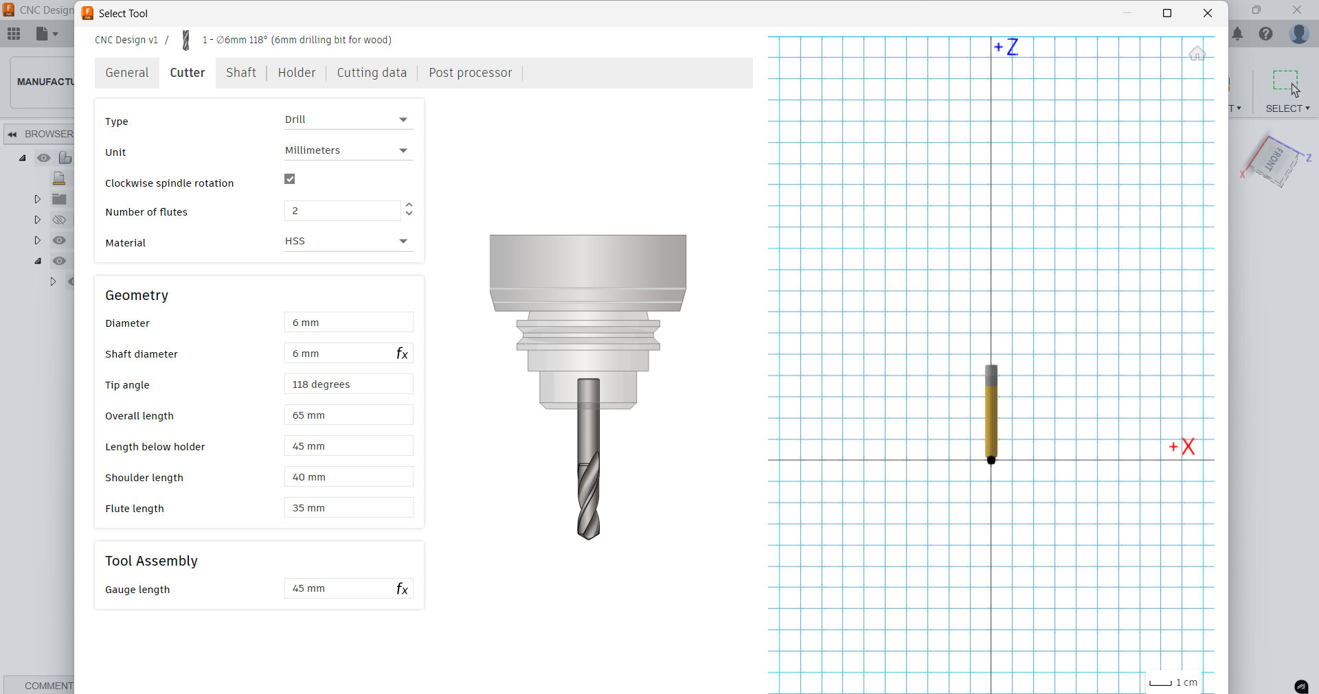
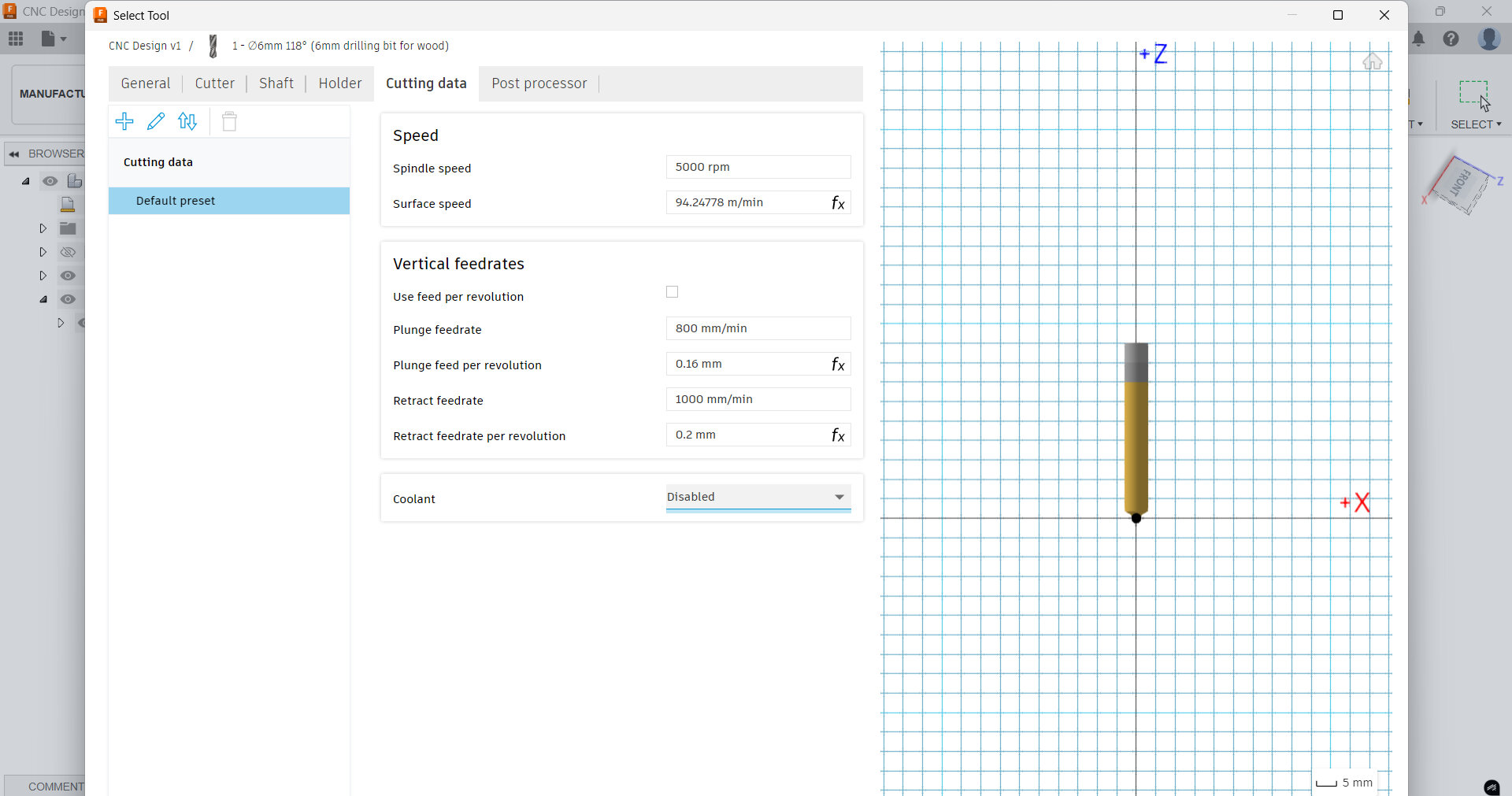
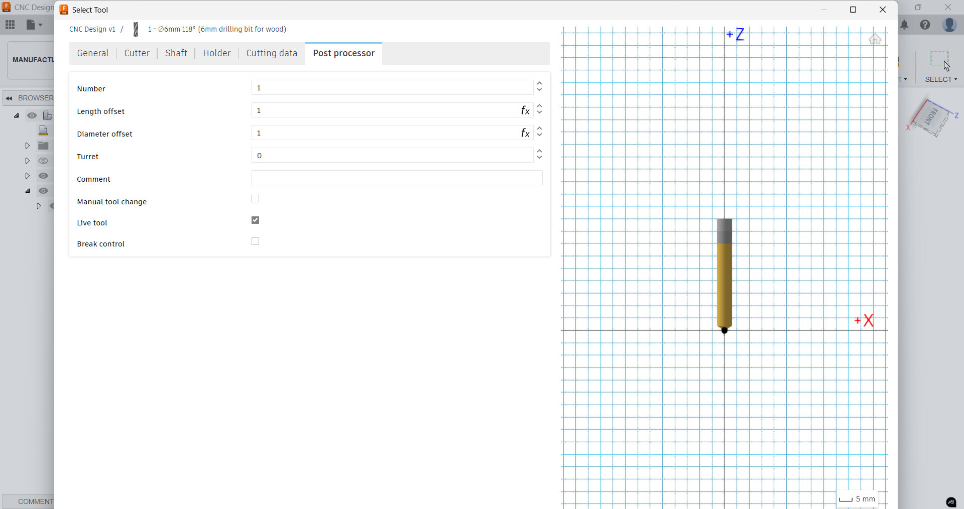
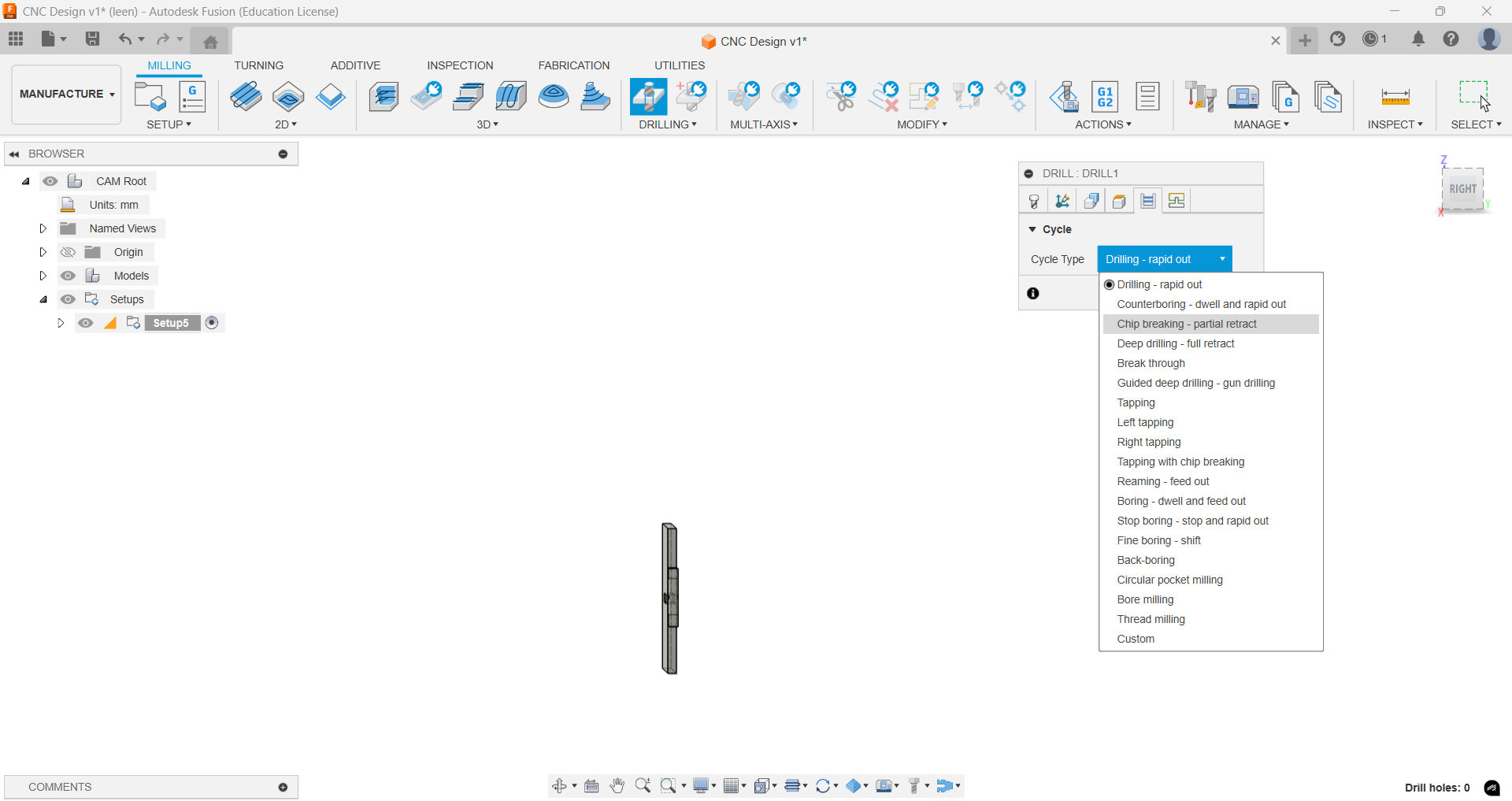
After this is done, go to geometry tab and play manually the hole points to create the the dog bone joint. In the Heights tab, set the top height to stock top and bottom height to bottom stock. For the Cycle, select chip breaking – partial retract.
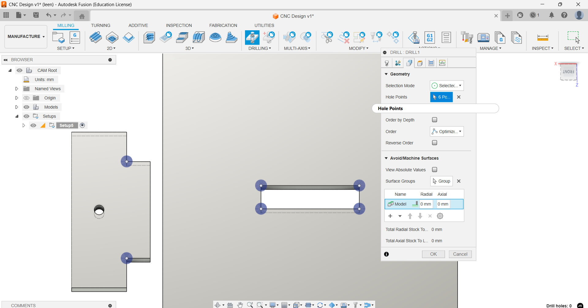
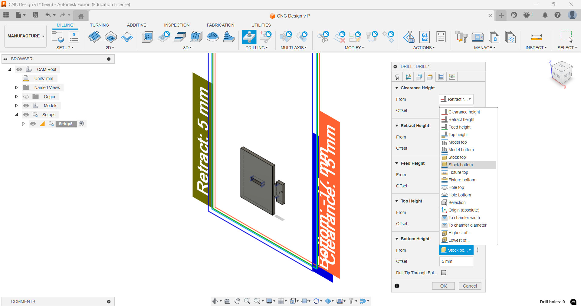
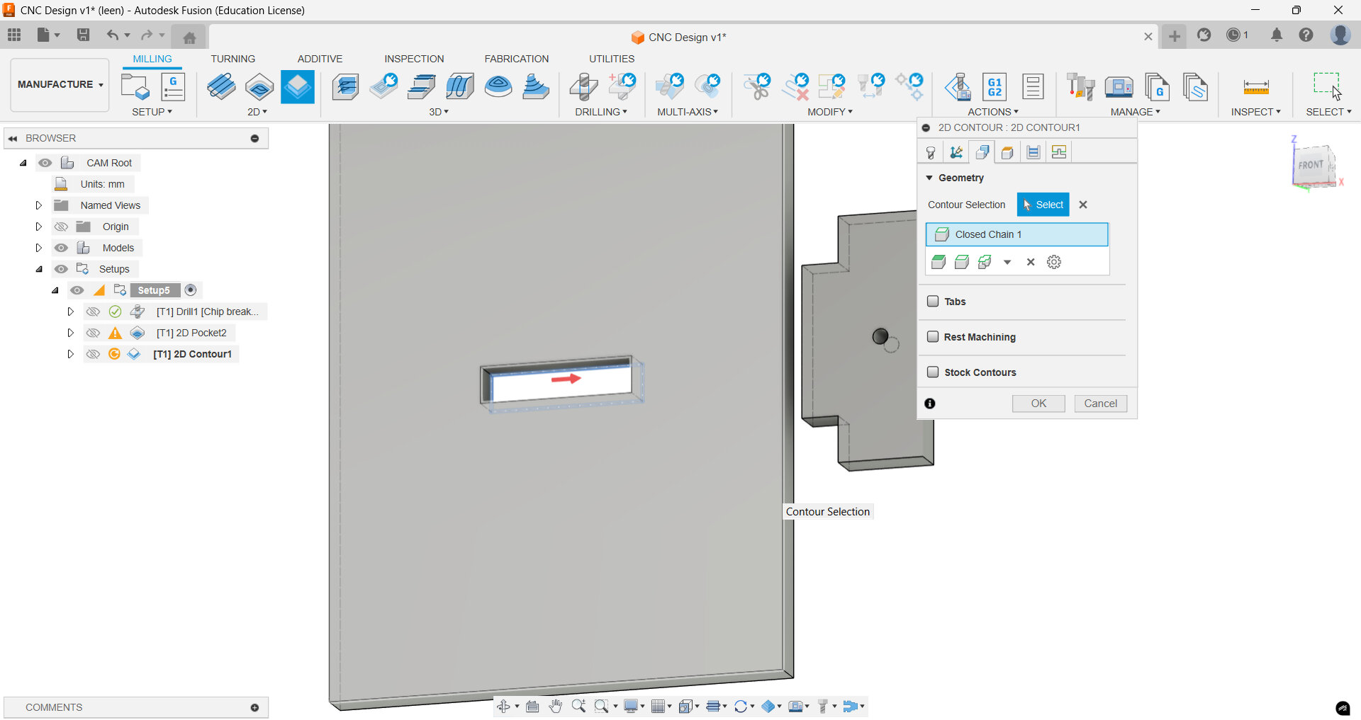
Now we go again to 2D menu and select 2D contouring for the outer frame. In the Geometry, select the bottom edges of the inner rectangle. In the heights menu, make sure you offset the bottom height slightly.
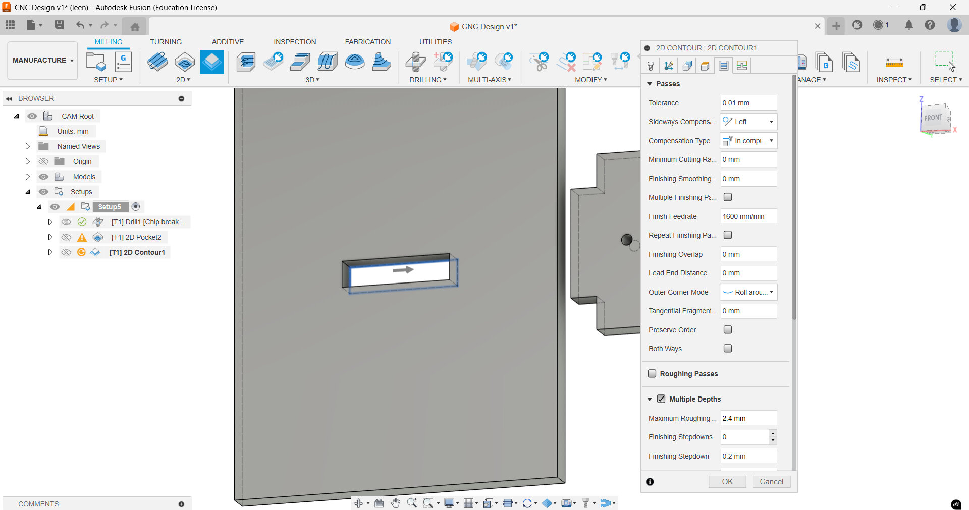
Again in the passes menu, make sure you check multiple layers>/strong and set the maximum roughing to 2.4 mm, because it does not take the parameters set already when we entered our tools specifications.
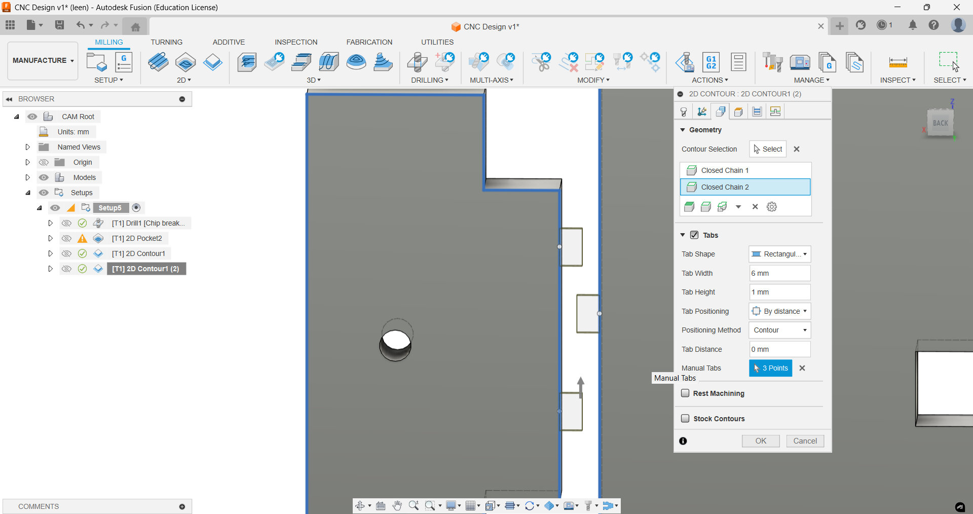
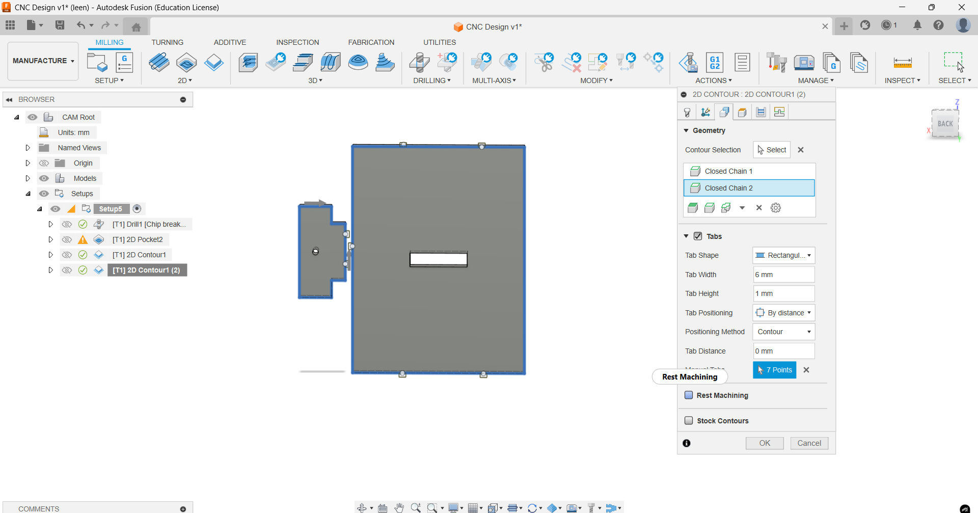
Finally, right click on the 2D Contour setup and click Duplicate. This time in the Geometry select the contours to be the bottom outer frames of both pieces (the big rectangle and our fitting piece). In the same menu, check tabs to secure the workpiece and select 3 points on the smaller pieces and 4 additional points on the bigger piece. These tabs can be post processed and filed after milling.
Create the post-processing file when you've confirmed the simulation produces the desired result. This is done via Post Processing by right-clicking on the "Setup" button on the right side of the window. The "folder" icon next to "post" should be clicked. Select "Local" in the new window, then click Import at the top. Click "Select" after selecting the necessary file (based on the machine). Now, to create the post precessing file (G code), navigate to the output 'folder' icon, select the location you want, and then click 'Post'.
Now we are ready to mill!!
Machine Safety
Although the CNC machine is a strong tool, improper use can make it hazardous. To keep you and other people safe when using the machine, it is crucial to abide by the safety instructions. It is very important to avoid operating the CNC if you are alone in the lab. Additionally, you must use earprotection and safety-glasses to protect our ears and eyes from any unforeseen incidents.
It is important to remember that a machine, no matter how smart it may seem, is only as smart as the user. This means any mistakes in operating the machine are human errors. Here’s how to get started with the typical operation of a CNC:
- Before each use, inspect the machine for any signs of damage or wear.
- Check all safety devices to ensure they are functioning correctly.
- If any issues are identified, address them before operating the machine.
Emergency Procedures:
One thing that can never be left out—once you are operating the CNC, you should have familiarized
yourself with the machine's emergency stop functions and ensure they are easily accessible during
operation. In case of an emergency, immediately cease operation and follow the established safety
protocols.
During these inspections, your instructor should have introduced you to the machine. If any damage
is noticeable, report it directly to the instructor.
Once the CNC has been visually inspected and everything seems right, ensure that all safety switches
are in standby mode in case of an emergency, and you should know where these are located.
Setting up the CNC
After the visual inspection, look over the tool holder at the back of the CNC. All the tools should be installed correctly in their holders. If a tool is replaced, this is also done at the back of the CNC. There is a place to hold the tool holder in such a manner that the tooling bit can be removed and replaced by a new tool. If a milling bit is being replaced, make sure to tighten the tool correctly—it should be held tightly in place with the help of the collet. If, for some reason, the milling bit is not holding or is loose, check if the correct collet is being used. Afterwards, place the tool back in its holder.
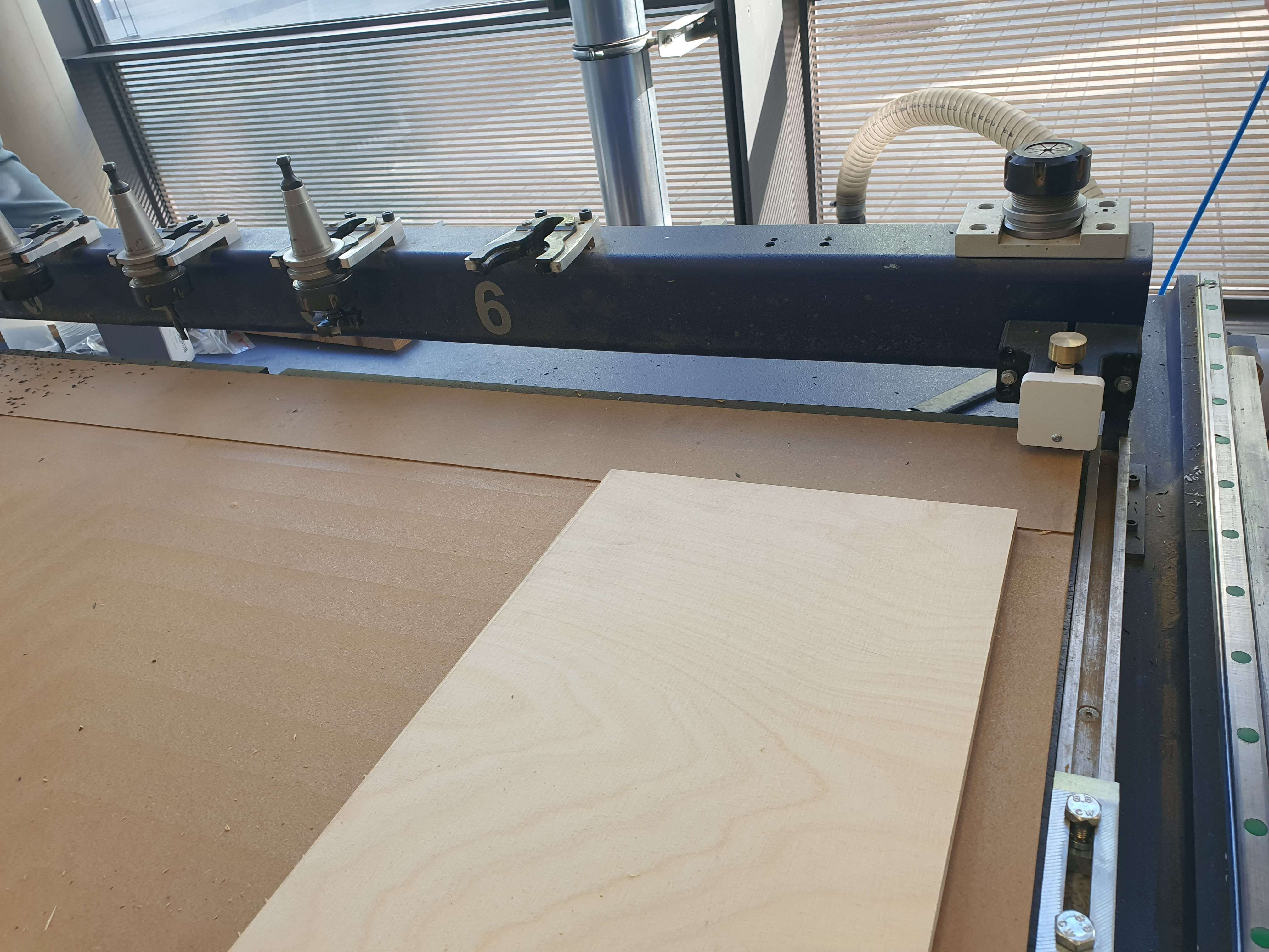
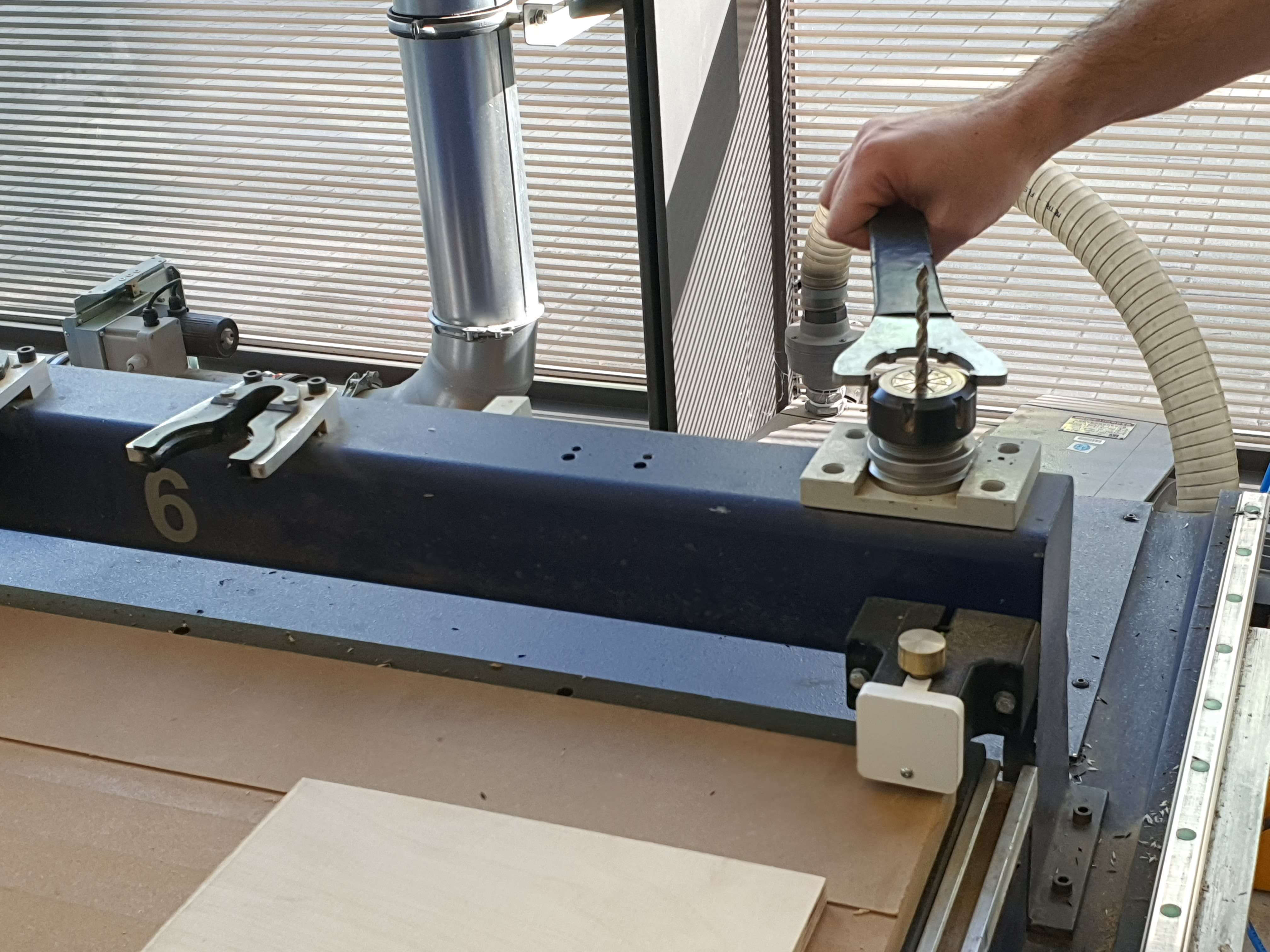
Make sure—and this is extremely important—that the tool is placed in the correct position. Ensure that the tool is flush and secured properly. Also, if the tool has been exchanged for any reason, measure the height of the milling bit inside the holder.
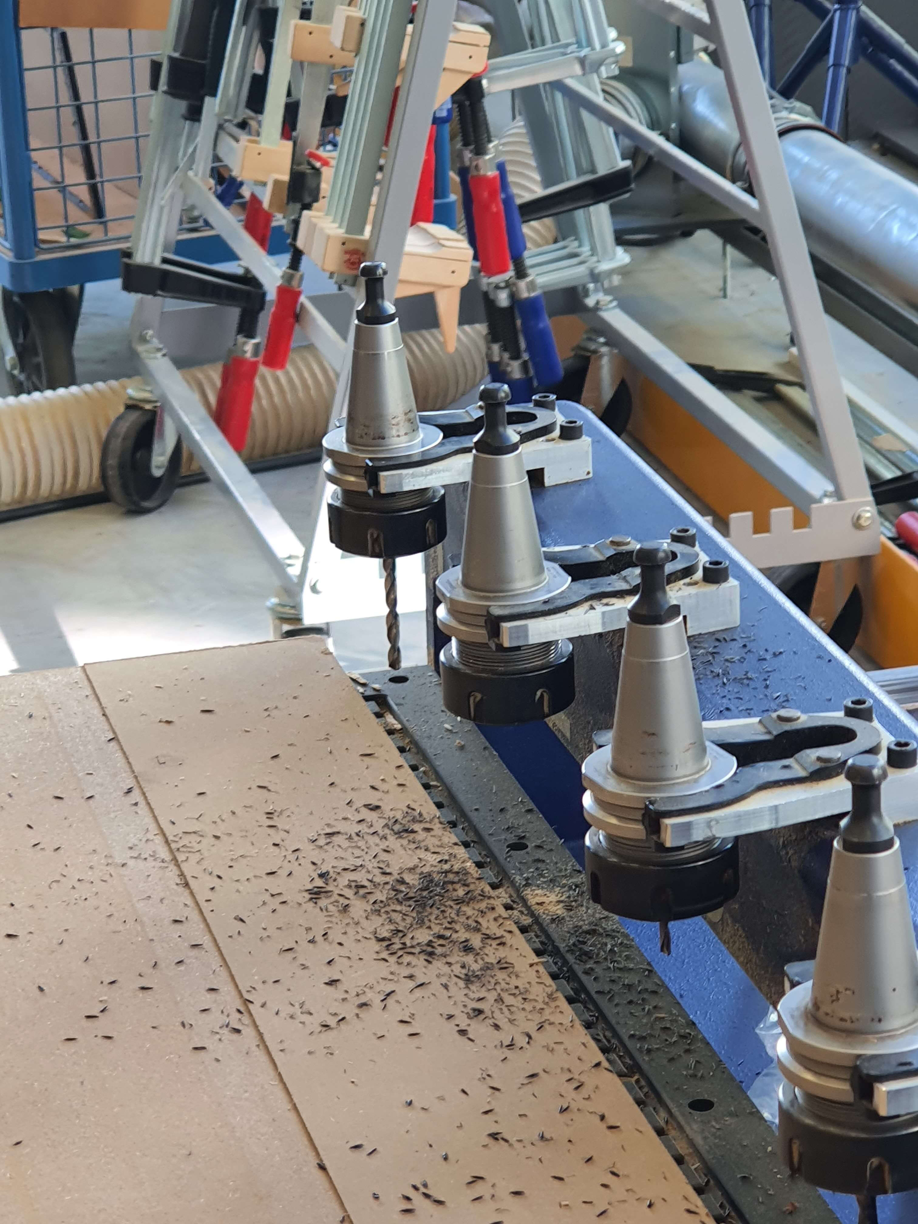
Once the tool is placed and everything is correct, let’s place the material you want to work with. To do this, drive the X-axis back to the tool holder using the remote. Place the material so that it does not overhang any sides of the machine. To hold the material in place, this CNC comes with a vacuum function, which is operated in different sections. Once you are happy with the placement of the material and there is no overhang, go ahead and activate the vacuum pump to hold the workpiece in place. You will find switches in front of the machine. Turn on the sections where your workpiece is located. If you happen to turn off the vacuum pump, wait a couple of minutes before turning it back on.
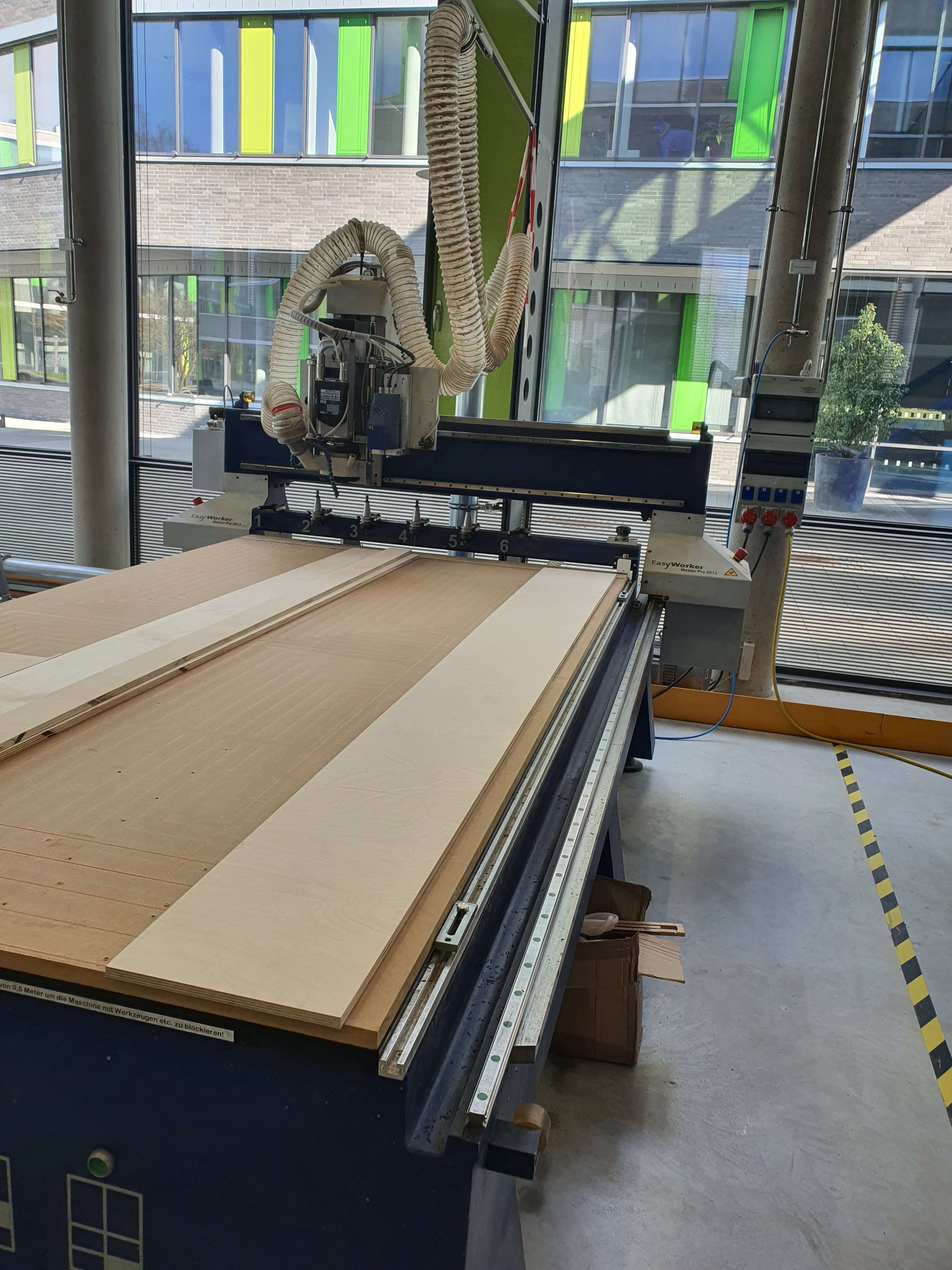
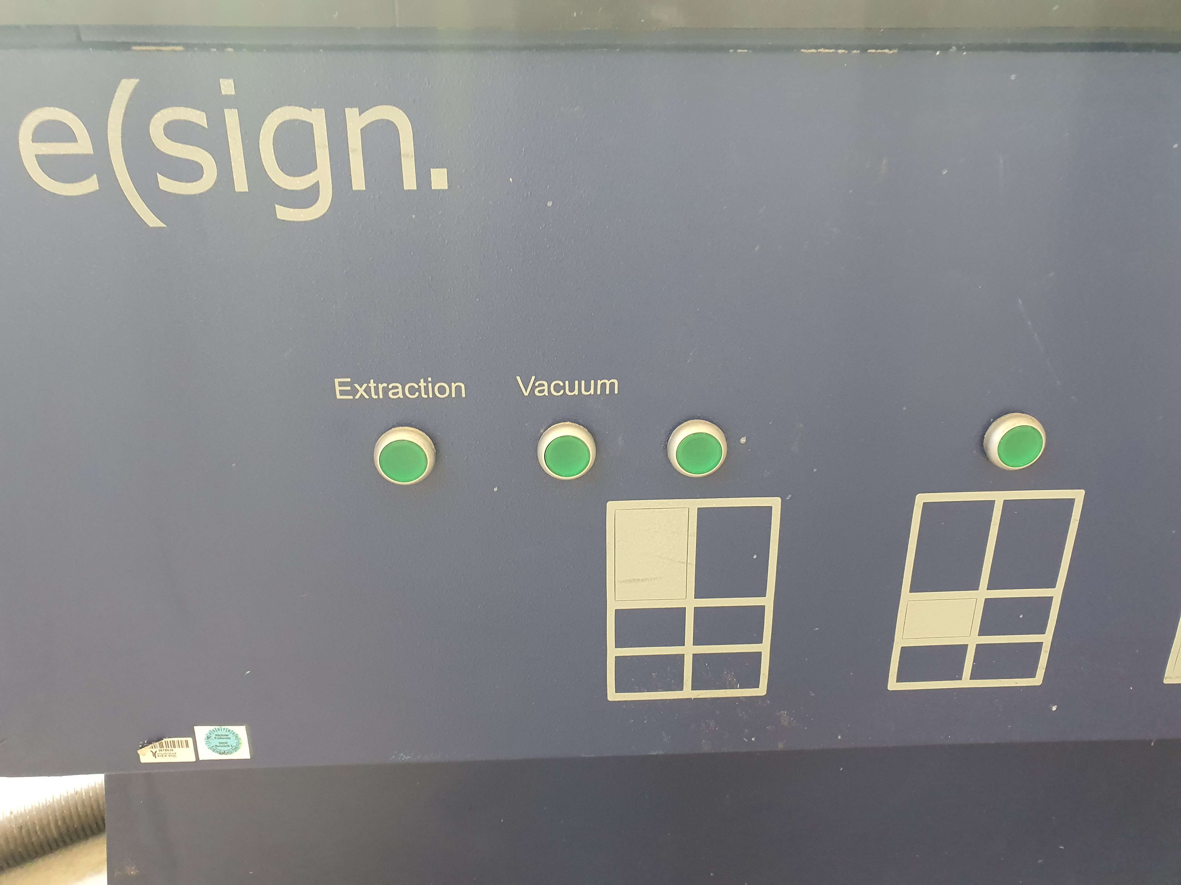
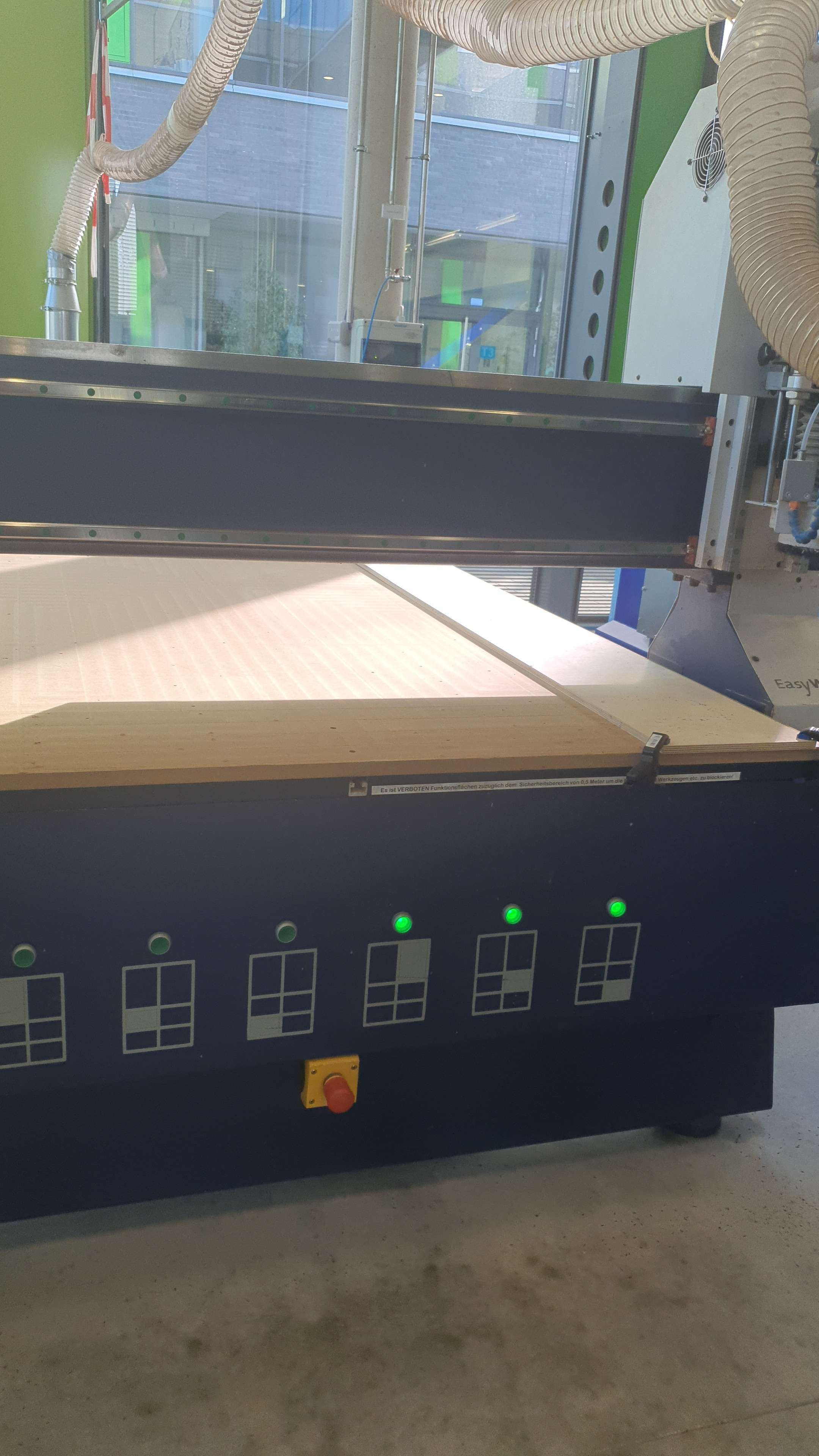
Now that the workpiece is being held in place, we can get started with the CNC functions. Go ahead and home the machine before any cutting or milling takes place. This is necessary because it gives the machine a reference for the X, Y, and Z axes, telling the CNC where the tool is located and, in return, giving the CNC a reference as to where the workpiece is in its machine coordinate system.
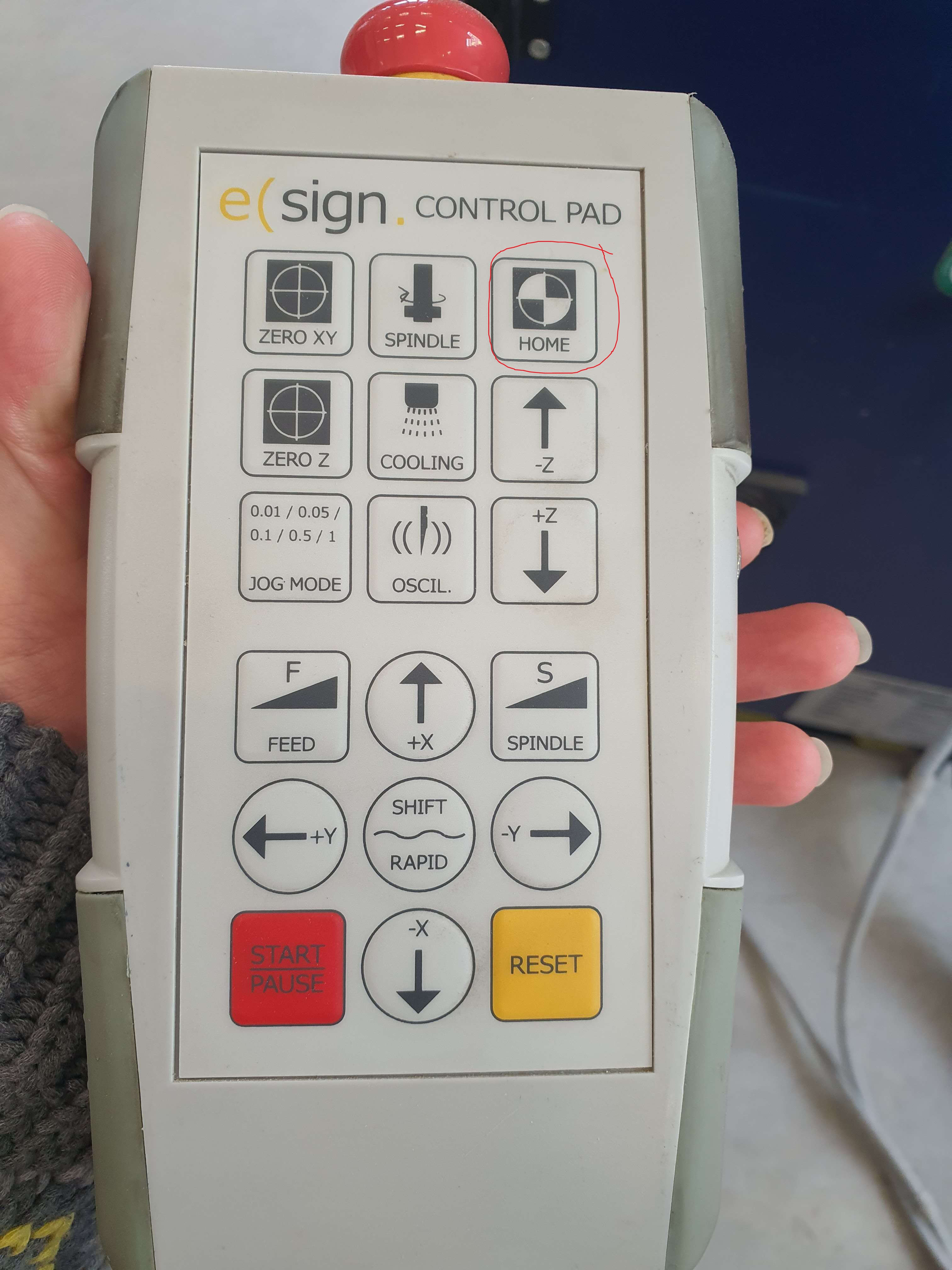
Be careful, as there are two different coordinate systems that can be used. One is the machine coordinate system, and the other is the workpiece coordinate system. Unless otherwise instructed by your instructor, we will set and use the workpiece coordinate system. This is done by uploading the machining code (otherwise also referred to as G-Code). This will tell the machine which tool to retrieve from the tool holder. Once the CNC has the correct tool, use the remote to move the CNC tool to the workpiece.
The first step is to set both your X and Y axis origin. To do this, bring the tool down slowly(red). The increments (steps) can be adjusted on the remote(Orange). Lower the milling tool so that it is 50mm above the workpiece, then adjust the step size on the remote. You do not want to run the milling tool into the workpiece, as this can break the milling bit and damage the Z-axis at the same time. Slow it down to 1mm steps until you are just 15mm above the workpiece.
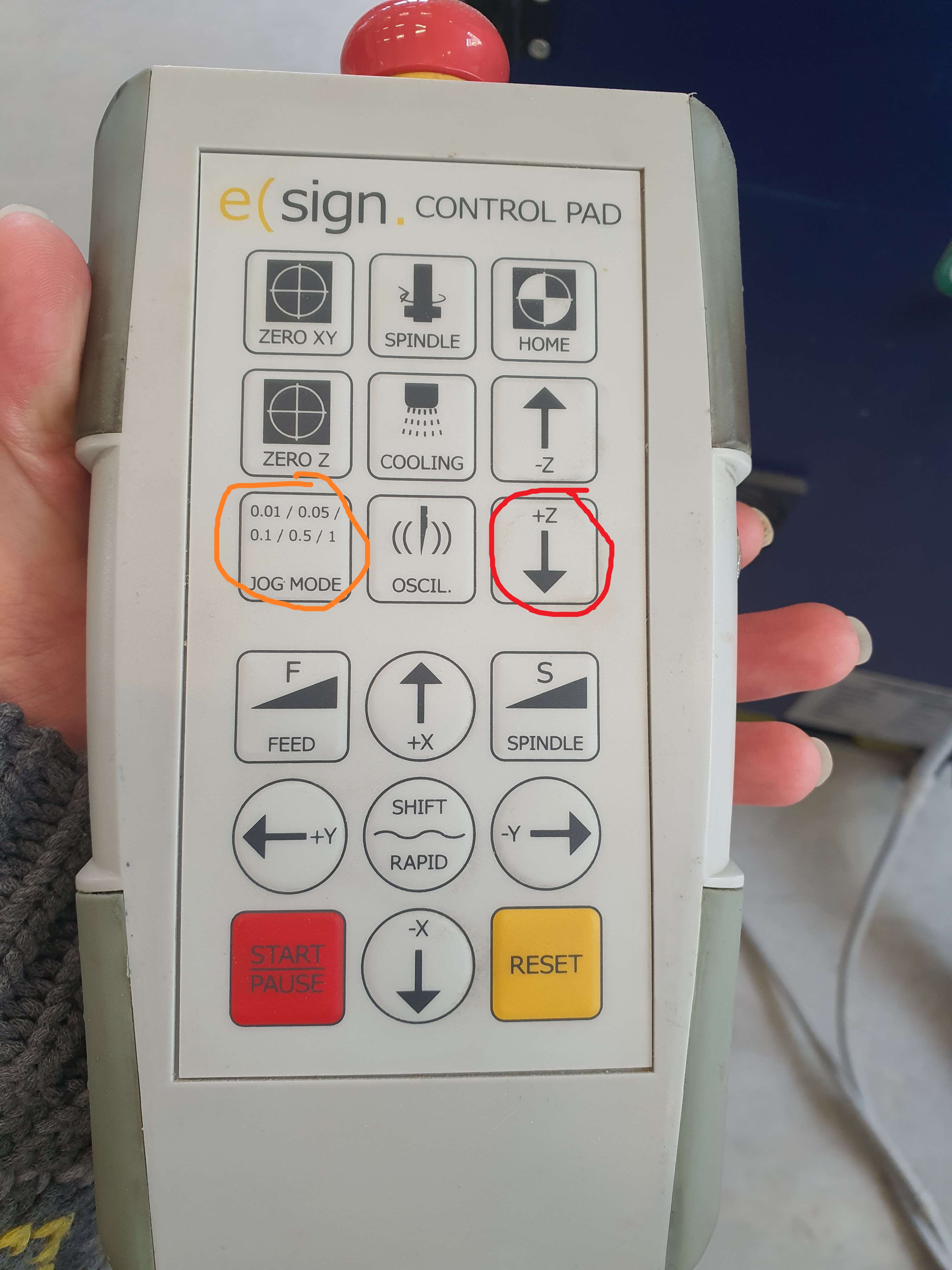
This should be more than enough to set the X and Y coordinates(red). If your milling bit is 6mm, you want half of the tool over the workpiece and the other half over the edge of the workpiece for X and Y. This is enough to eyeball the origin. You should have calculated some waste material. Next, drive the Z-axis up using either the computer or the remote. We prefer the remote. Drive the Z-axis about 50 to 60mm above the work area and set zero-Z(orange)
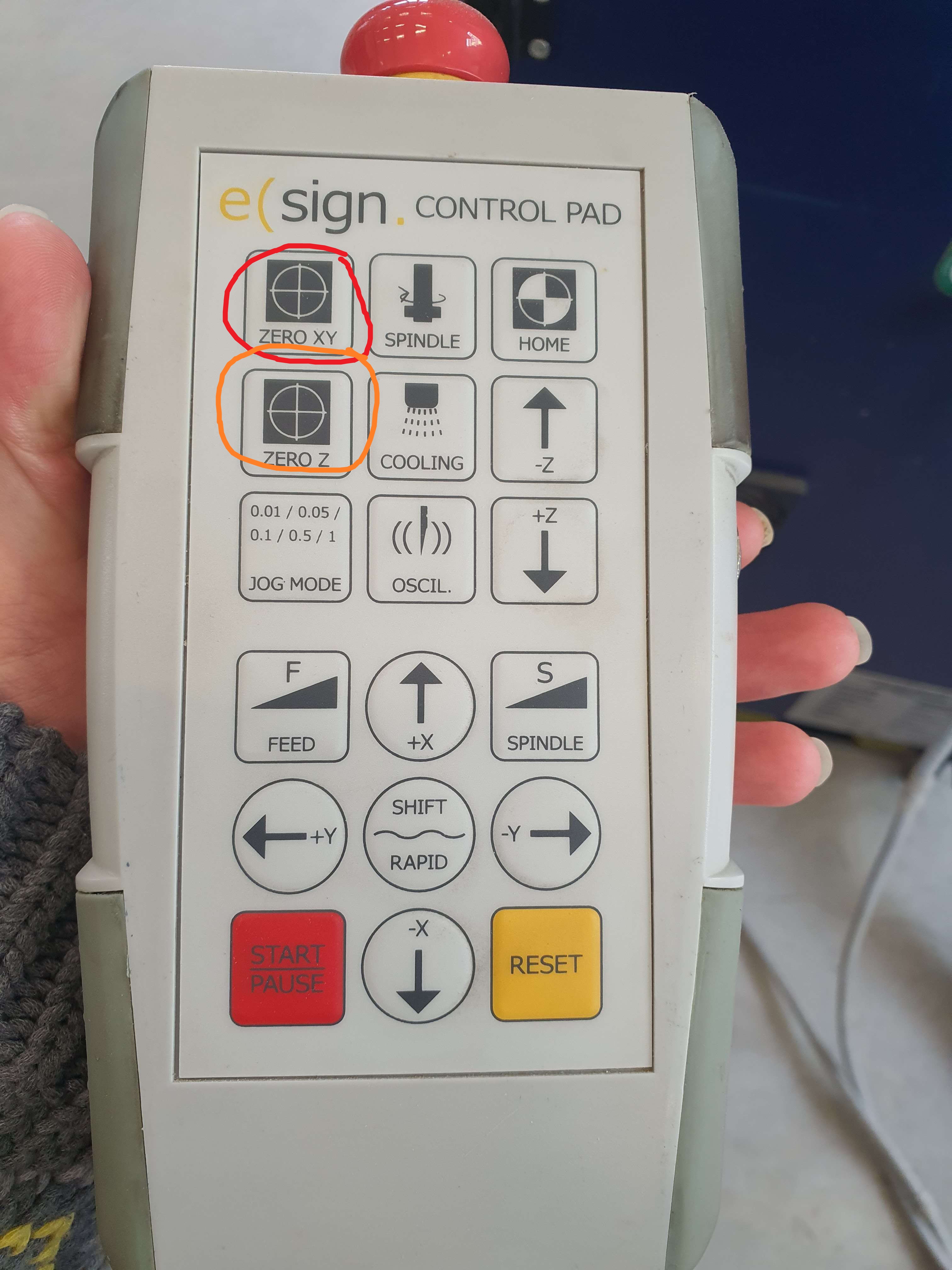
The reason for this is to perform an air cut test. This is done to verify that the machine code does not cause issues, such as plunging into the workpiece or cutting too deep and damaging the CNC bed. This could harm both the CNC bed and the milling bit, as well as the CNC Z-axis.
Let the CNC run the cuts in the air. If nothing unusual happens, we can now move on to setting up the Z-axis to the correct height. Let the CNC return to the set zero point (X and Y origin). Do this using either the remote or the computer. Now move the CNC so that the bit is above the workpiece. On top of the CNC Z-axis is a sensor with a pre-set height programmed in. Place this pressure sensor under the milling bit.
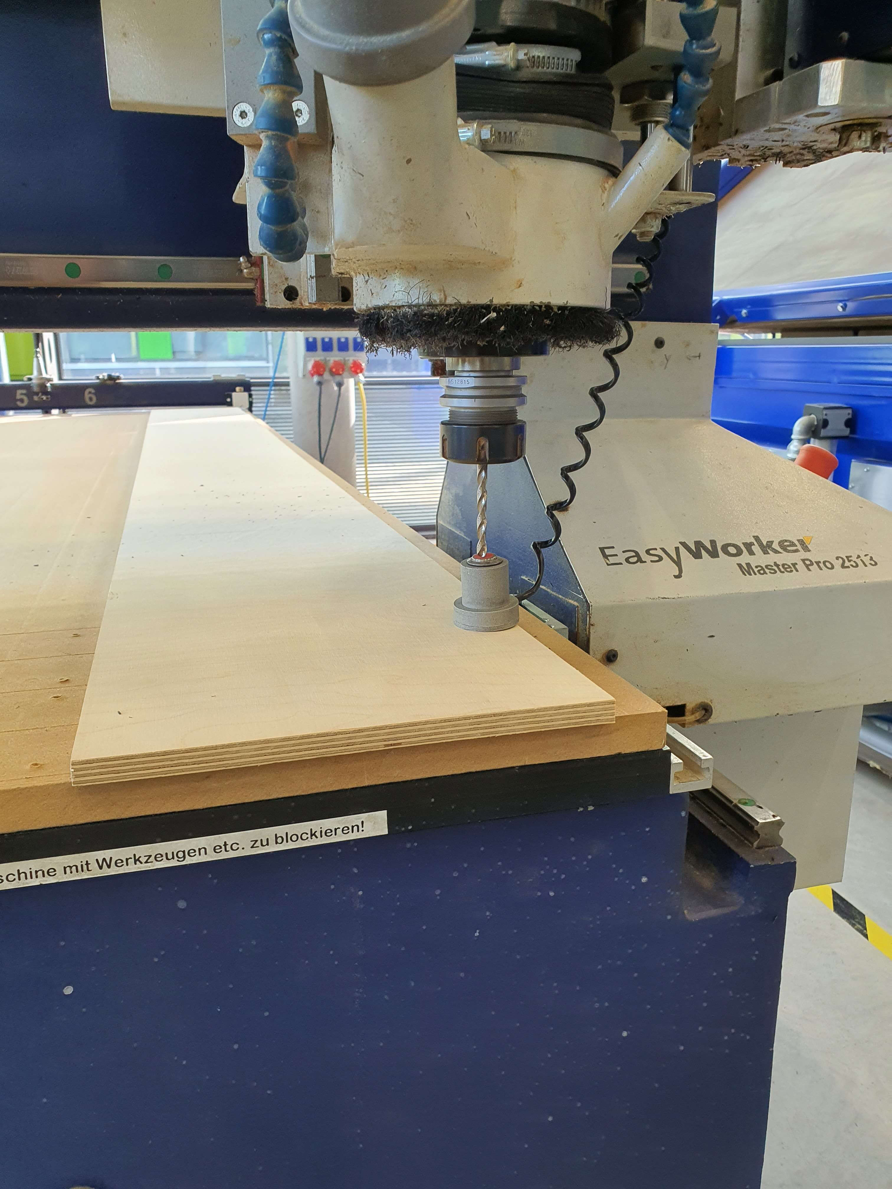
This process should always be done with two people, and you should maintain eye contact at this point since you will not be able to hear each other over the noise of the vacuum pump. Once the milling bit is just above the sensor, keep holding it in place, and let your partner give the command to the CNC to check the height of the tool and workpiece thickness(click as shown in the Image). Once the machine has done this, place the sensor back into its holder. Pull down the dust collection hose.
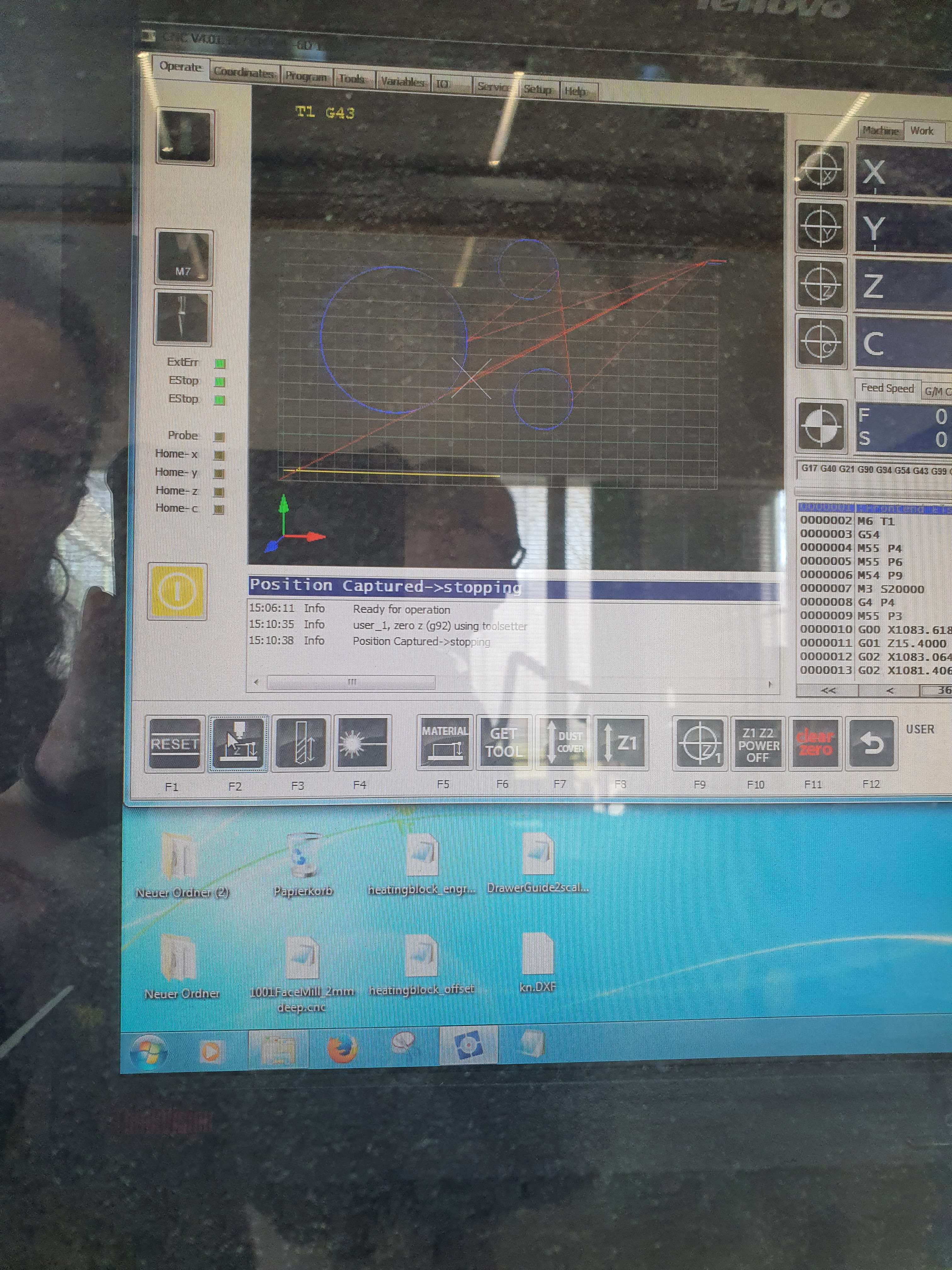
Now, one final step remains—turn on the dust collection system. To maximize dust collection, make sure that all other gates are closed except the one that leads to the CNC.
It is important to note that while milling operations are taking place, you are not allowed to leave the CNC unattended under any circumstances. If something goes wrong or the dust starts to burn, immediately shut off the CNC and the dust collection system using any of the emergency buttons. Notify your instructor immediately after you have extinguished the fire. Open the dust collection system and remove the collection bag in case embers have remained.
Once the CNC has started its cut, stay vigilant, ensuring that you remain outside the marked safety boundaries and that no persons or objects are within the restricted area around the CNC. If all goes well, you should have your parts within a few minutes, depending on the complexity of the design. In this case, we are checking the alignment of the CNC to ensure that nothing is off and that our settings and tolerances are within specifications.
The next step is to check how accurate the CNC is when cutting out the parts. Do the finished pieces have the same dimensions as in the original drawing? Next, check the fit of the part. If done correctly, the part should be able to be tapped into place with minimal force. If this is not the case, the tolerance needs to be adjusted.
Results
Milling the part did not take long, only about 10 minutes. As we used an upcutting tool, the edges were relatively rough. However, a bit of sanding solves this issue.
Milling of this part was performed for the purposes of more than mere demonstration of CNC-based production of a special part. It was also a valuable test of several important machine parameters. Specifically, the operation allowed us to test effectiveness of material fixturing, verify cutting and feed rates appropriate for the task, and, lastly, measure spindle runout, axis alignment, and press-fit finger joint dimension quality of the machine.
Fixturing
Fixturing was done using a vacuum bed, backed up by mechanical clamps for extra security. While the vacuum itself provided sufficient holding force—observed in that the part did not shift even when hit from above at an angle—the use of extra clamping is considered best practice to eliminate any chance of material movement during machining.
Spindle Speed
In milling, we reduced spindle speed gradually manually from 20,000 RPM to 15,000 RPM in an attempt to optimize cutting performance. Based on the resulting acoustic response, however, the adjustment was adverse. The spindle made a much harsher, unstable sound at low speed, typical of unfavorable cutting conditions—most likely due to increased tool deflection or inadequate chip evacuation. We responded by bringing the spindle speed back to 20,000 RPM, which restored a smoother, more consistent sound of operation, signifying improved cutting efficiency and machine stability.
Alignment
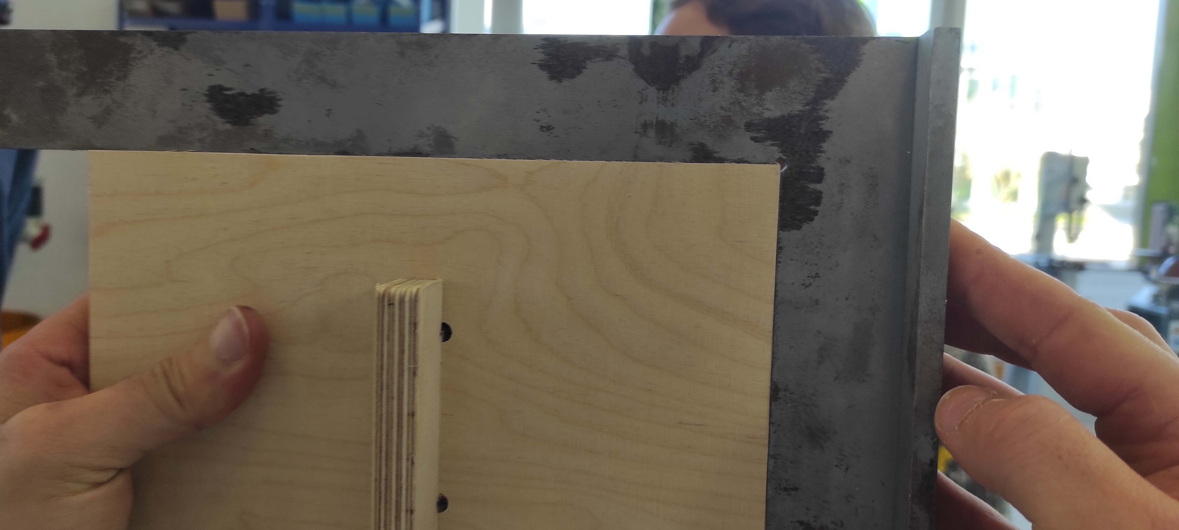
Alignment testing included verifying that the axes of the CNC machine are perfectly orthogonal, such that a rectangle in the drawing is accurately duplicated as a rectangle in the milled product. To verify this, we used the two perpendicular sides of the main section of the test piece and a machinist's square—a precision "L"-shaped tool with a known 90° angle. By positioning the square against the machined corners and observing any gaps or light leaks between the tool and the workpiece, we would be able to determine departures from true perpendicularity.
There was no light seen between the test piece and the machinist's square in our experiment, indicating a tight fit with no apparent deviation. We can therefore determine that the X- and Y-axes of the CNC machine are properly aligned and orthogonal.
Joint Tolerances
During CAM for this test piece, we defined the tolerance to be 0.01 mm. Hence, for a loose fit, the tolerance must be increased.
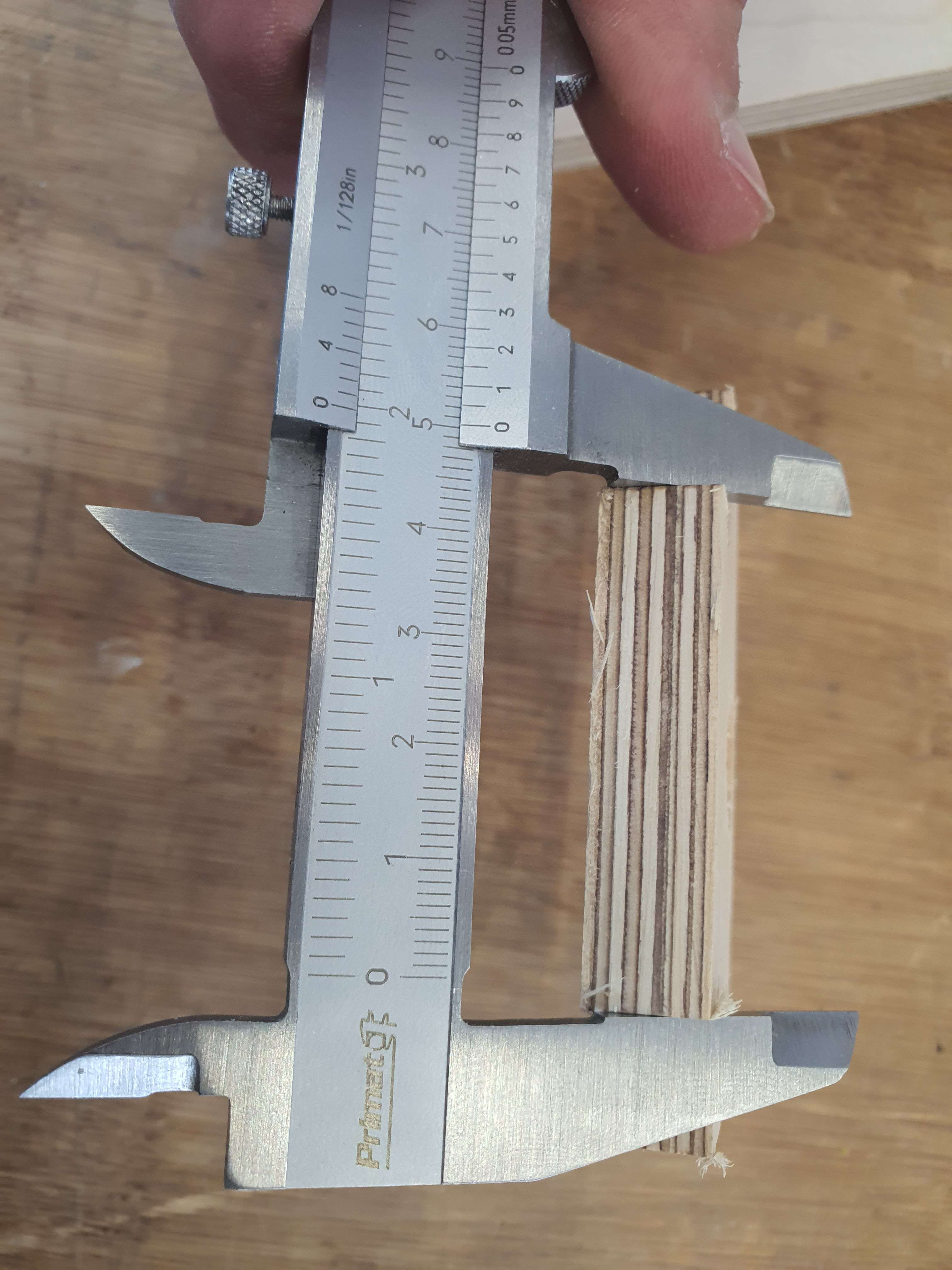
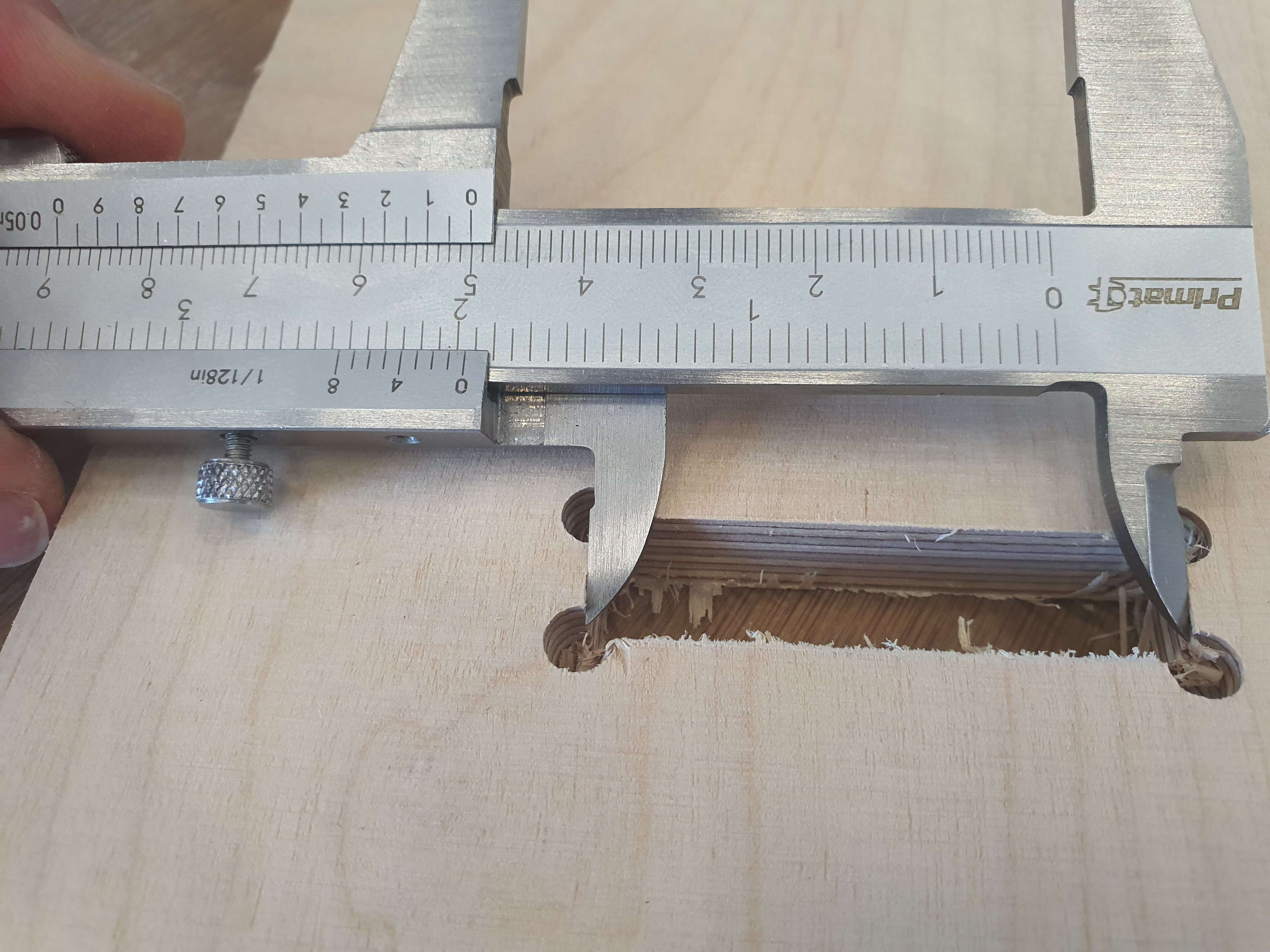
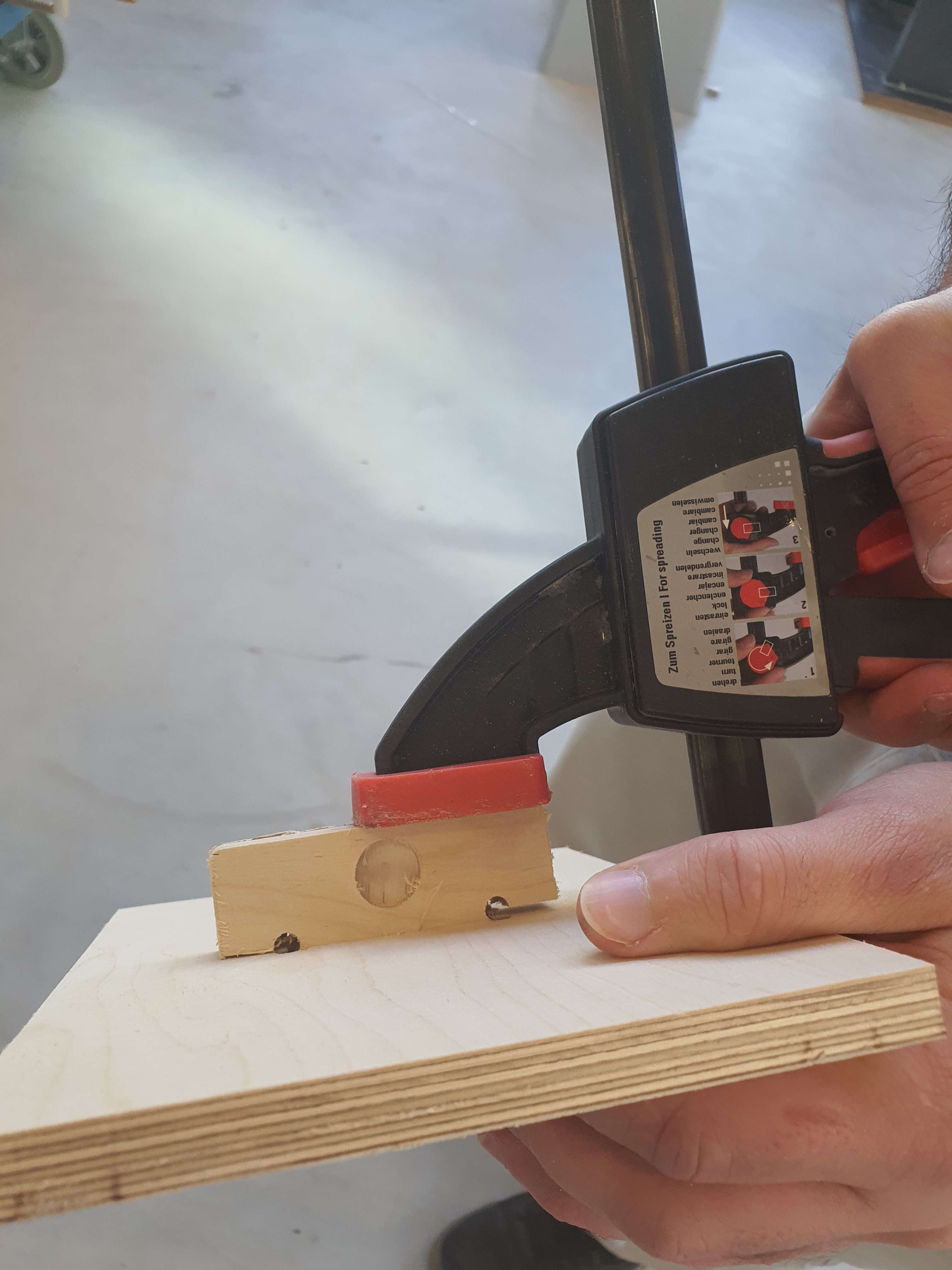
To test the tolerance we put, We assembled the two pieces with the help of a Clamp because the two pieces were not be able to join just with bare hands. The Slot had a length of 50.1mm and the actual "key" had a length of 50mm. With this results, we can conclude, that for a pressfit this tolerances are good but for a looser fit, you need to increase the tolerances.