2. Computer Aided design
This Week i worked on 2D and 3D Drawing/Modeling
2D-basics
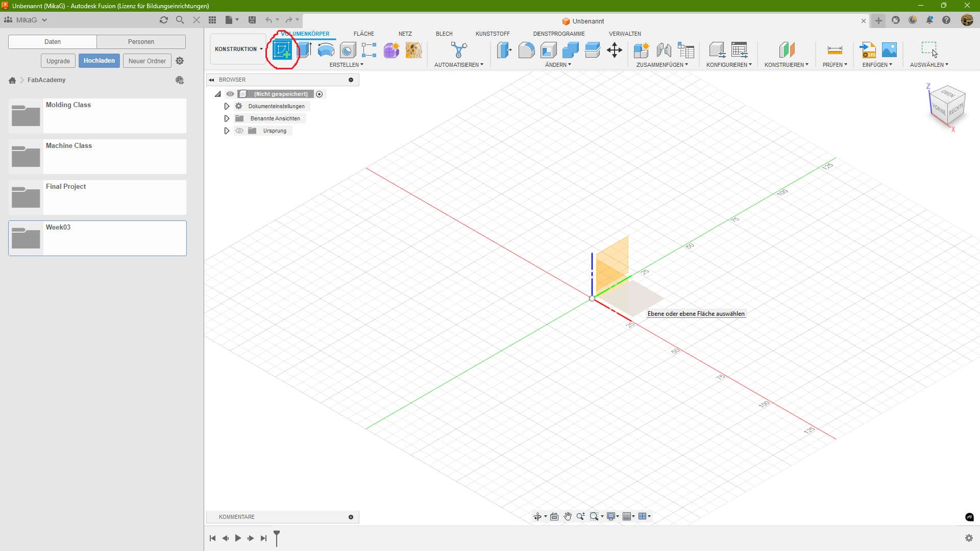
The first Step is to make a Sketch. For that you click on the red marked button and then on one plane of the room
Shapes, Lines and Splines
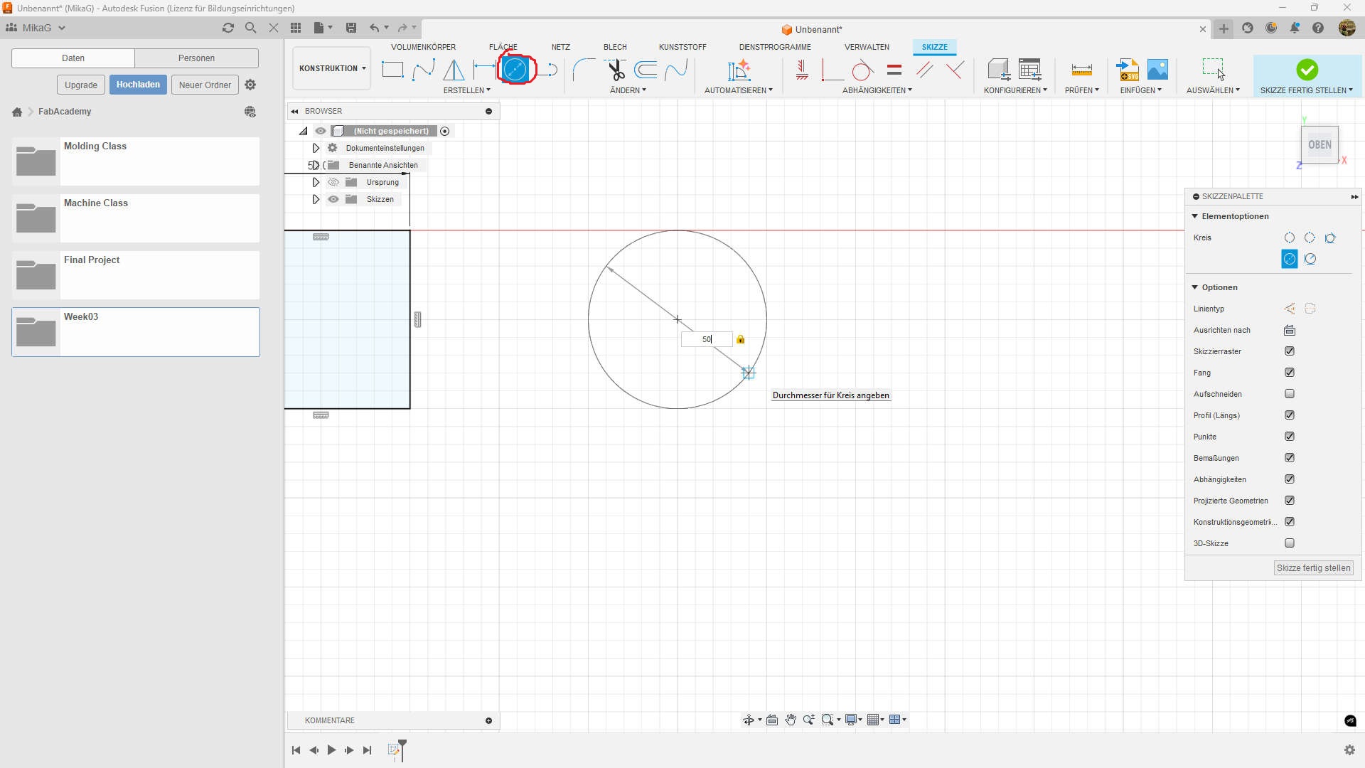
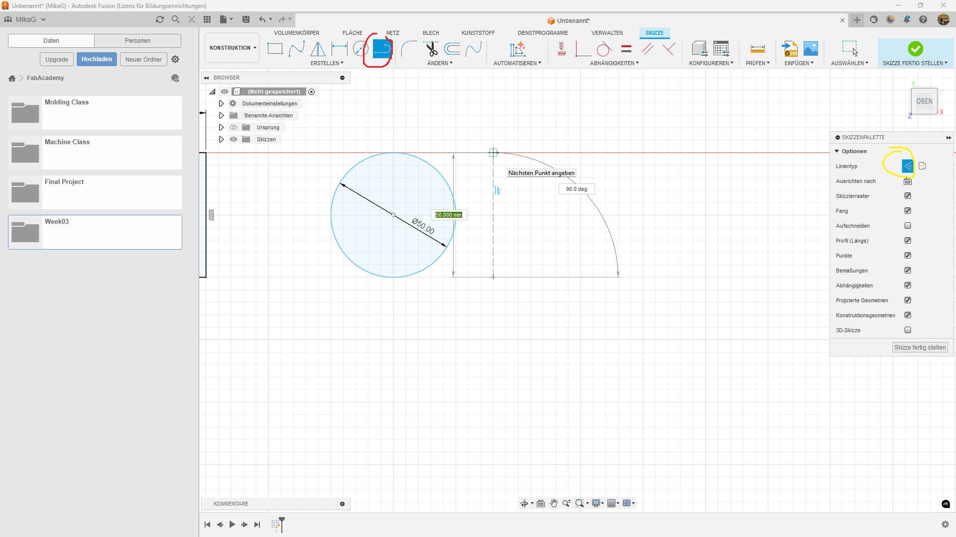
I start normaly with one of these for things. First the circle. In this case i used the centerpoint circle found in the top bar(red circled). After placing the the centerpoint you either can click somewhere else to set the radius or enter a custom radius
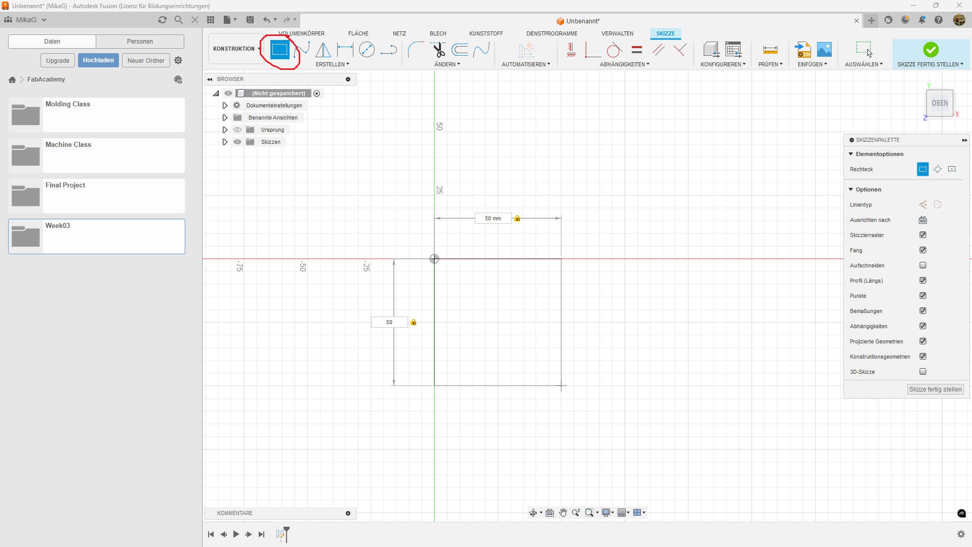
the second shape i normaly use is the rectangle with 2 points(red circled). just click somewhere to set the first point. The second point can also either be set by entering the length of the two sides or by just clicking some where.
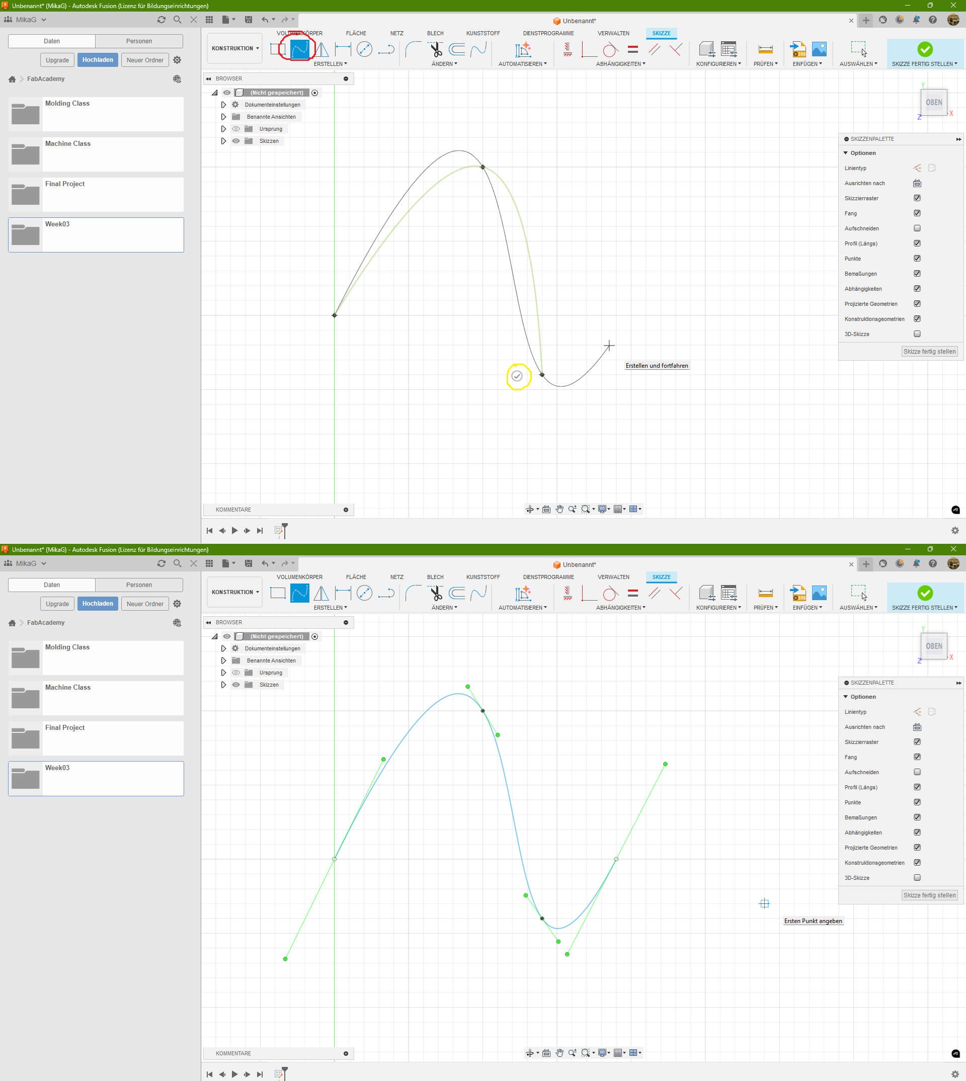
Splines(red circled) are great for making unique or organic shapes. Just click somewhere in the sketch to start the spline. you need at least 2 points(start point and a second). In my example i went with 4 points. Splines are created in first place by setting points, which the spline should touch. After setting my points, i can accept (yellow circled) them and see, some different bars. They are used to set the incline of the spline points and also the direction where to go.
last in this category is the actual line(red circled). I also made it a "helperline"(yellow circled). to place it, you can either set two points or set one and enter length and angle.
Manipulation
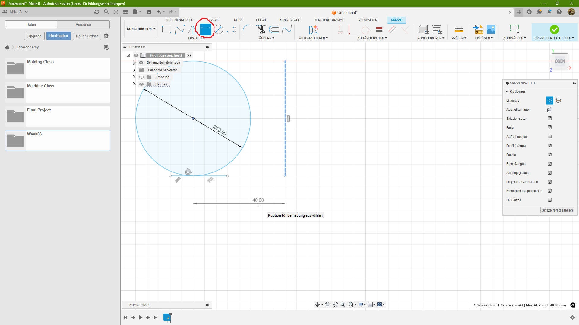
First in the Category I show the "sketch Dimension"(red circled). This is helpfull, if you need to either enter Dimension, you forgot or you want to add afterwards. In my case i wanted to change the distance between the circle and the helperline. After selecting the line and the centerpoint of the circle i entered the dimension.
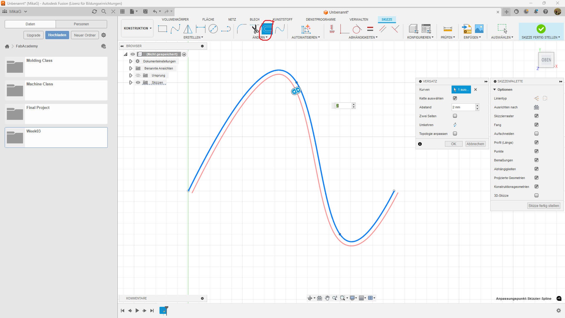
An Offset(red circled) is used for example to create a channel with a specific shape, or to create tolerances. just select an object and set the dimension. you can also set in negative numbers to invert the direction.
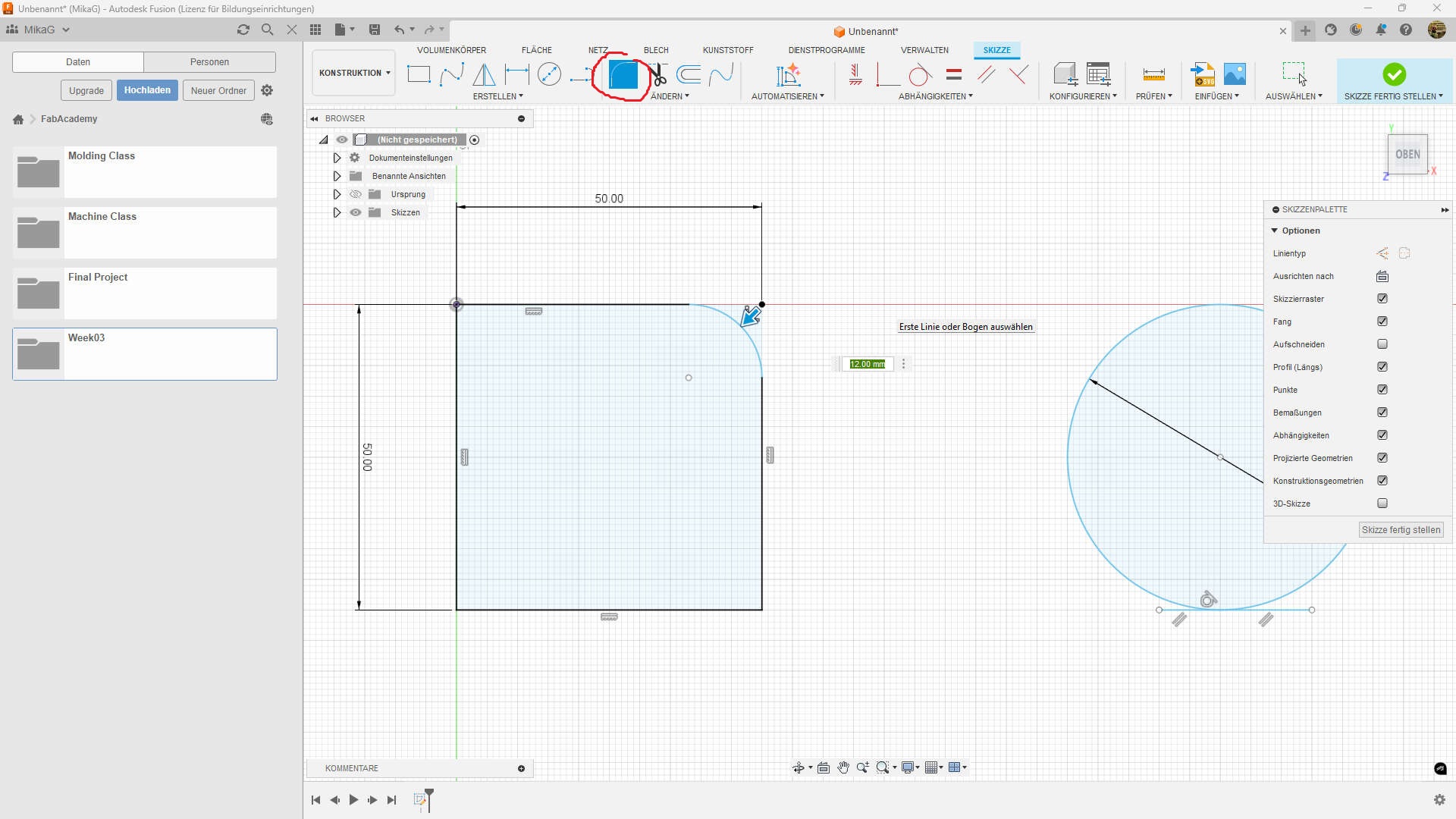
the last thing in this category is a fillet(red circled). either click to connect lines or the edge point and enter the radius.
Duplication
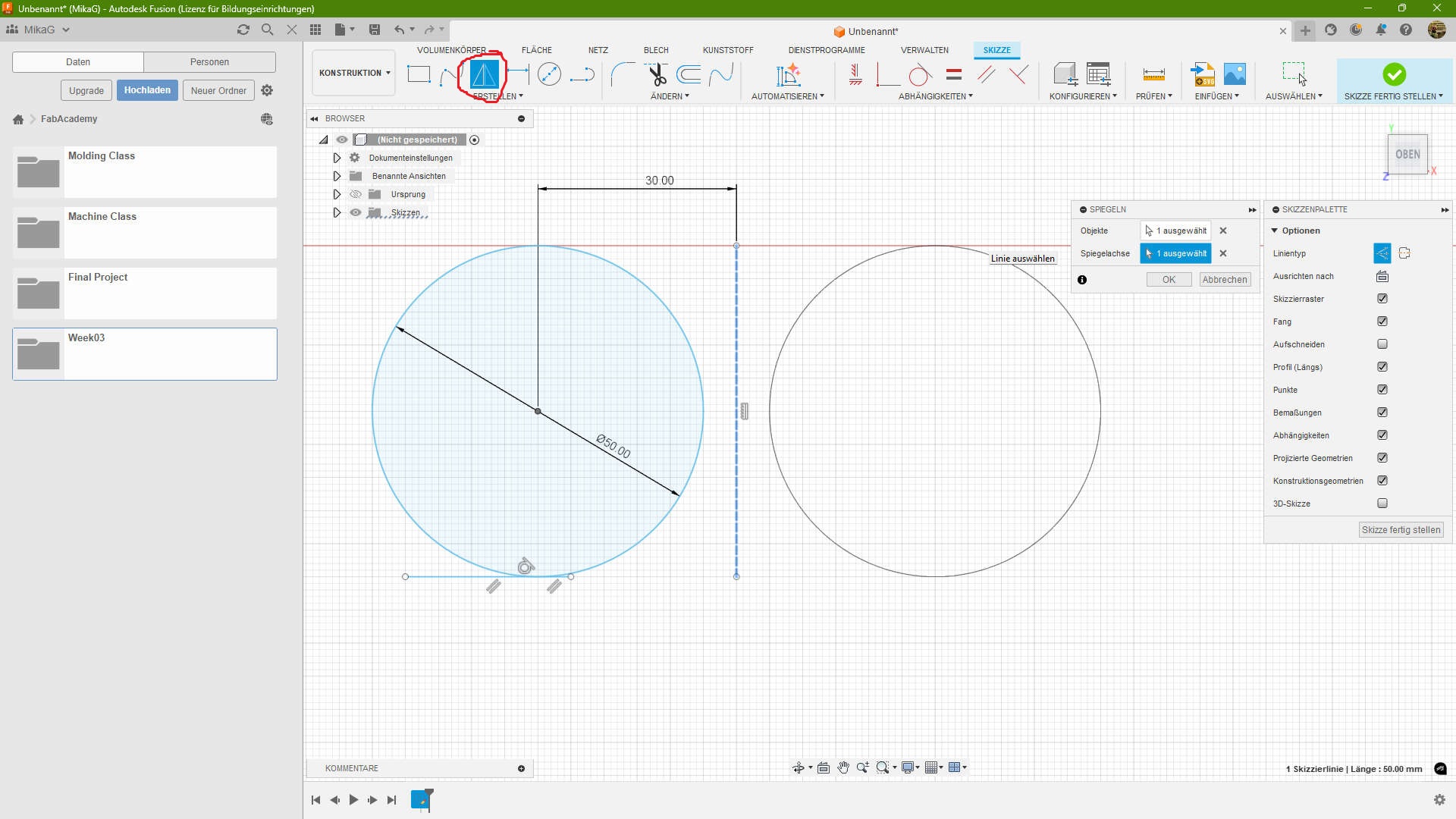
Mirroring(red circled) is simple. You need an object to mirror and a line which acts as our mirror. I first selected the circle as my object and then the helperline as mirroraxis.
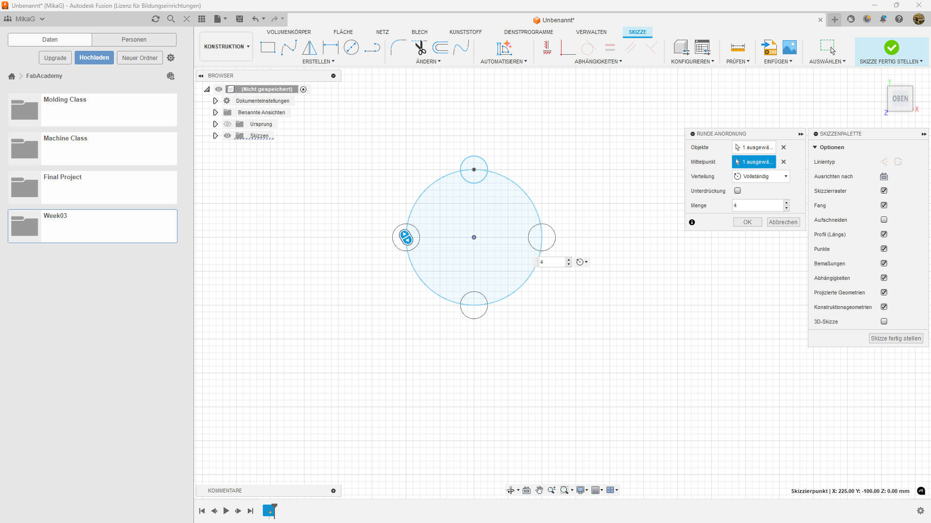
Patterns are amazing. There are circular and rectangular patterns. You find both under Create -> Pattern -> prefered Pattern. the circular pattern lets you select the objects you want to multiply, then the center point where to revolve around and then the number of copys.
 #
#
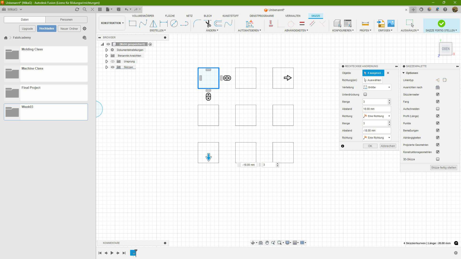
With the rectangular pattern its a bit different. you select the objects, then the directon you want to extend, with the length of the extension and the ammount of copys.
Constraints
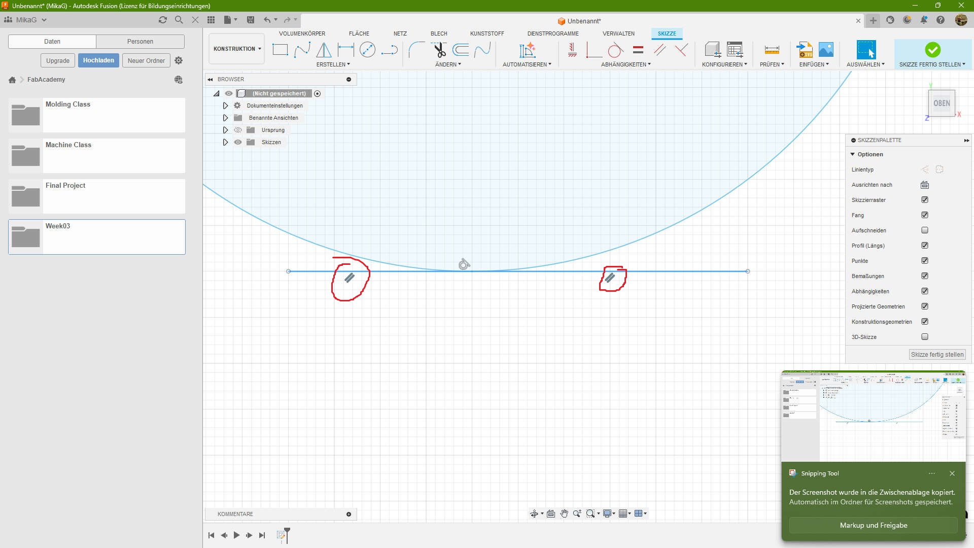
The last thing i want to talk about are Constraints. Here are 3 examples. The first I choose ist the Parallel Constraint. It means that two lines at ever point have the same distance, even if they touch. This applies, espacialy if you extend them indefinitivly.
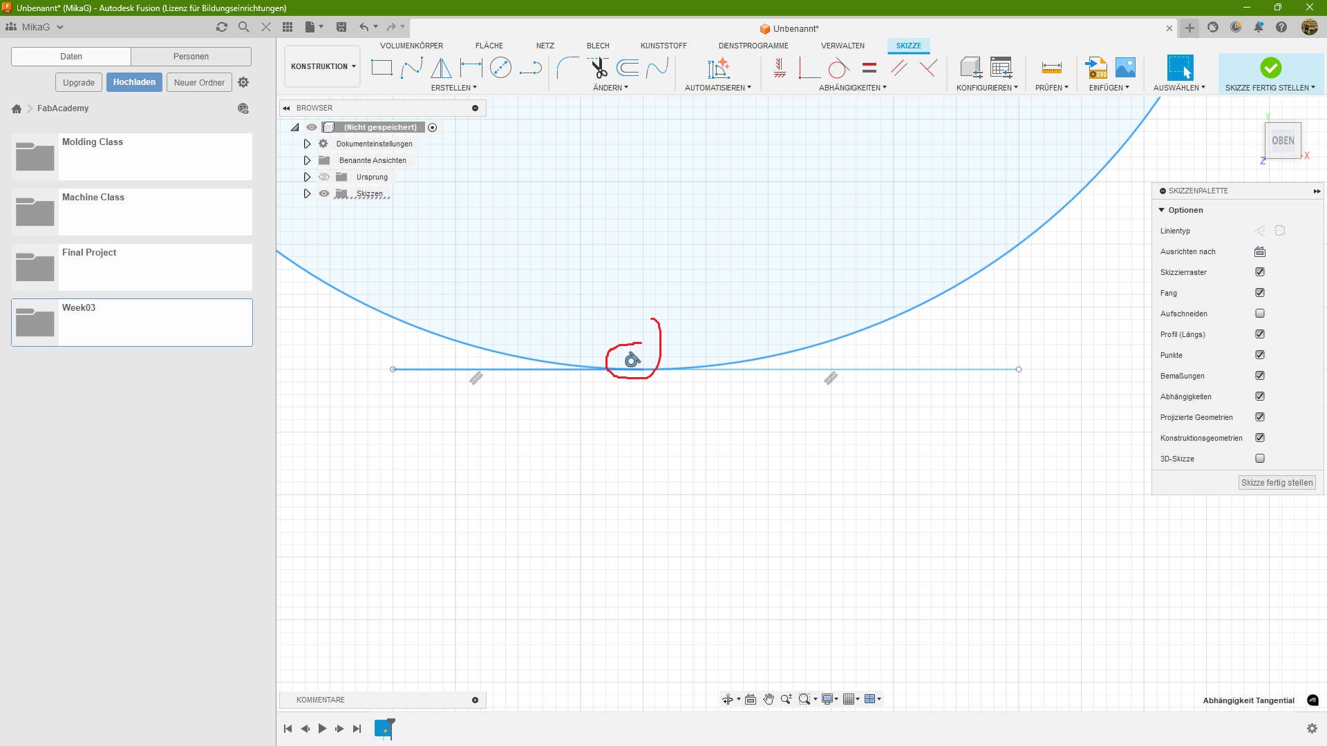
If you have a circle and the line, and they touch just in one spot, you have a tangente
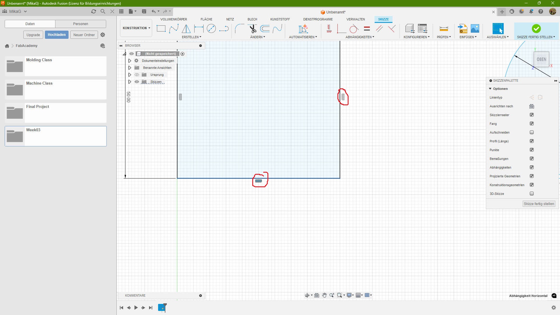
The last constrain, is Horizontal/Vertical. This means a line is parallel to the y, X or z Axis.
3D
For the 3D Part I use Fusion(former known as Fusion360). I tried Onshape and FreeCad in the Past, but non of them catched me. Could also be, because i started with Fusion at "young" Ages. I realy like the UI and the for me its easy to use. Also what i like is the Combination of Cloud and local working. FreeCad is a Complete local solution and Onshape is Cloud based. So Fusion is the best of both Worlds.
Modeling
I started to try to model a mechanism, wich is used in retractable ballpoint pen's, but after the second Attempt, I got new Input. I discussed it with my Mentor, which took us around an hour to think about a solution and we came to the conclusion, why dont use a "twist-lock" mechanism
While working on the Docu i realized what a complicated part this is to write over XD.
1. Attempt
This Video was sped up. the original is 1hour. For size reason i made a 30sec time-laps out of it. I would recommend to change the speed in the player to x0.25
First I started by making a Sketch and Creating a square with 25mm side length (~1"), which is the standard size of a tile in Dungeons and Dragons. Followed by making an Extrusion of 15mm of the outer ring of the Square. On top of The Square a new sketch was made, where i projectet the Outerring to use as Refference for two circle with d=5mm and d=7mm the outer diameter was used to make a Ring of h=5mm positioned in the middle of a 15mm pillar. I also added a cap to make it a Tile with walls. After that i rounded the edges of the tile.
At some Point i realized it is a bad idea to directly attach the Centerpin to the Tile, because if i would twist the pin, it would twist the whole Tile which would break it. Which i solved with a screw, which connects the pin with the Tile. I would screw it loosely to allow it to swivel. Another Problem accured at this point. I need to make angled Cuts. So i first removed the pilar, divided the ring into two parts and made a helper sketch at the top of the ring to made angled Planes, which where then used as tool to make plane cuts for the teeth. In the Video you see me going back and forth with the pin in the middle this is part of my design thinking Process, where i try and fail and redo and all over again.
Halfway through, you see me making some more teeth this time i wanted to make 4. Two long and two thort one. I thougt that would be enough. The teeth of the pin would go up and down and twist if i would push the shorter once. At that point i scraped this idea and started with a new interior
2. Attempt
Same with this Video. I would recommend to change the speed in the player to x0.25
What did i've done different here? I made 8 possible teeth and added a Housing, which then should be housing a spring to create a force which would then let the main pin slide on the teeth to twist and change the position. The tricky part here now was to get the spring inside. For that i would just print a couple of teeth seperatly to glue them in at the end.
Final Attempt
Same with this Video. I would recommend to change the speed in the player to x0.25
For my final Attempt i started with a cut in the top of the tile. Followed by a plane which i made through two oposite faces. This plane was used to make a sectionview and a sketch, on which i created a print in place swivel. The advantage is, that i have a nice possibillity to let the pin turn without assembly and adding more parts. It also prevents the pin from escaping the tile. To make this swivel i just revolve the two parts of the swivel around a drawn centerline.
After the swivel was done, i made the Guidepin and the Guiderail. for the Guidepin, i just made a hole at the end of the centerpin, where a piece of Filament will be added. For the Guiderail i first need a housing. For that i just made a cylinder and a sketch for the rail on the plane where i made the sectionview on. after i made the sketch with a bunch of recatangles, i just revolved them by 20° and -20° to create the lifting rail. For the locking part i revolved the top rectangles by 90°.
The last part was to add a detail which let me turn the pin and something where i could screw the Housing to something else. The first part was just 4 groves which are chamfered to allow the counterpart to be seated correctly. The second part was were two wings with a holes, that then were extruded to accept a swall 3mm woodscrew.
Download the f3d archiveRender
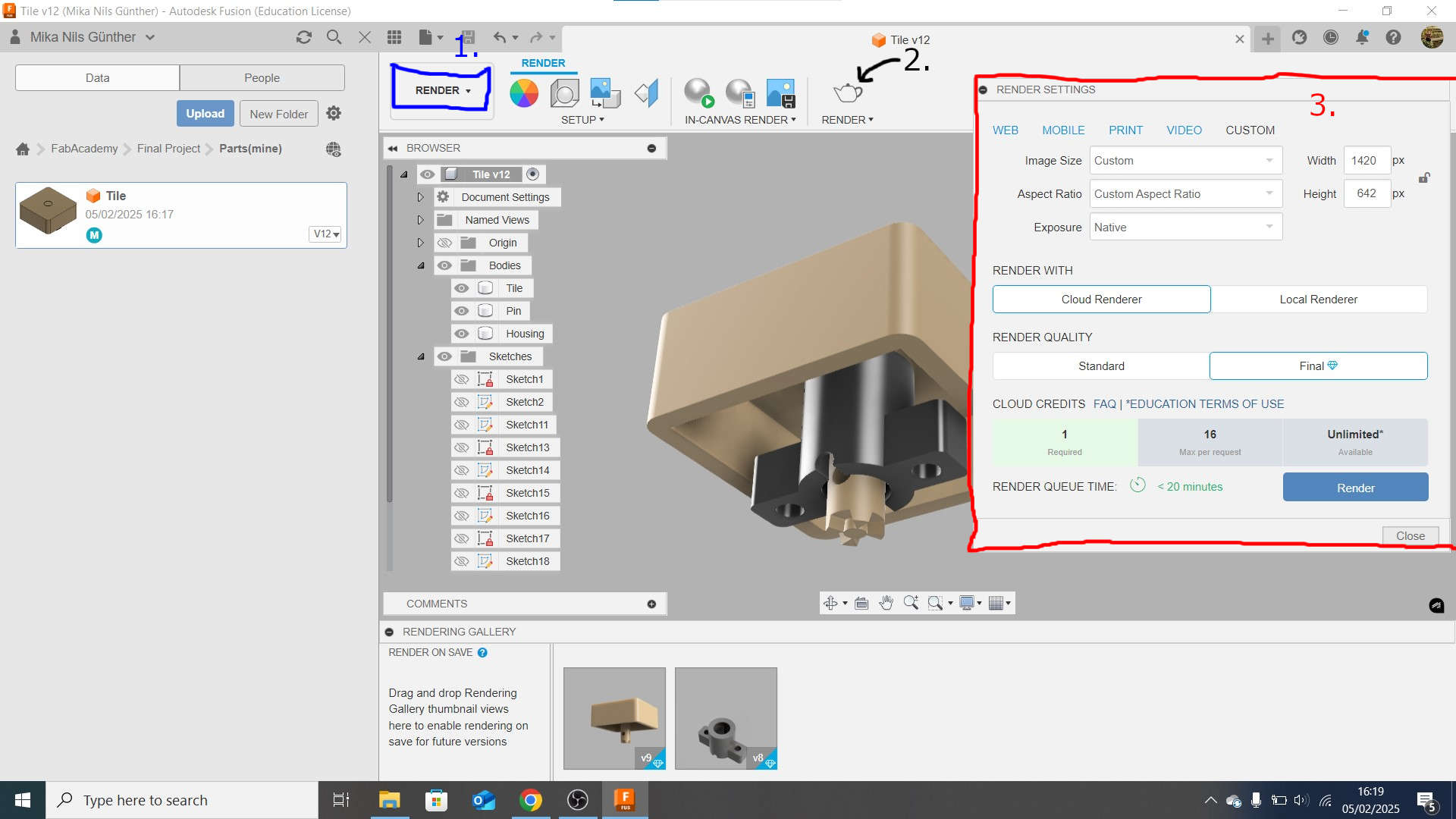
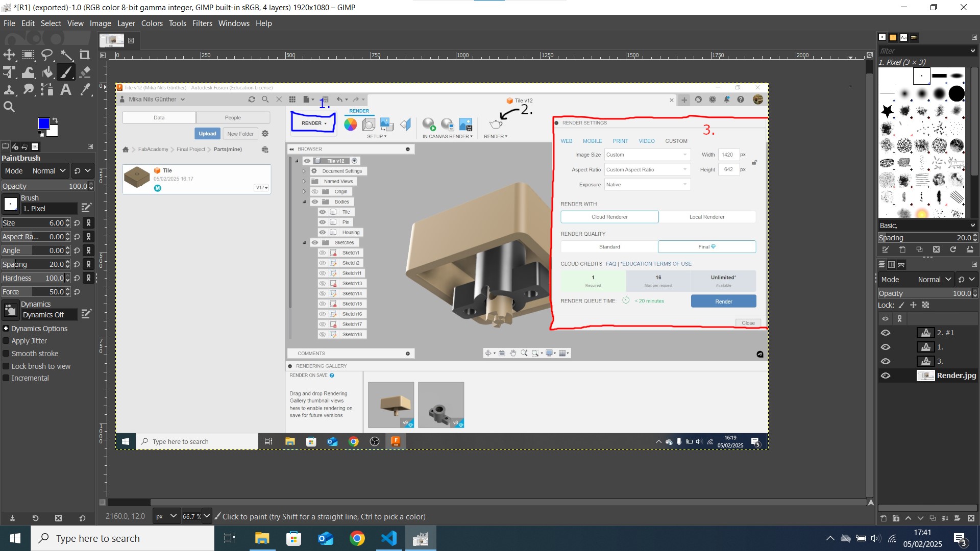
Rendering in Fusion is realy simple. You just need to go to the Render View(1.), move the view to an angle you like and click on render(2.). After that there is a prompt where you have some settings. I'm using the Education Version of Fusion, which grants me acces to the cloud rendering. I used this, so i can use my computer while the Render is made in the cloud. Rendering in the Cloud takes longer, but as i mentioned it, i can use my computer to work on other things. The animation for example. The Image size and Aspectration in the custom menu is the default setting and represents your current view in the render-tab in fusion. This time i used the default, because i edited the image afterwards. After hitting render i waited and waited and waited. As soon as the render was finished it showed up at the bottom tab and i could looked at it by clicking on it and downloaded it in that menu.
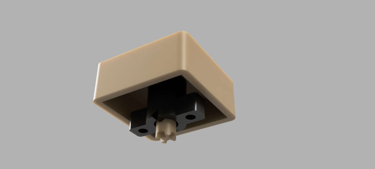
The Result
Animate
As well as the Rendering, Animation in Fusion is very simple. Just go to the Animate Tab like you did with the Rendering Tab before. In the Rendering Tab you can move the timecourse (the block with the line at the button) to a specific timestamp. After you've done this, make a change(transform a component or move the view). This sets a keyframe. Now its just a matter of setting keyframes. The movements at the end are all calculated by Fusion. At the end, click on publish and set a location to save the animation and you are done.
The Result
2D
Vector
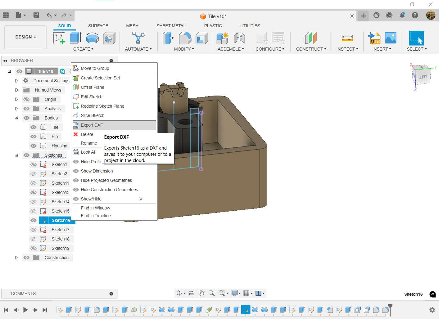
So. I made it very simple for me. As you saw in the 3D-modeling part, i already did vector drawing aka sketches. What i then did, was to export one of the Sketches as DXF. For that, just rigth-click on a sketch and export as DXF.
After that, I just opend the DXF in Inkscape, went to file->Save As.. and saved it as SVG. What you can download now is the SVG of the Guidrail for my locking mechanism
Guidrail.svg
Raster
For working with raster-graphics, i use Gimp. Also a tool which i already know and its open-source.
in fabacademy, my main tools in gimp are the brush, in that case i used it to draw the rectangles around the different areas in the picture and the the Text tool, which is used to make the numbers.
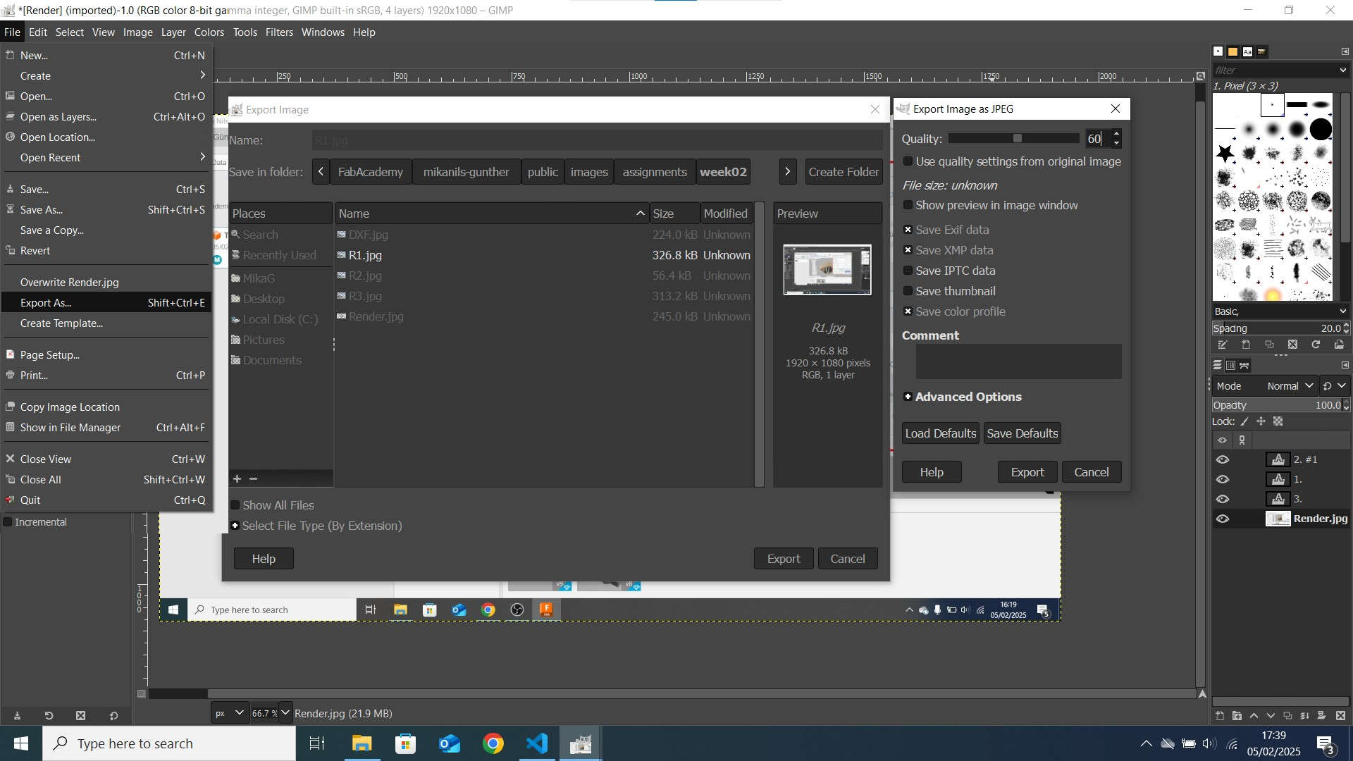
For exporting and compressing i go to file->export as. Then a prompt apears, where i was chose a place to save the picture and to give it a name and set the file type. After i've done this a second prompt appeared. Here i chose a quality of 60 and rest default.
Video
Recording
To Record my screen, I use OBS(OpenBroadcastSoftware), This is the only tool i know and i used it alot in the last Time. But First I needed to set up OBS.
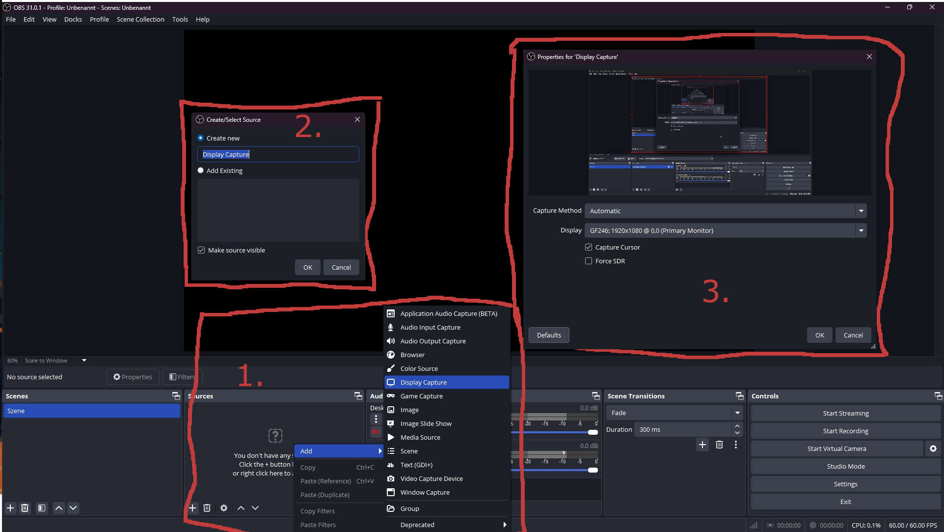
- Rigth-click inside the Sources Tab -> Add -> Display Capture
- Enter a Name in "Create new" and click on ok
- Select a Display and click on okay. I left the rest on default
- I could start recording by hit start recording
- Also stop the recording by hit stop recording
Editing
In my sidepage about VideoEditing i showed, how i edited, rendered and compressed my Videos