Week 9: Output devices
Assignment
individual assignment: Add an output device to a microcontroller board you’ve designed, and program it to do something.
Group assignment: Measure the power consumption of an output device -> it can be found on our group page.
What I did
-
I used the board that I made during week 4 and the code that I did during week 6 to switch on and off a vacuum pump that I will use for my final project.
-
I used the board that I made during week 8 and I programmed it to send analog signals to pressure regulators.
Vacuum pump as output device
For my final project, I will use a pump to vacuum the inside of a membrane, in order to compress layers embedded inside this membrane, resulting in a change of stiffness of my pneumatic actuator (see layer jamming explanation on my project page).
The idea is to have an accessible button right to the pump that I can press when I want to switch on the vacuum and press again when I want to switch off.
What I need:
- a microcontroller: I used the quentorres board and the RP2040 microcontroller on it
- a pump
- a button
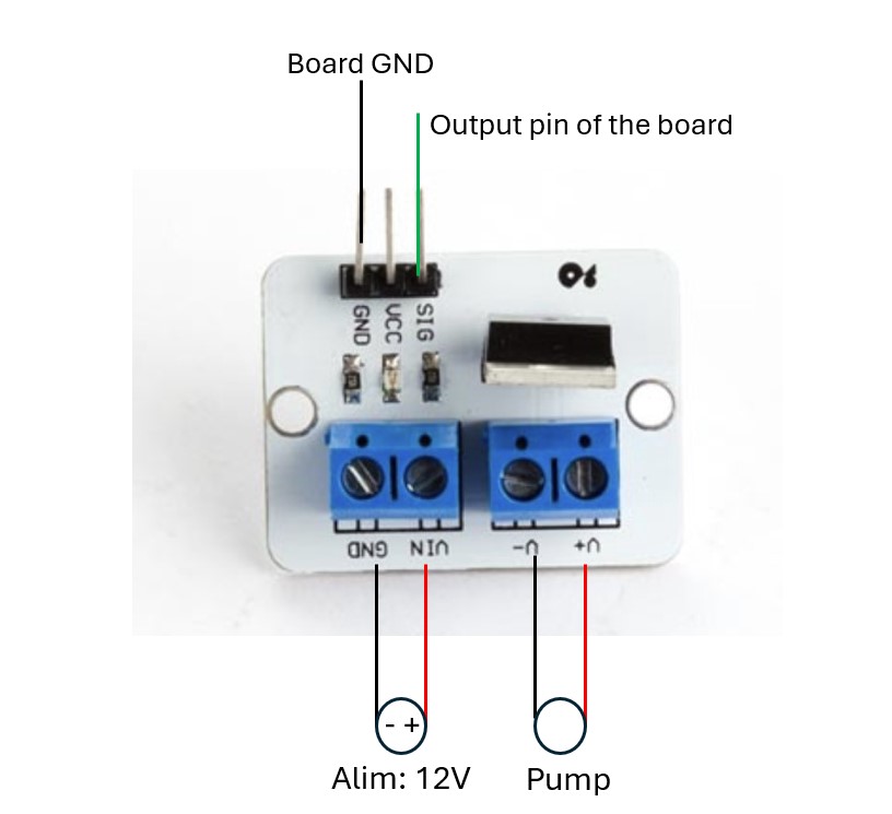
- a MOSFET module based on an IRF520N MOSFET transistor to do the external power and the microcontroller. Indeed, the pump must have a 12V supply, which can not be given directly by the microcontroller.
- a 12V power supply
Connections
Here is how the connections between the microcontroller, the pump and the voltage supply must be done:

Programmation
I used the code did during week 6 to switch on a LED when pressing a button. Here, the output pin is now connected to the pump.
Pressure regulators as output devices
Last week I designed a board that integrates a microcontroller as well as a DAC chip in order to send analog signals ranging from 0 to 10 V to pressure regulators. The analog signal is used to control the pressure output of the pressure regulators. That’s how I will control the pressure in the 3 different channels of my pneumatic actuator for my final project.
This week I will thus use this board to interact with the pressure regulators and try to control the pressure. I will use a manometer to measure the output pressure after the pressure regulator.
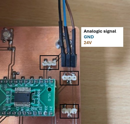
Connections
Switching on the pressure regulators
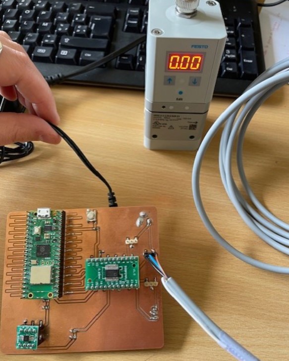
Before trying the communication between the microcontroller and the DAC to send the desired analogic voltage commands to the pressure regulators, I just tested if I was able to switch on the pressure regulators with my board. I connected the pressure regulators on the board and I connected the 24V DC supplier with the jack -> it works, the pressure regulator is working!
Programmation - sending analogic commands to the pressure regulators
During week 6, I started to identify how to communicate with SPI between the microcontroller and the DAC, and I wrote a code that I tested this week.
Issues:
The library that I found on week 6 for the communication between microcontroller and DAC is not working for a Raspberry Pico Pi W board because it was designed for an Arduino board.
Solution:
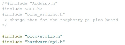
As the functions coded in the library to send the desired output voltage will stay the same even with a different board, I tried to adapt the library designed for the arduino board for my board, by replacing some parts of the code. The main changes are to replace Arduino-specific libraries and functions with their equivalents for the Raspberry Pi Pico.
Here for exemple, I changed libraries that were arduino specific for the corresponding ones for my board
Here are the other big changes in the code, where I change the arduino functions:
Initial code
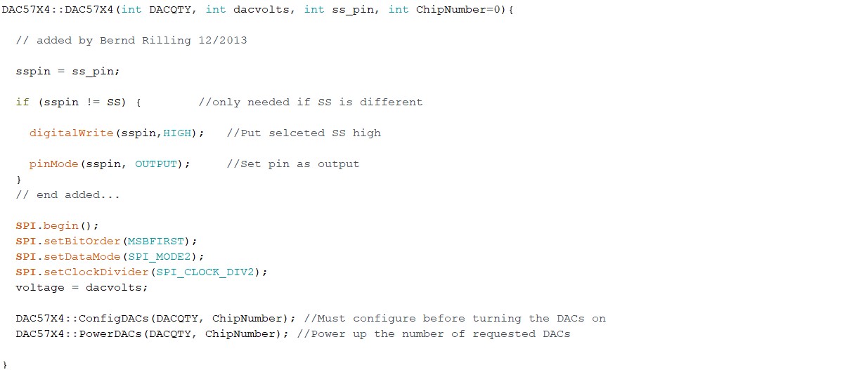
After modification

Testing the code
After the modification of the libraries, I used the code below to set the output voltage of the DAC to 4.0V with the function ‘setDAC()’.
#include "DAC57X4.h" // DAC library
#include "hardware/spi.h"

// setup the DAC : DAC(NumberOfOutputs,VoltageSelection,TheSSPin, ThePhysicalChipNumber)
/*Voltage selections are:

          1 = 0-5V
          2 = 0-10V
          3 = 0-10.8V
          4 = -5-5V
          5 = -10-10V
          6 = -10.8-10.8V
*/

DAC57X4 DAC(1,2,17,0);

void setup() {
  Serial.begin(9600);
}

void loop() {
 DAC.SetDAC(4.0,1,0);
}
It’s working! You can see on the video that the command signal pass from 4.1V to 4.0V when I send the command.
Now the last step is to connect my pressure regulator to a air compressor and to do a mapping table between the voltage command (here 4.0V) and the output pressure, so I can use this for the control of my pneumatic actuator for my final project.
Source files
The code source files, i.e. the libraries for SPI communication between RP2040 and DAC, and the code to send control signals can be downloaded here
Note
I didn’t included that pump in my final project.