Week 3: Computer Controlled cutting
Assignments of the week
This week there were two assignements, one to do by group with the other students of our FabLab and one alone.
Group assignement: characterize your lasercutter’s focus, power, speed, rate, kerf, joint clearance and types.
The group assignment results can be found on our fablab page.
Personnal assignement:
- cut something on the vinylcutter
- design, lasercut, and document a parametric construction kit, accounting for the lasercutter kerf, which can be assembled in multiple ways, and for extra credit include elements that aren’t flat
Vinyl cutter
The vinyl cutter of my Fablab is a Silhouette Cameo. To use it, you just need to make a vector drawing and send it to the machine, by using the software of the machine - Silhouette Studio.
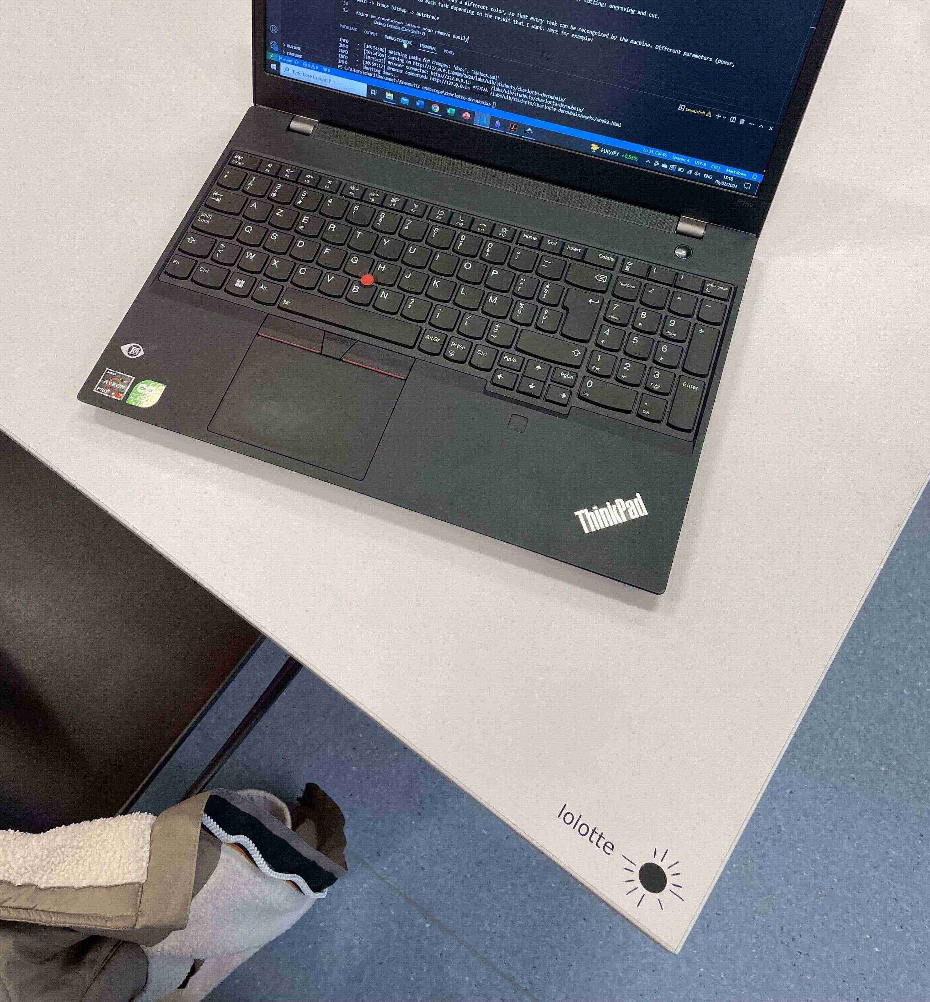
For the vinyl cutter assignment, I just did a very quick design on Inkscape with my nickname and a sun logo found on internet.
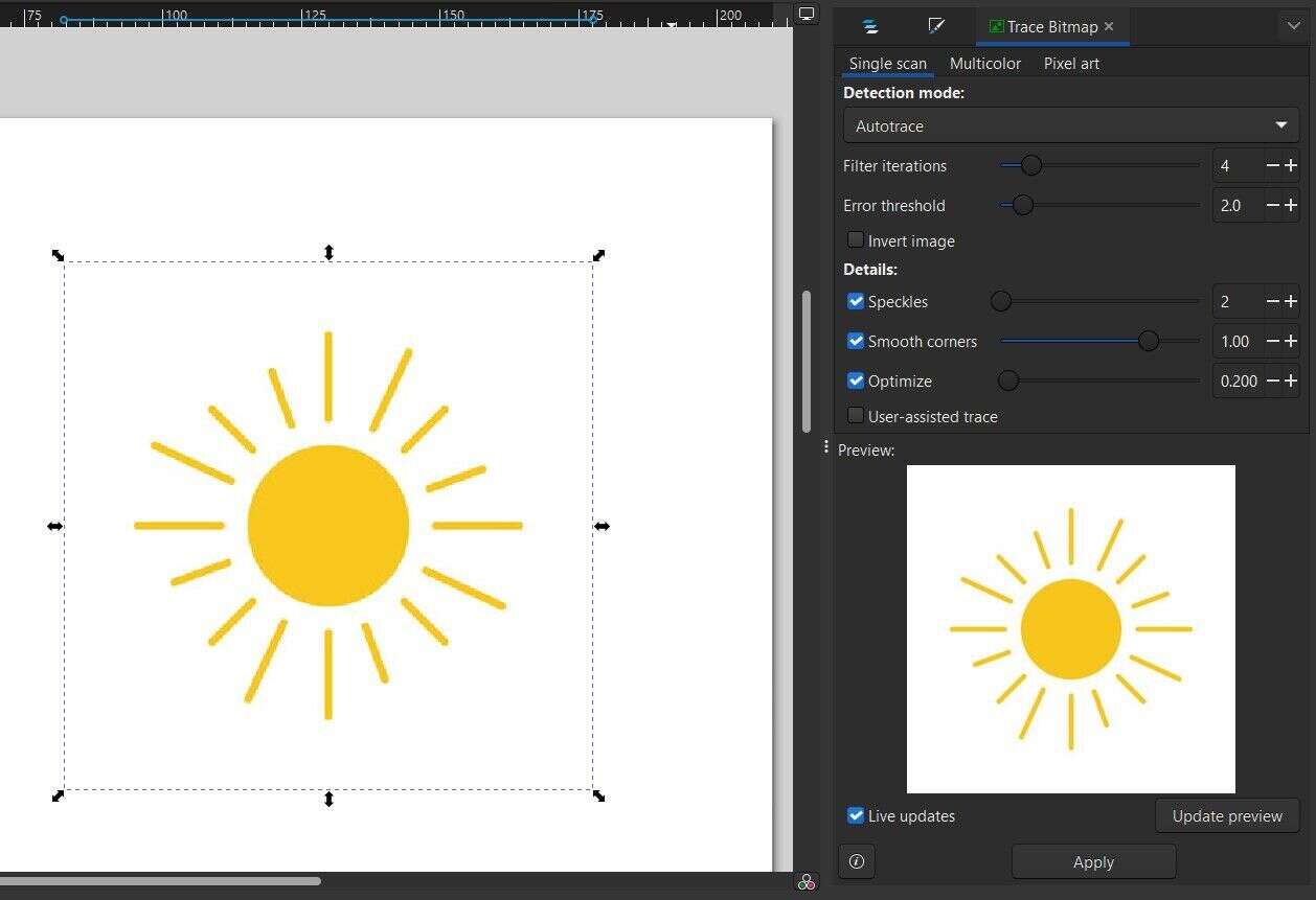
I imported the picture of the sun on Inkscape and I vectorized it to obtain a path in order to be able to trace it with the vinyl cutter (select the image on Inkscape -> path -> trace bitmap -> autotrace). When the design is ready, the file should be saved as a “.dxf” file to be read by the vinyl cutter software.
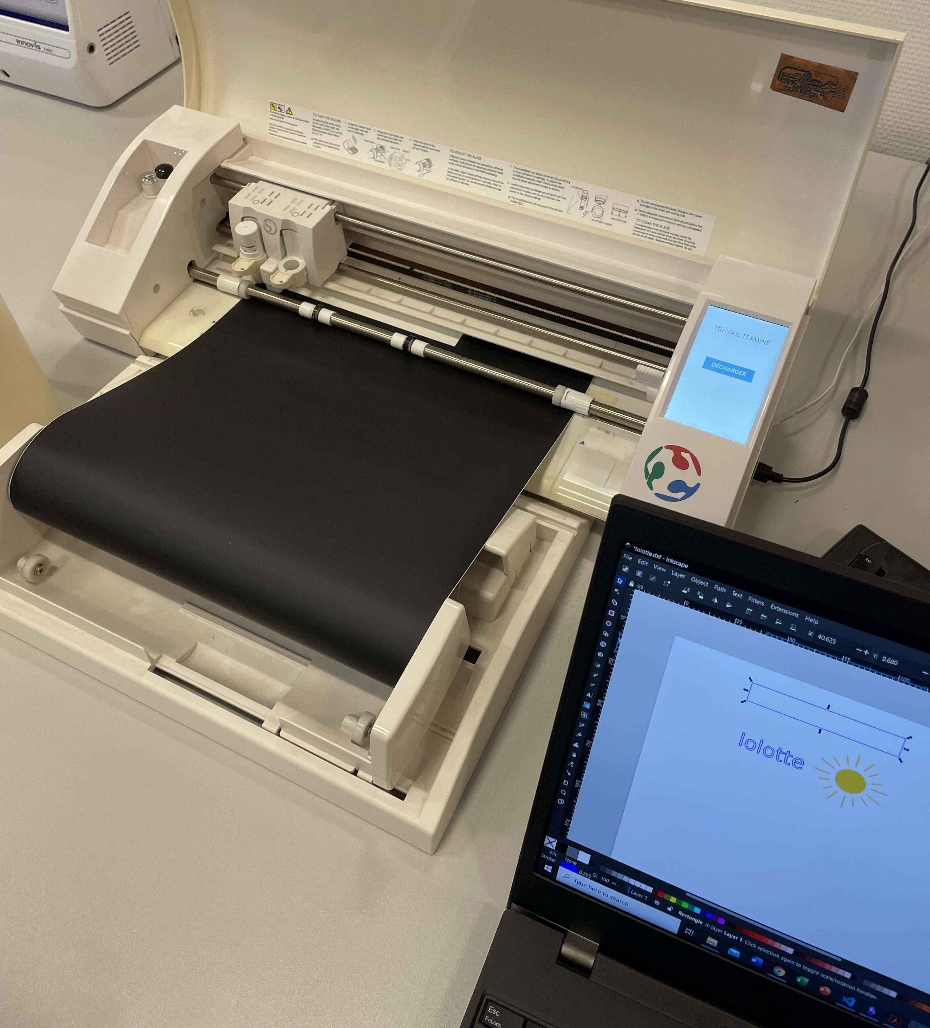
When the “.dxl” file is ready with the design, it is ready to be cut with the vinyl cutter. There is not a lot of parameters to modify on the software to be able to cut the design, and the more important one is the choice of the material. Here I used a black mat vinyl, so I just put “mat vinyl” and then the blade settings will be fixed based on the material. The dxf source file of the design can be downloaded here.
When ready, you just need to load the vinyl material on the machine, as shown below. Then just press “send” on the software and that’s it.
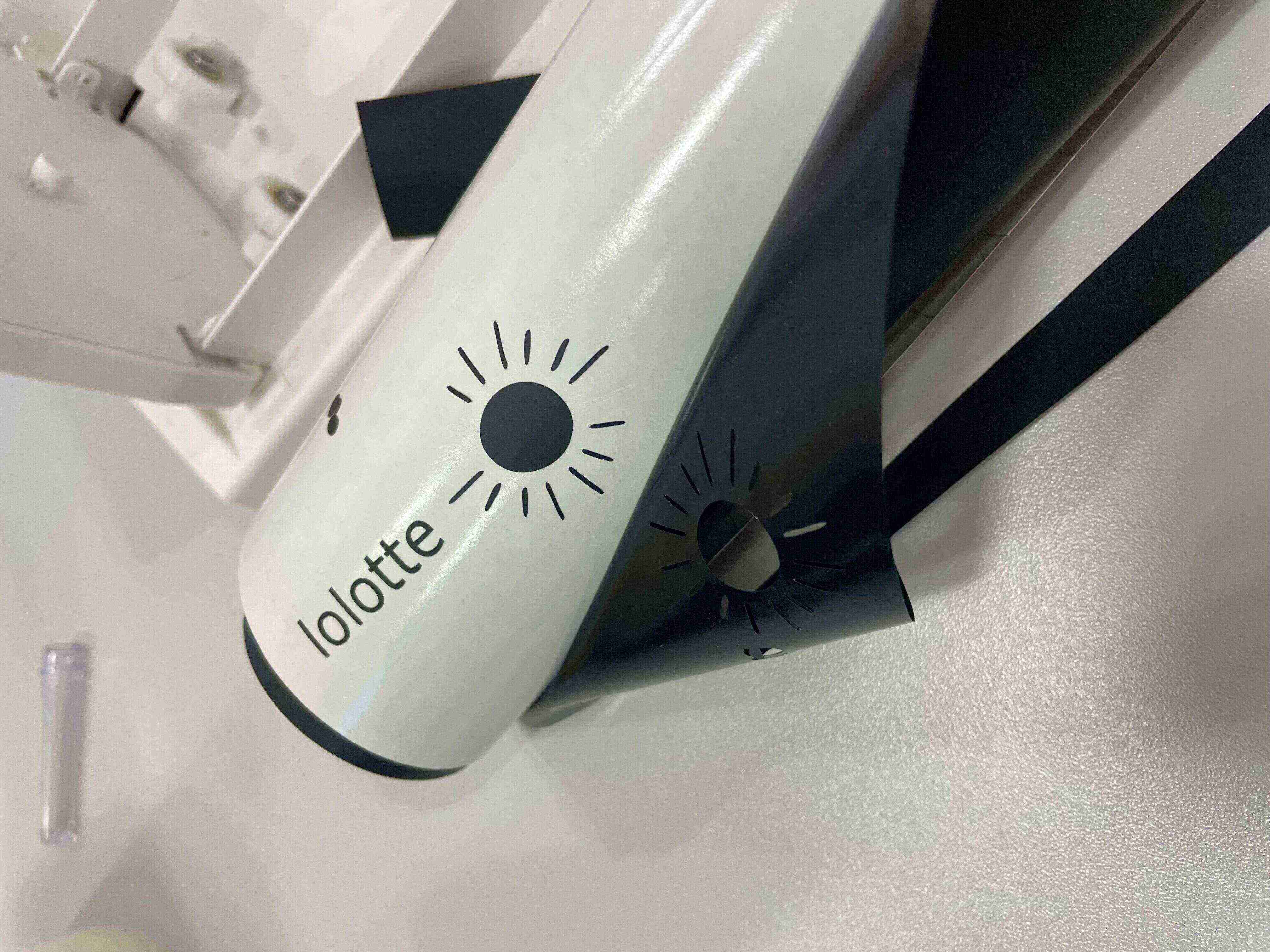
You can use a adhesive rubber to stick it on the cutted vinyl design and then put it wherever you want. Here I putted it on my Fablab’ desk.
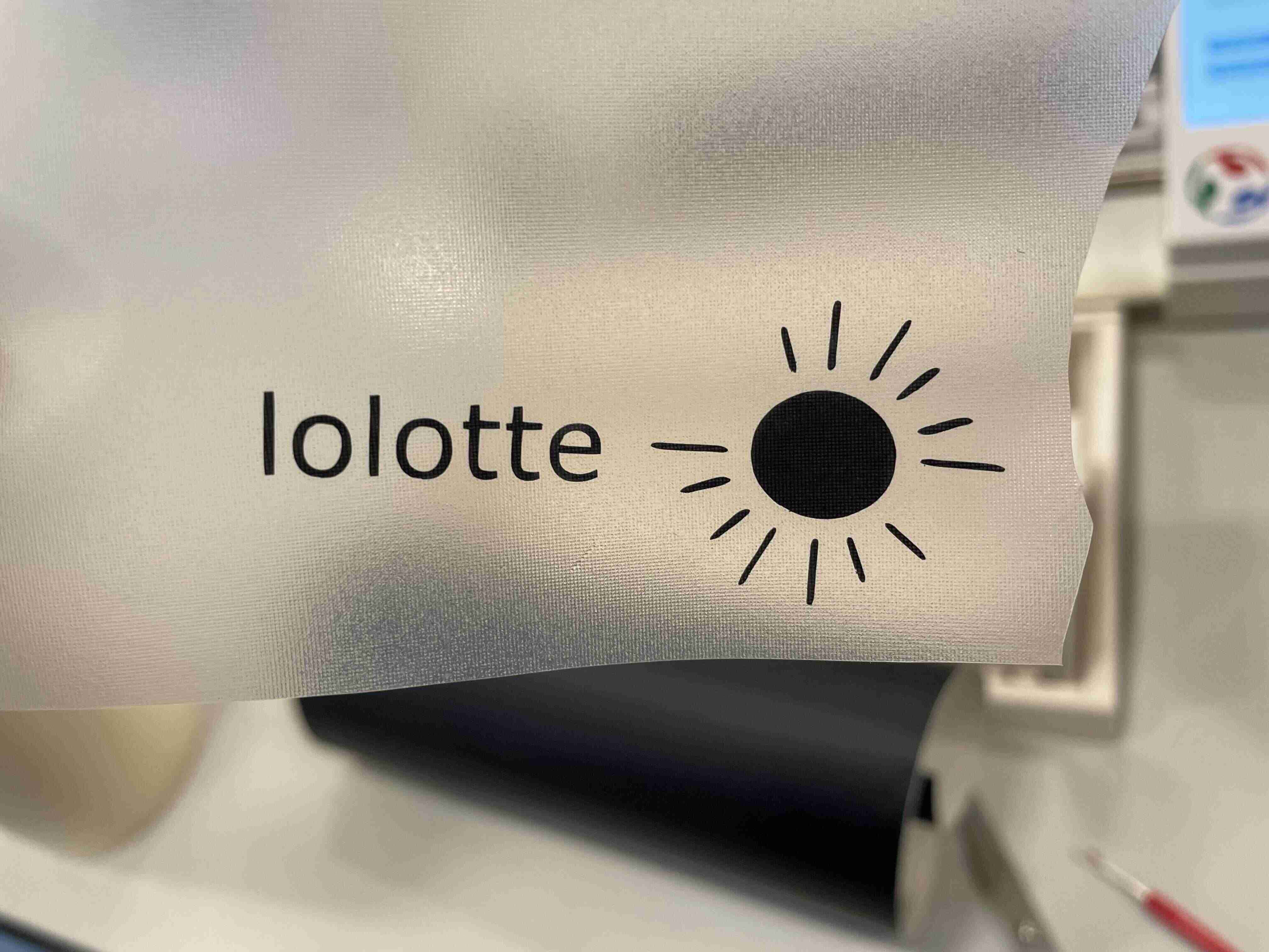
Improvement: to a rectangular countainer around the design so it’s easier to remove it from the vinyl cutter.
First try with the laser cutter
There are two different laser cutter at the ULB fablab:
- A custom Lasersaur that has been assembled in the fablab;
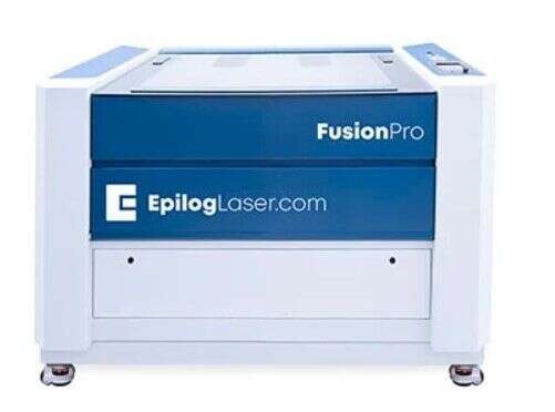
- An industrial machine: Epilog Laser Fusion Pro
My first try was to do a very easy drawing on Inkscape to test the different types of cutting: engraving and cut. Each part of the drawing should be defined as a “path” in Inkscape, so that the machine can follow it. To be sure that each object is a path: select everything -> path -> object to path. When the drawing is ready, it should be saved as a “.SVG” file.
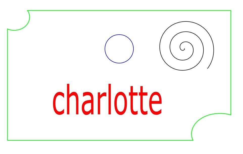
We can see that each different task has a different color, so that every task can be recongnized by the machine. Different parameters (power, speed) will be assigned to each task depending on the result that I want or to determine the order of the task. Here for example:
- red: surface engraving -> first task to be executed
- black: engraving -> second task
- blue: cut -> third task
- green: cut -> last task
The task order is important to be sure that every task is done properly. For exemple, if we begin by cutting the green part, it’s possible that the piece will detach from the cardboard and will move a bit, so the other task won’t be precise. The task will be placed in the same order on the machine program.
Results of the first try
To obtain a good cut or engraving, the speed and power parameter of the laser must be fixed for each task depending on the result that we want. Here, a characterization of the laser cutter on the cardboard that I wanted to use had already been done, as shown on the picture below.
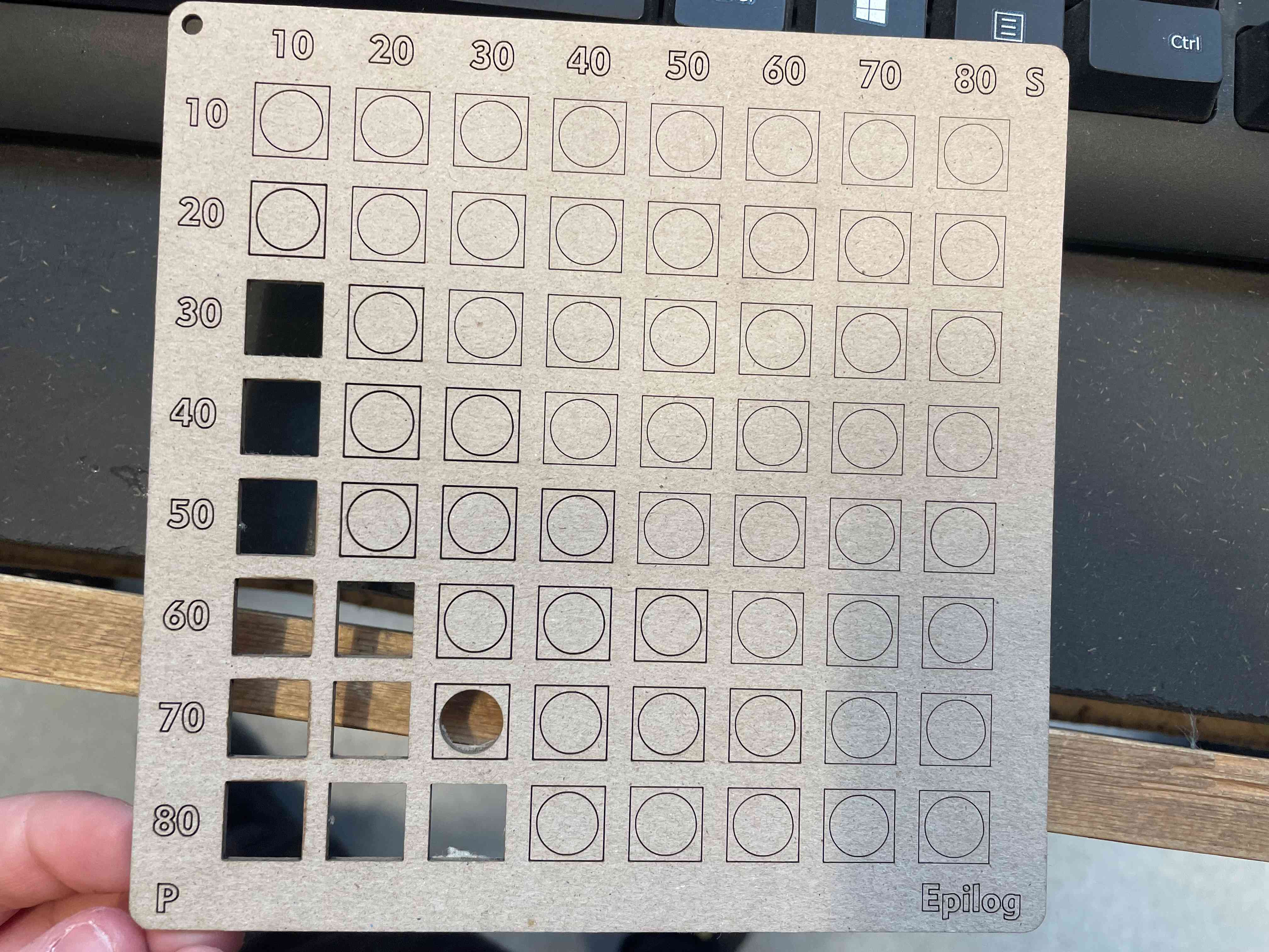
Unfortunately, the parameter that I chose for the cutting tasks (blue and green) were not good enough, the laser didn’t cut through the whole tickness of the cardboard. It could be caused by the thickness of the cardboard that was not exactly the same has the one used for the characterization.
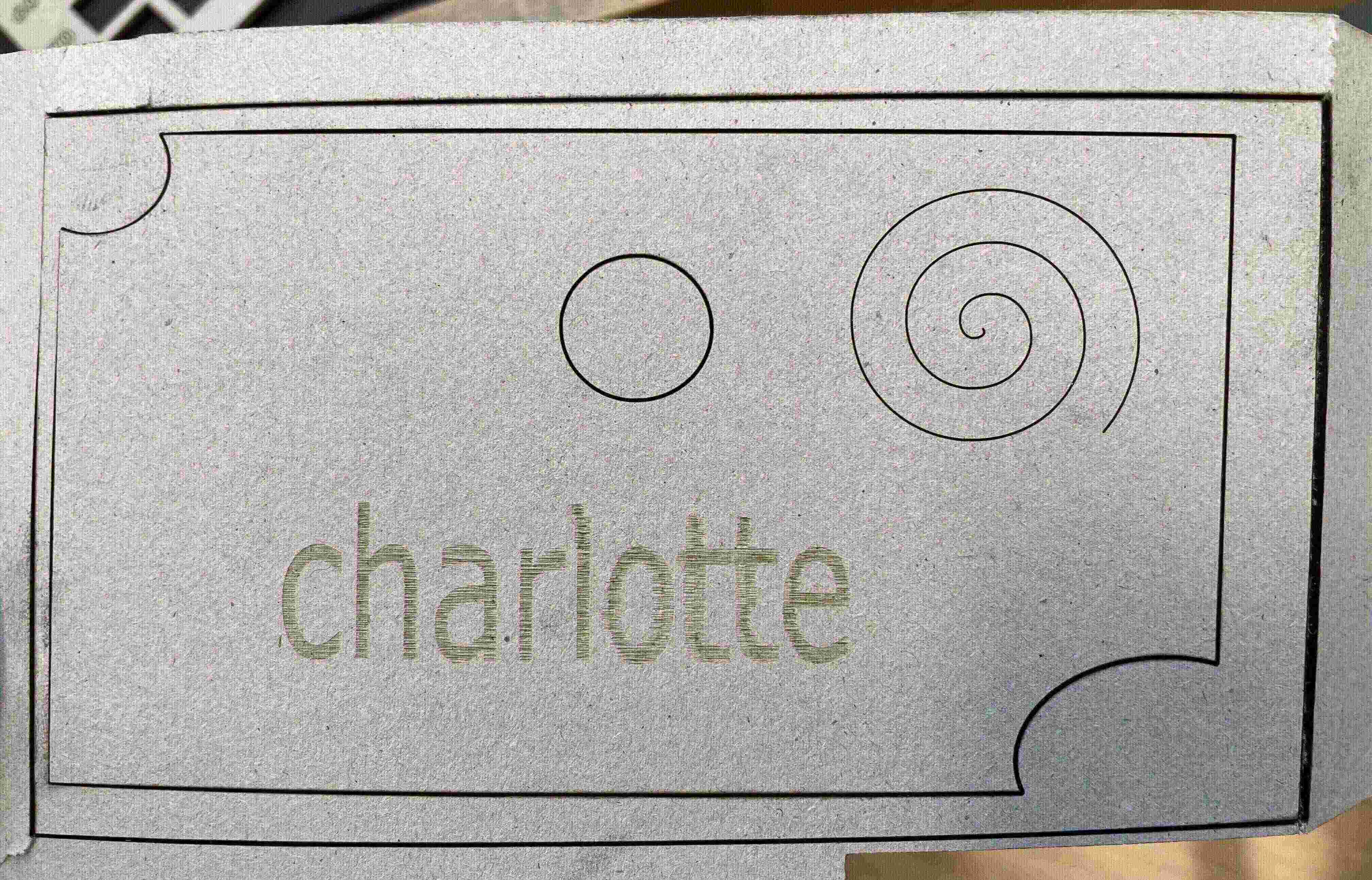
Improvement: the cut can be improved either by reducing the speed used or by increasing the power.
Parametric kit
For the assignment of the week I chose a basic parametric kit that was already done is a past project of the Fab Academy (link), but that I have adapted in terms of dimensions in order to be able to integrate it in my test bench for my final project. The goal will be to use this kit to create a camera holder system, that will be linked to an articulated arm (done with the laser cutter as well). The parts could also be assembled in different ways to create other objects.
Parametric parts design
To design the parametric parts, I used FreeCAD that I started using in week 2.
I have created a spreadsheet and defined all the different dimensions that are linked to each other, so if I decide to change one, the other one will be updated as well. I want to use my parametric parts to hold some cameras, so the size of my parts have been chosen considering some fixed parameters which correspond to the dimensions of the camera.
The parametrisation is also very important for the press fit, because to have a good press fit, the slots should be well dimensioned. To do so, i have created a parameter “fit” in my spreadsheet, that is used to adjust the size of the slot. I have used the characterization done during the group assignement to determine it.

Here you can see the different parts that have been designed.
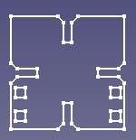
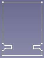


The parametric kit source files can be downloaded here.
I have also exported my parts on Solidworks to create an assembly and to verify that I didn’t make any mistake in the parts design, to be sure that everything was fitting well. It’s probably possible to create an assembly directly in FreeCAD but I didn’t have so much time so I went for the quickest option.
- In FreeCAD export the sketch as a “.dxf” file
- Open it with Solidworks -> Import to a new part - 2D sketch
- Choose the good units (millimeter here)-> check “import dimensions”
- The sketch is imported -> it can be extruded
- Put everything together in an assembly
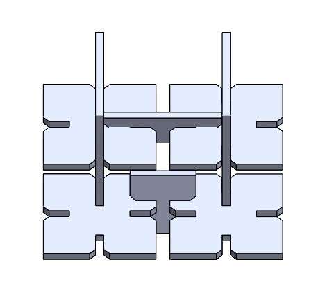
When the sketch are done, you can prepare the file to send to the laser cutter. To do that I used Inkscape:
- Export the sketch as a “.dxf” file
- Open the file with Inkscape
- The sketch is recognized as multiple objects: select all the objects -> object -> group
- To multiply the parts: Edit -> clone -> create tilted clones / or just copy/past the parts
- Be sure that everything is a vector/path: Select all -> path -> object to path
- Save the file in SVG
- Let’s cut
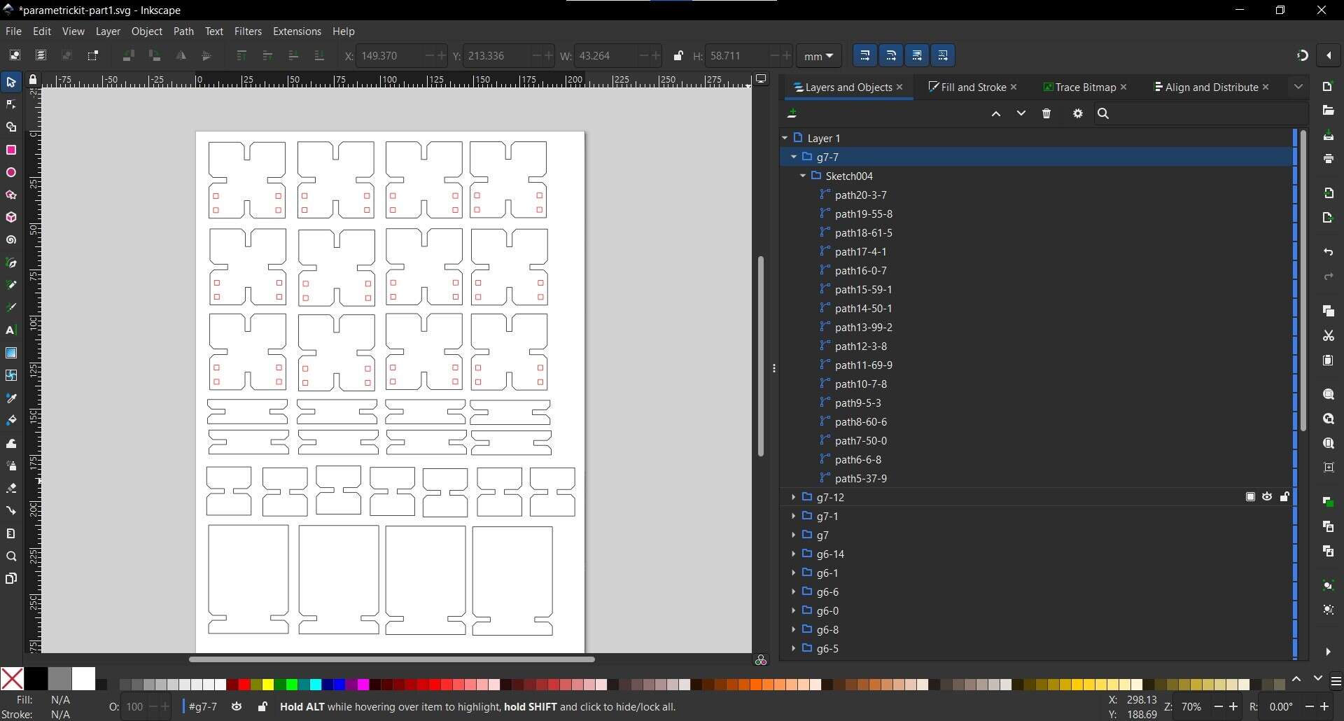
As we can see above, I have put 2 colors so the path in red are cut first and then the black ones. I have used cardboard to cut my pieces, and I have used the characterization that we did during the group assignement to choose my parameters in order to cut the cardboard completely but without burning it and not to slowly:
- speed: 1380mm/min
- power: 60%
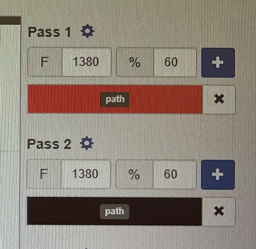
Parameters in the lasersaur software with each color assign to each task
I used the second laser cutter of my fablab, the homemade “Lasersaur”, and I used the tutorial described on the gitlab of the fablab.

Results
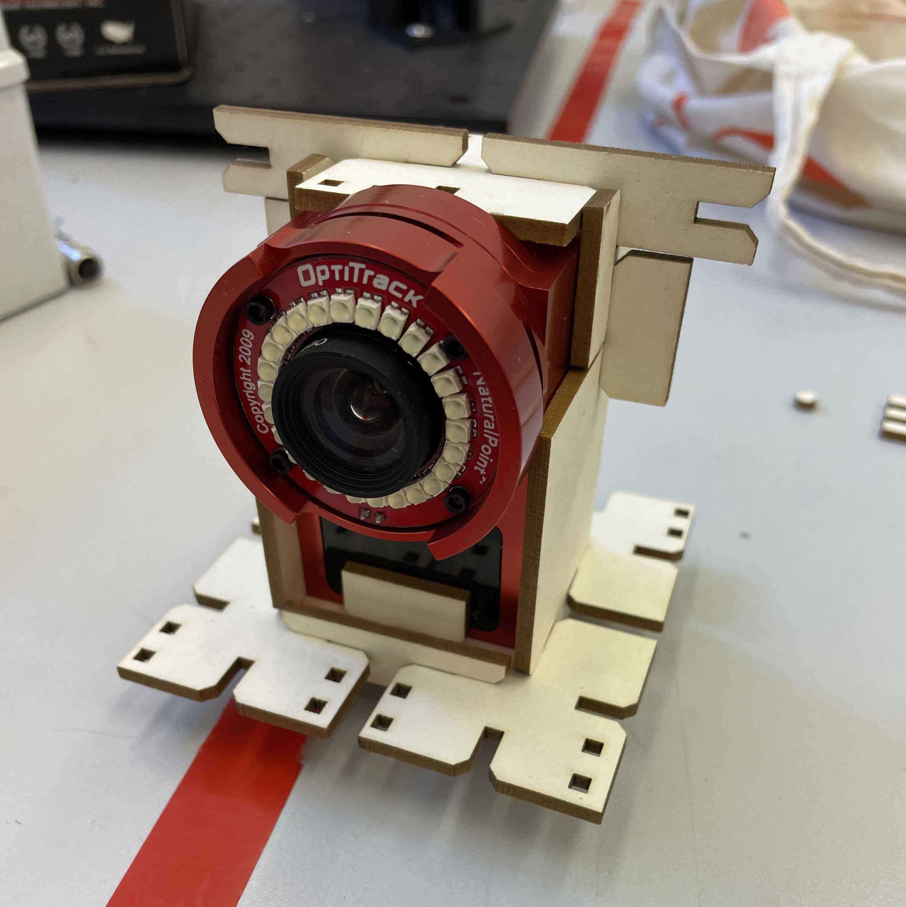
Everything fits well! The fit is very tight so there is very few movement between the parts, which is great so the camera will be well fixed on it. We can see on the picture below that the cardboard is not burn either.
Articulated arm for camera
I have also design other parts to link the camera and its support developped above, with an articulated arm in order to be able to incline the camera. The inspiration of the articulated arm is from this tutorial, and the principle is similar to every arm camera that can be found in the commerce.
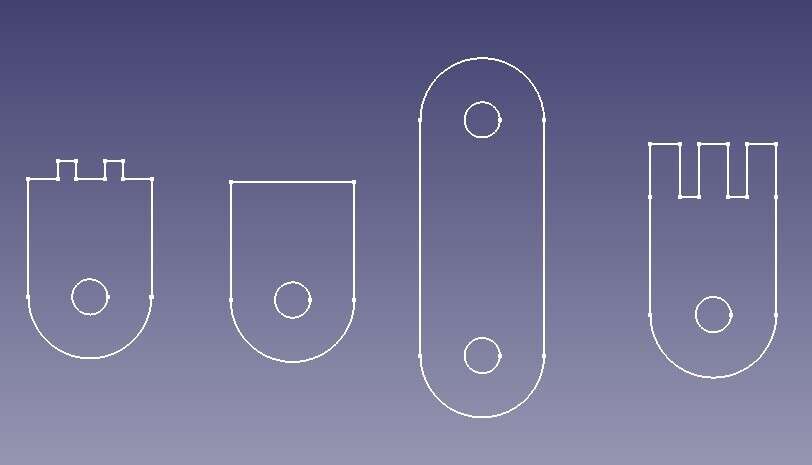
I followed the same steps to cut my pieces.
Results
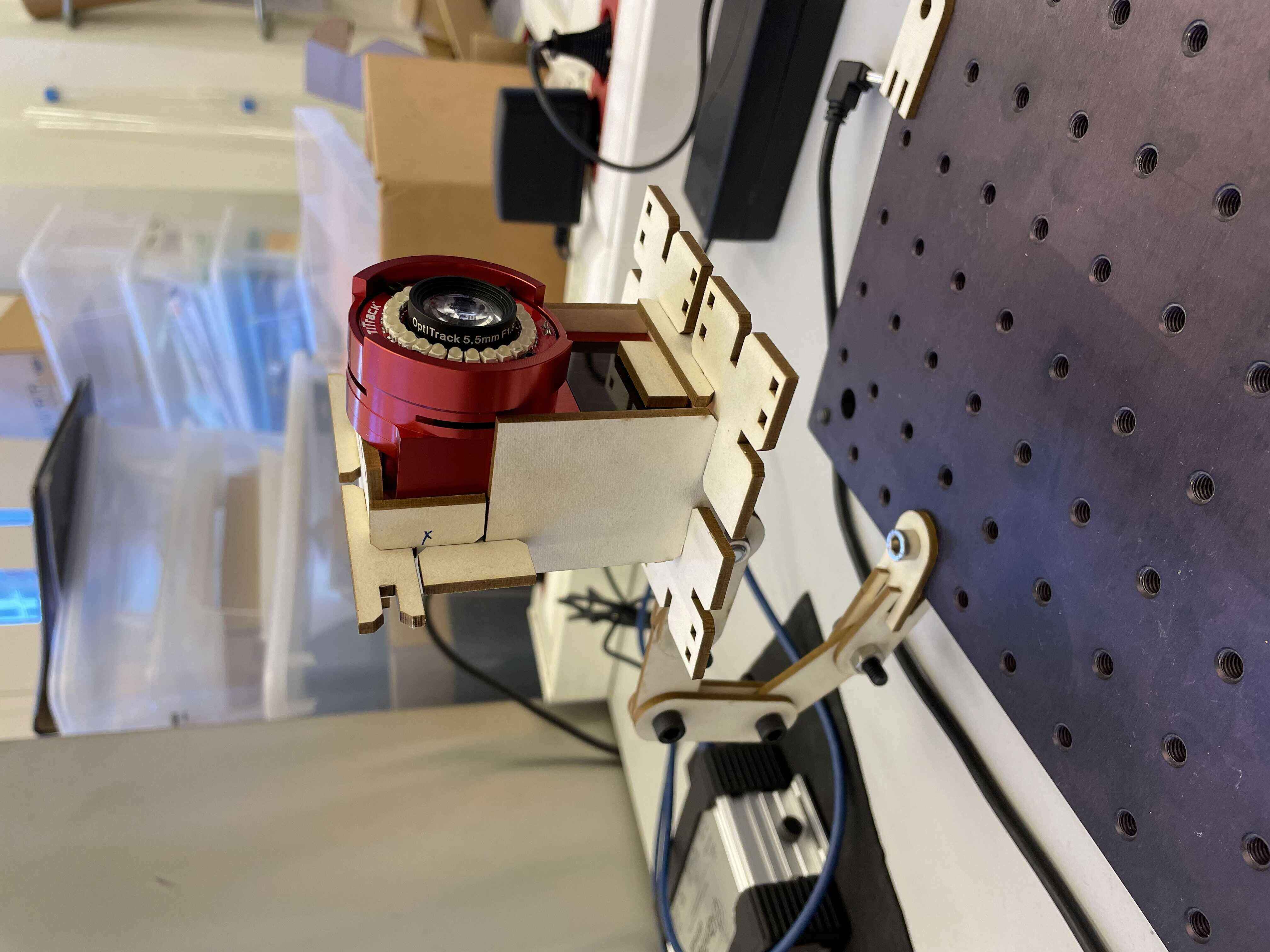
The result is quite good and satisfying!
Improvements
There is some improvements that could be made:
- I used cardboard for the articulated arm, but wood could be better, espacially for the pieces that fix the arm on the test bench, which are a bit deform due to the load on it.
- After a 45° angle of inclination of the camera, it becomes a bit unstable on the support, which could cause some artefacts during the recording of the tracker movements. I need to fix the camera better if I want to use larger inclination angles.
Update week 11
I cut the parts again, but using wood rather than cardboard to obtain a more rigid structure without deformation, as suggested above after testing in week 3.
Update week 13
For my final project I used the laser cutter again to cut out the layer jamming structure.
The idea of the layer jamming structure is to have 3 bands of the same length as my pneumatic actuator, wrapped around it.