Test bench
The test bench developped in this final project will be used to characterize bending and force properties of a pneumatic silicone actuator.
Pressure control
The first important part of my test bench is the pressure control: my pneumatic actuator embed 3 pneumatic chambers, that can be pressurized to obtain a bending. Depending on the pressure applied in each chamber, the actuator is bent with a certain angle and orientation. It’s thus an important factor to control precisely, and also independently in each chamber.

Pressure regulators
To be able to control the pressure precisely, I opted for an already made industrial pressure regulator option from FESTO - the VPPE Proportional pressure control valve . I could have developped a electronic pressure regulator by myself during the Fab Academy, but it would have lead to less time for the prototyping of my pneumatic actuator, which is the main concern of my thesis right now, so it was more important for me to focus on that.

I made the choice based on my pressure actuation requirements:
- The pressure in the chamber will be between 0.05 bar up to 4 bar -> the VPPE pressure regulation range is from 0.06 bar up to 6 bar.
- The inlet pressure of the VPPE is from 6 to 8 bar, corresponding to the compressor available at my lab.
Week 8: board for the control of the pressure regulator
To achieve the desired pressure, analog control signals are sent to the pressure regulators. These analog control signals range from 0 to 10V. Some predefind pressure can also be saved on the regulators, but it’s good to have the possibility to send command to them with my computer. During the electronics design week, I thus designed a board that allows me to send these analog control signals to the pressure regulators. The details of the PCB design process are developped in the weekly assignment page, as well as the details of the components of the board, but you can see here the final board PCB design, and the result after the soldering. The board includes a RP2040 microcontroller and a DAC (digital to analog converter), that communicate together with SPI communication ( see week6 and week 14 for SPI communication details). The idea is to control the DAC via SPI communication with the microcontroller, in order to have 3 independant analogic outputs ranging from 0 to 10V, that will control the pressure regulators. The board also includes a voltage reference chip for the DAC.


Week 12: Pressure sensor
I don’t need pressure sensor for the control of the pressure as there is a pressure sensor included in the pressure regulators that I use. However, I would like to have an interface that display the pressure inside the pneumatic chambers in real time, to directly have a better idea of what pressures are used for each bending.
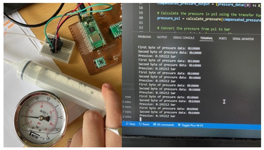
During week 12: input device week I thus tested a I2C pressure sensor and printed the values of the applied pressure in a terminal. Next step is to display them on an interface -> see later.
Week 14: Code for the control of the pressure regulator
During the week of communication, I did a code to control my pressure regulator. The code establish a communication via SPI between the microcontroller and the DAC, in order to obtain the desired output voltages. These outputs are then used for the control of the pressure regulator, because each analogic output ranging from 0 to 10V correspond to a pressure.
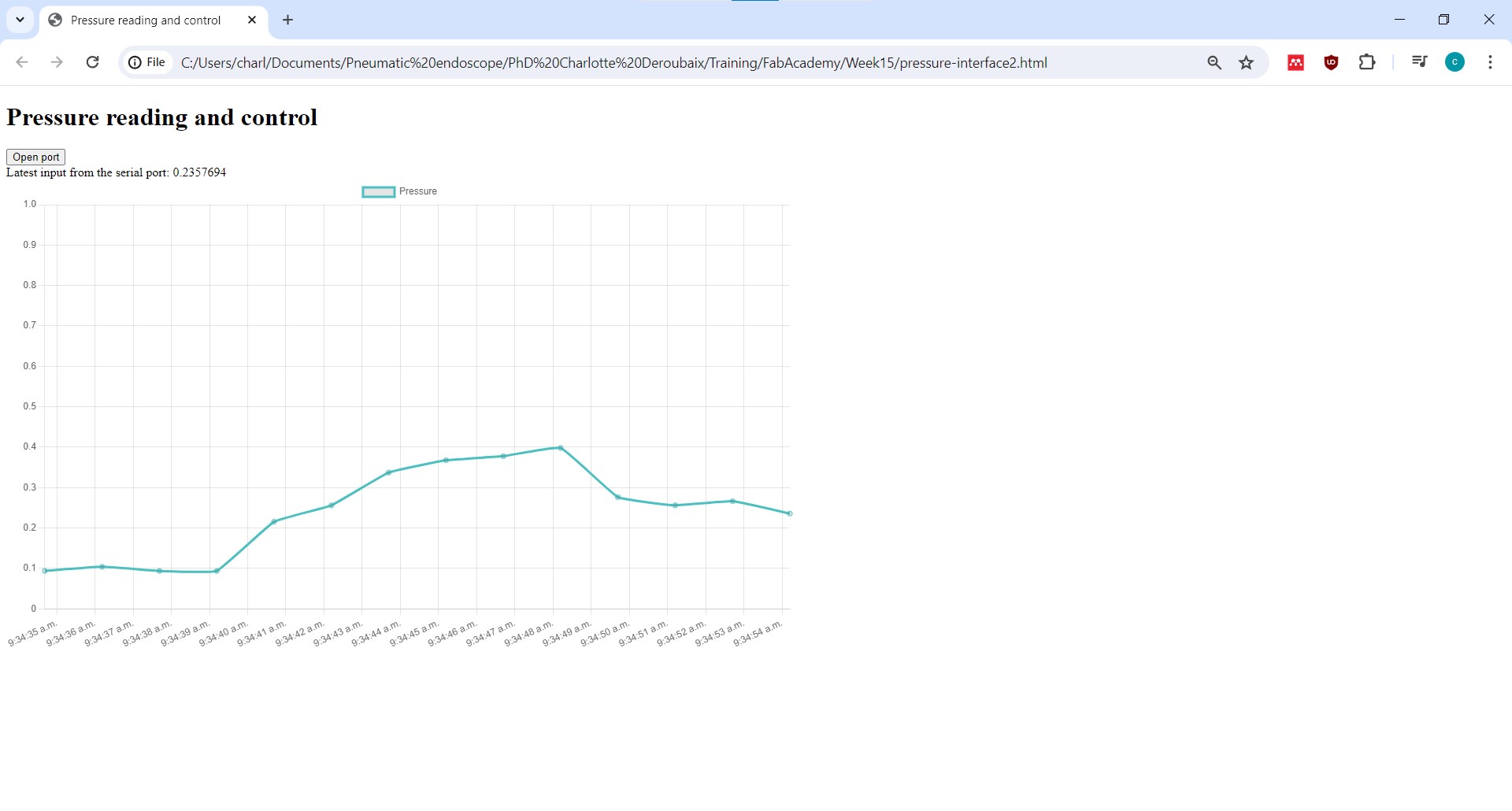
Week 15: Interface for pressure display
As explained a bit above, I want to display the pressure inside the pneumatic chamber of my penumatic actuator, to know which pressure is needed for a certain bending angle. During week 15, I thus did this interface. It’s a web browser user interface so it can be used on almost every computer without any need of downloading specific softwares or libraries. The web browser interface use the “web serial API” to allow the communication between the browser and the microcontroller directly via USB serial port.
Mechanical structure
Week 2: Design of the mechanical parts
During week 2 I already started to think about every needed parts for my final project, and I designed them. You can go and check to see every parts needed. I then 3D printed some of the parts using a Prusa printer, and the rest of the structure parts were gathered in my fablab (it was unused).
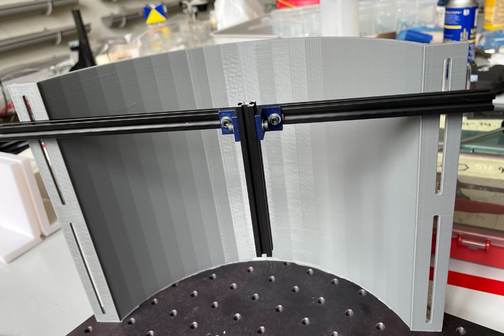
On the picture below you can see the aluminium extrusion that were gathered at my fablab fixed with the pieces designed in week 2 on the background that also designed in week 2.
Week 3: Design and making of a camera arm
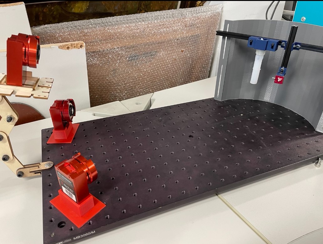
I needed some camera holder able to fix the camera in the test bench but also to incline the camera easily. During week 3 I created a camera holder arm, and I cut its parts using a laser cutter.

I also designed a 3D printed camera holder that is just place on the test bench, to have camera at different height in the set up. Here is a picture of the printed result:

Week 17: Integration system
The integration system week was really usefull to integrate all the different parts of my project together. Indeed, I tested a bit everything separately but it was a good time to link everything together and also to make things look clean and organized as I have a lot of cables.
As i t can be seen on the picture below, I havfe a lot of cables to deal with due to the camera, pressure regulators and also the pneumatic tubes.
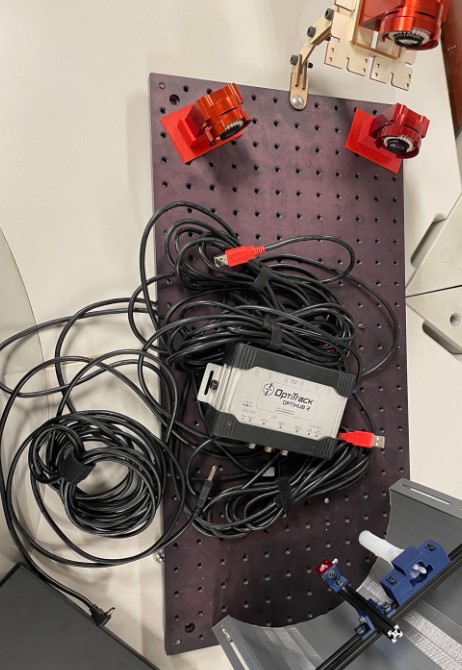
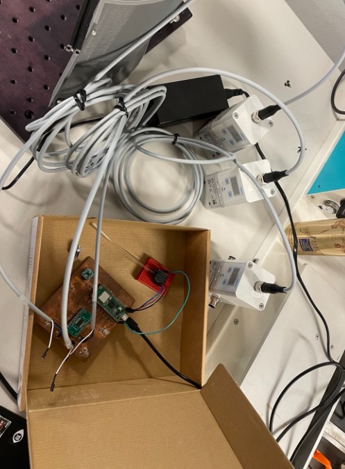
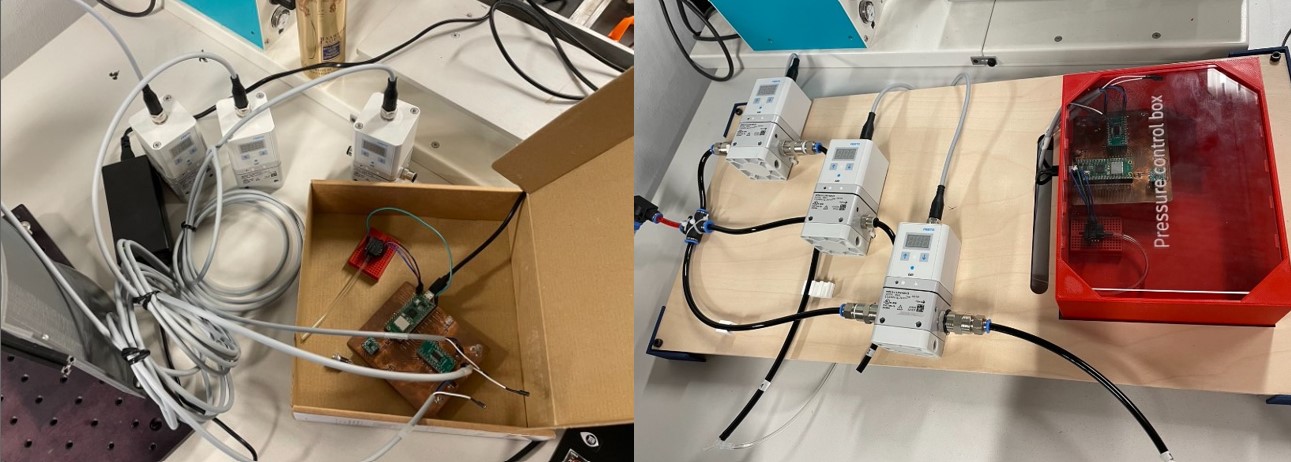
During this week I did an integration system board to link the pressure regulators to the electronic board that control them. You can see here a before and after of the organization.
Week 17: Assembling the test bench
I also used this week to assemble my test bench. The picture below shows the final result but you can go and look at the details of assembly in the week 17.
Validation test bench
Week 18: Testing everything together
I did multiple tests to validate my test bench:
1) I tested the multi directionnal control
I wrote some control functions and I integratd it in my code. The functions dictate how the voltage command, and thus the pressure, will change depending on what I want to do. For example, the function below increases the voltage command that is sent to the pressure regulator step by step, so the pressure applied in the air chamber is slightly increase step by step as well. Here, one canal will be actuated, than the second one, than the third.
def vary_voltage():
    for i in range(0, 19, 1):
        voltage = 4.6 + i*0.2
        voltage2= voltage+0.2
        set_voltage(0b000, voltage) #send command for the pressure regulator 1
        time.sleep(1)
    for i in range(0, 19, 1):
        voltage2 = 4.6 + i*0.2
        set_voltage(0b001,voltage2) #send command for the pressure regulator 2
        time.sleep(1)
    for i in range(0, 19, 1):
        voltage3 = 4.6 + i*0.2
        set_voltage(0b010,voltage2) #send command for the pressure regulator 3
        time.sleep(1)
Here is the result (2.5 times faster). It’s working well and as expected!
2) I tested the camera tracking system
All the details concerning the tracking are explained on this following page: tracking The details concern how the tracking works, how to calibrate the camera to track the markers correctly, how to start recording a file, how to export the file and process the data to obtain the bending angle.
Here you can see a video of the software that i’m using for the tracking. I’m using 3 cameras, so you can see the 3 cameras vision and the markers that are moving on each camera window.