Week 17: System integration
Assisgnment
Design and document the system integration for your final project
What I did
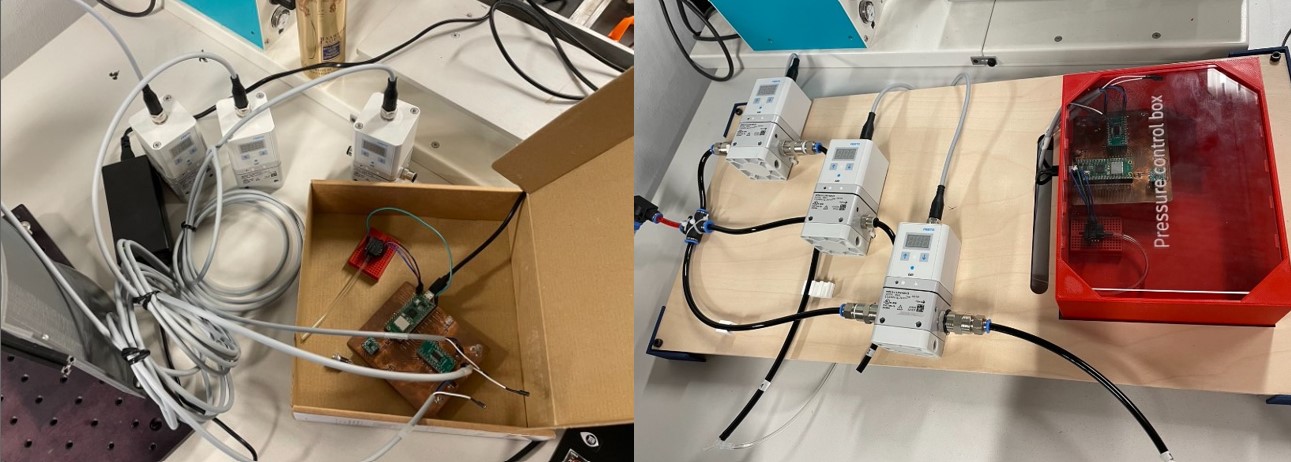
Here is a before/after of the pressure regulators and the electronic that I use for my final project.
To do for the integration system
Ok so obvioulsy this week will be focus only on the final project. I have already every parts of my final project that works separetly but this week is the perfect week to assemble everything and make it looks good. I have a lot of cables for the different camera, microcontroller, pressure regulator, and also some pneumatic tubes, so I will do a big job to hide/organize everything.
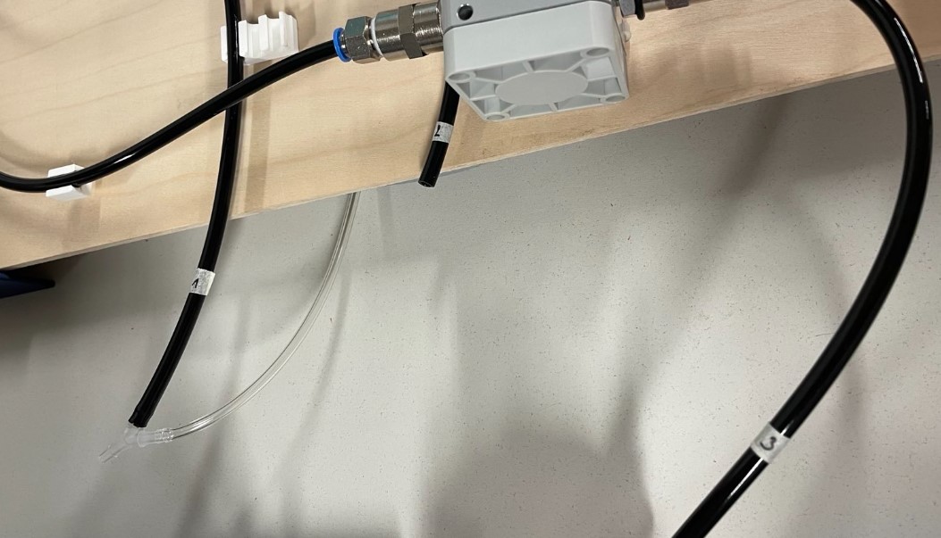
Before the integration system
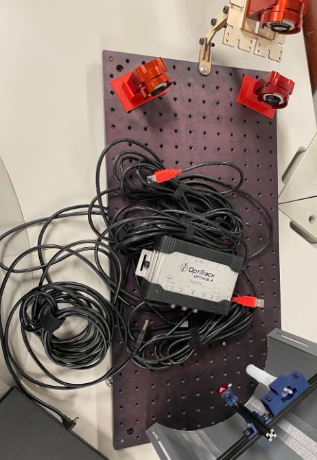
Here is the type of cables I am talking about: I need all of this cable just for the cameras.
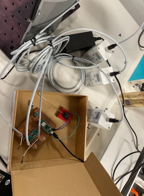
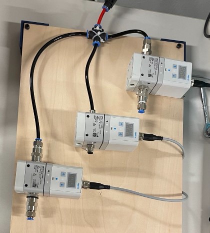
I also have 3 pressure regulators, so 3 other cables. They must be connected to my board, as shown on the picture below. There will also be 6 pneumatic tubes (3 going in the regulator and 3 going out). For the moment the board is in a cardboard box, so I need to do something about it also.
To do
- An box for the electronic
- A board to hide/organize the cables and the pressure regulators.
Electronic box
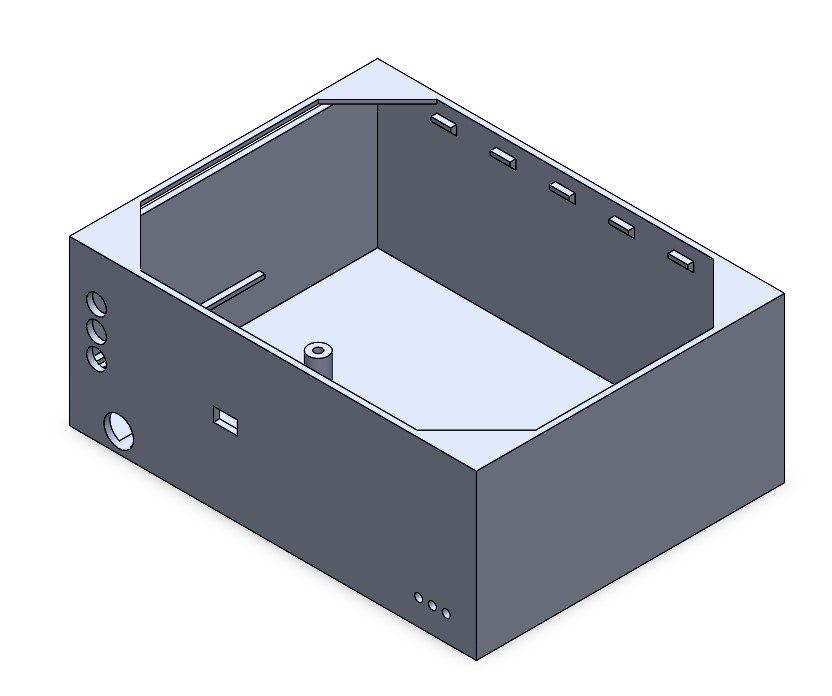
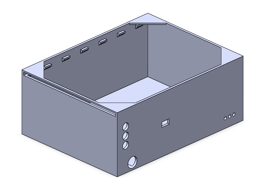
The electronic box will integer the control board of the pressure regulator, as well as the pressure sensors. I have thus designed the box to have enough room for these components. I also think about how to place the component inside the box to be as praticle as possible.
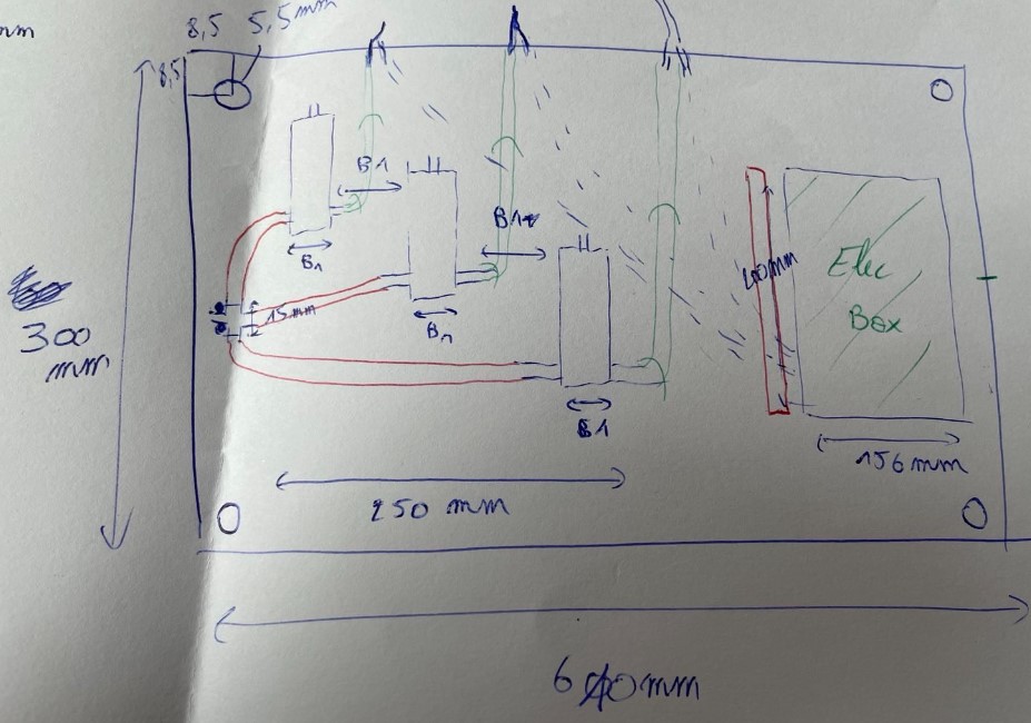
I have made a small drawing of the design before design the box on Solidworks to be sure to not forget anything.
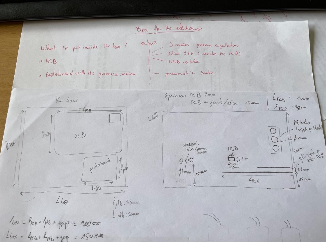
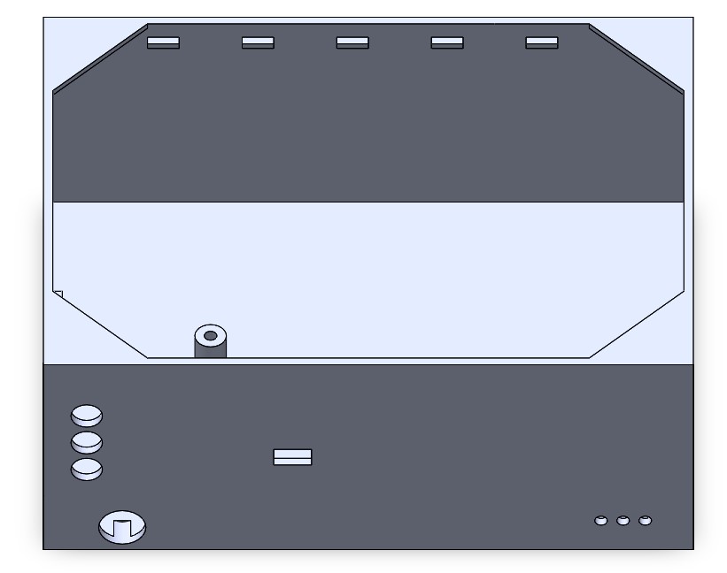
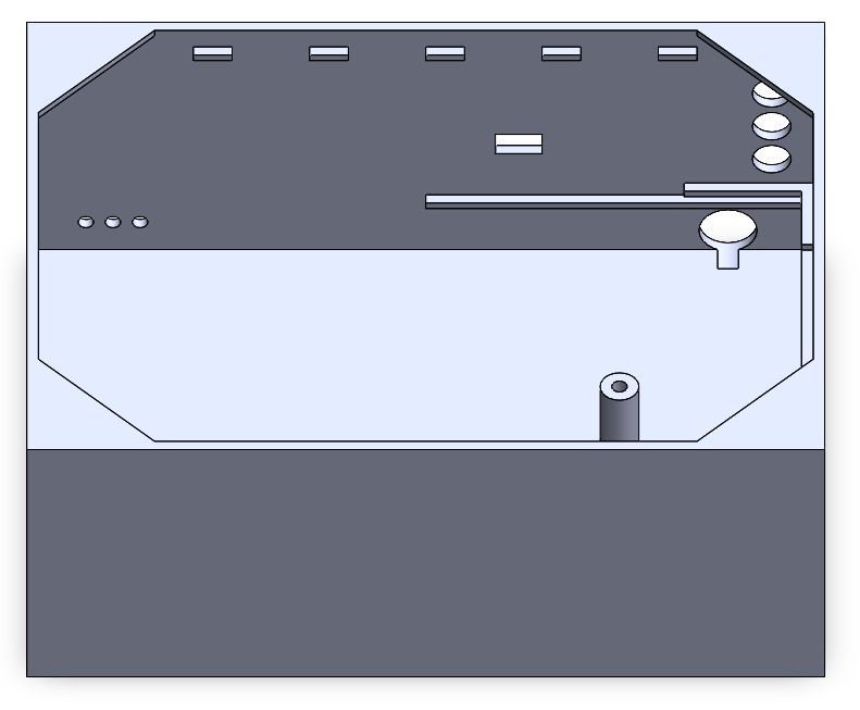
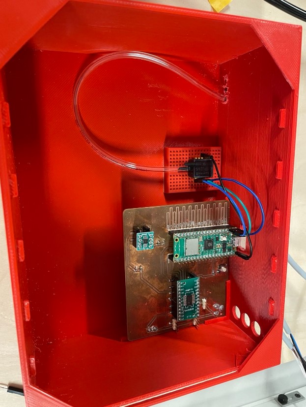
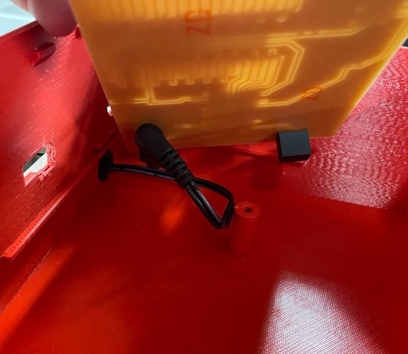
The board will be raised up from the bottom of the box because there is a connector under my board. I add a hole next to the connector to have access to it. To raise up the board, I used two rails between which the board will be slide. There is also a cylinder that will stabilize the board and allow to put a screw in it, to fix the board completely.

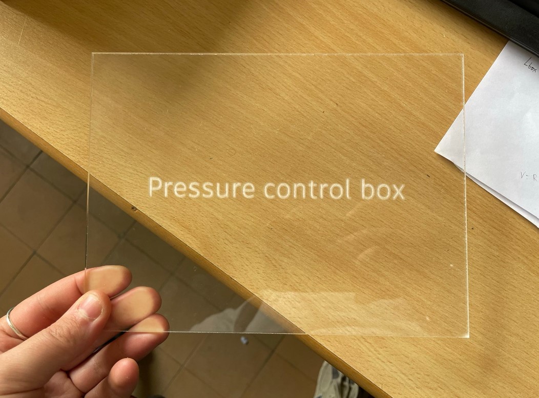
Nothing special to say about the box design, there are multiple holes in the wall to allow the cables and pneumatic tubes to go out of the box. I then closed the box with a plexiglas removable cover. It allows to see indside the box and the slider allow to have an easy access if needed.
Making
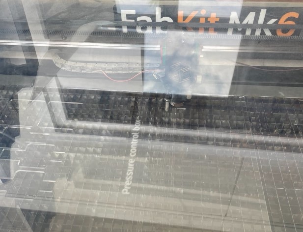
I 3D printed the box with a Prusa printer and I used a laser cutter to cut a plexiglass cover. I did the design of the cover directly in Inkscape.
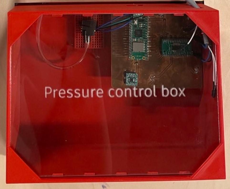
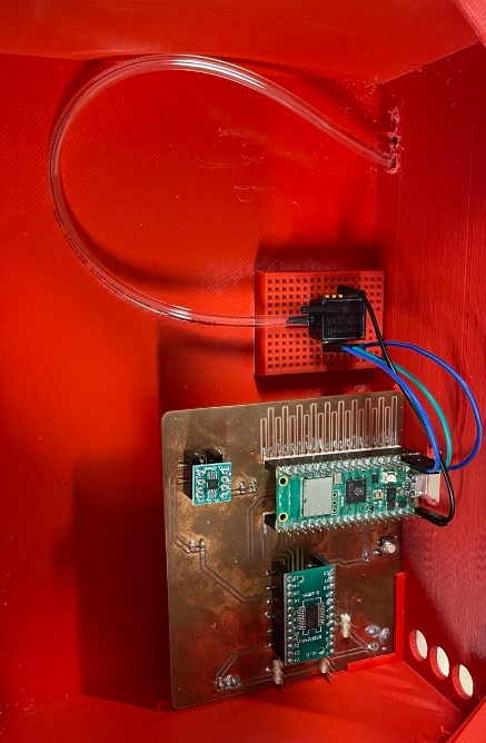
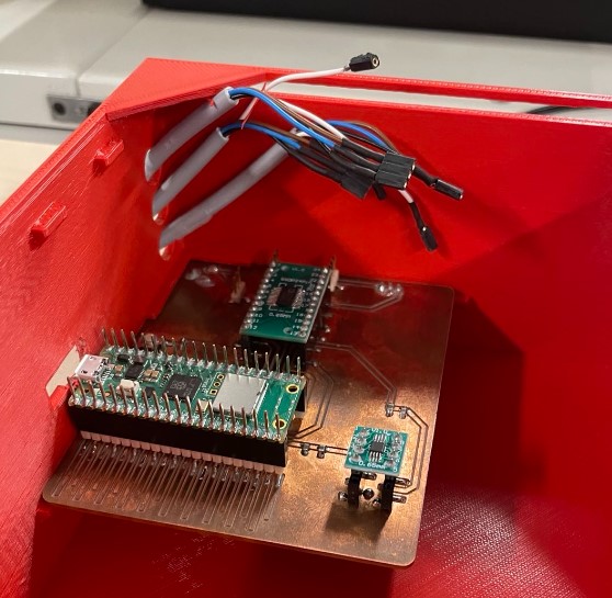
Result
Here is the box with the electronics inside. There is a lot of space in the box because for the moment I have only one pressure sensor out of 3, and I will maybe add other stuffs in the box if I add some functionnalities to my test bench (see the option of the pump and its board for the layer jamming my final project page), but for the moment it’s just an option. At least there is room in the box to add other things later!
Pressure Regulator support
To hold the pressure regulator in one place and avoid the to move due to vibration of the valves inside them, I designed a wood board on which they will be fixed. This board will be raised so cables can be fixed and hided under it, and just pneumatic tubes will be visible and fixed on the board.
On the side of the board, a place will be laser cutted to put the electronic box inside, so it fixed as well.
I made a drawing as before to know where to put things.
Making
I designed it on Solidworks. Then I exported the dxf file of the sketches that I wanted to cut with the laser cutter, and I used inkscape to do the svg file to cut it.

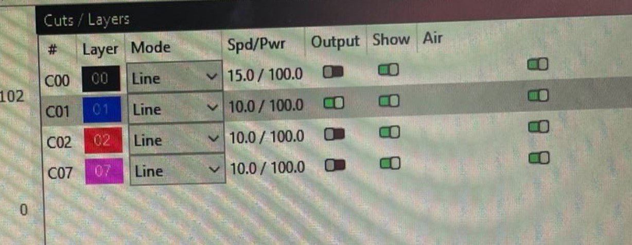
I used the laser cutter for the 4 holes on the corners to fix the plate on the raisers, and the space for the electronic box, as well as a slot for the cables. The laser cutter I used is a FAbKit Mk6, and works with the software “lightburn” for the control. I imported the svg file on lightburn and choose the parameters for the different paths I wanted.
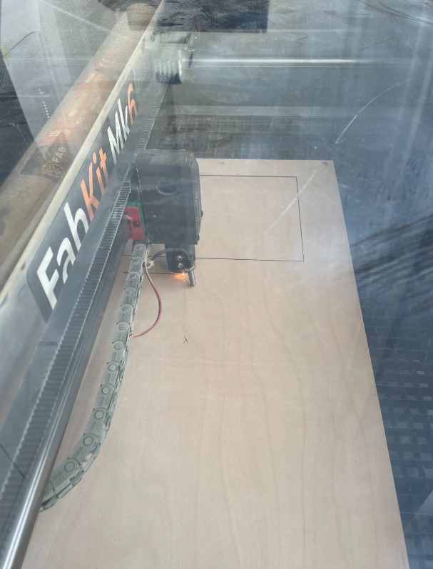
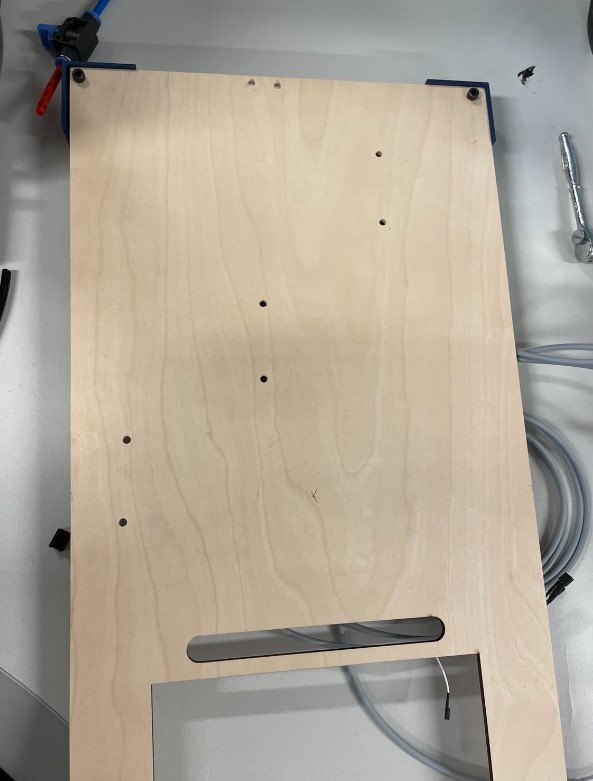
Result after the laser cutting
I already mounted the raiser on the corners:

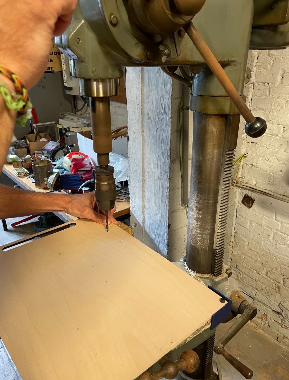
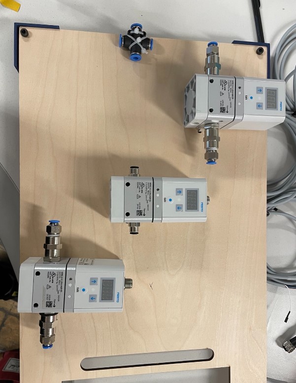
Then I placed the pressure regulators on the plate and I drilled holes where I wanted to place them. I didn’t did it with the laser cutter because it was easier to organize the stuffs as I wanted directly on the board, rather than doing it on the paper and design it with solidworks. Geoffrey, the technician of my lab help me to drill the holes.
Assembling
For the assembly I followed the steps bellow:
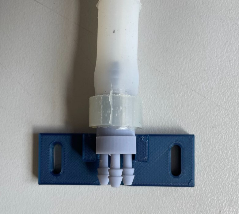
1) Assemble the pressure regulators on the board as well as a pneumatic connector. I used Colson rings to do that.
2) I attached the cables of the pressure regulators behind the wood board, using again some Colson ring and some 3D printed cable holder that I have found on here and that I have adapted for my cables size. I stuck the holders on the board with double sided tape.

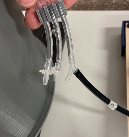
3) I added the pneumatic tubes on the board. I used again some 3D printed holder cable.
4) I did some labelling to know which pressure regulator I will control. I have also labelled the pressure regulator from 1 to 3 in the code that I use to control the pressure regulator with my electronic board, so each one will be connected to the correct connector on the board.

5) I connected the electronics.
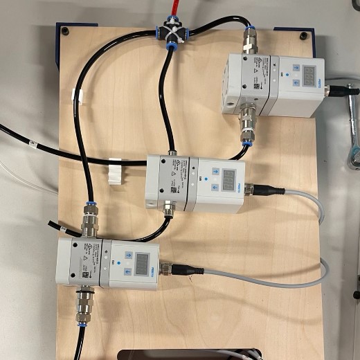
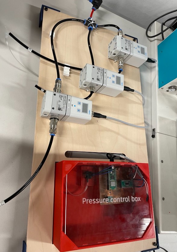
Result
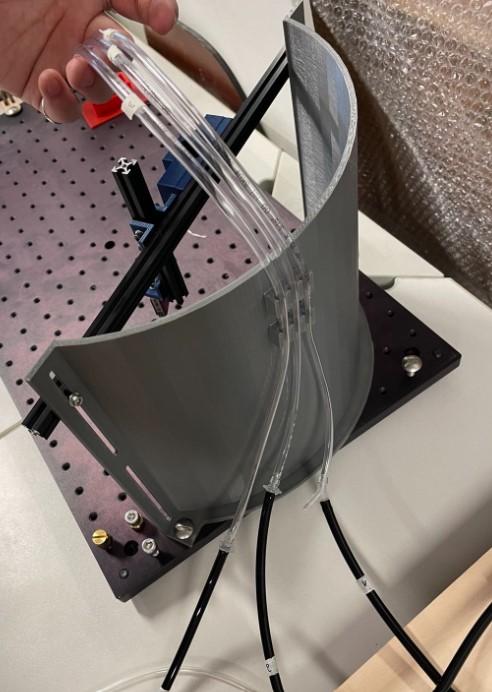
here is the result of the pressure regulators fixed on the board and connected to the electronics. Last step is to connect the pneumatic tubes to the actuator.
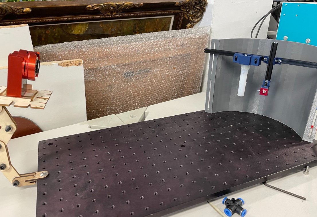
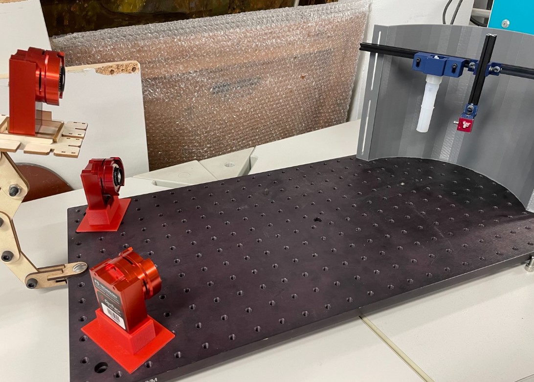
Test bench assembly
I also used this week to assemble the different part of my test bench. The pictures below describe the different steps.
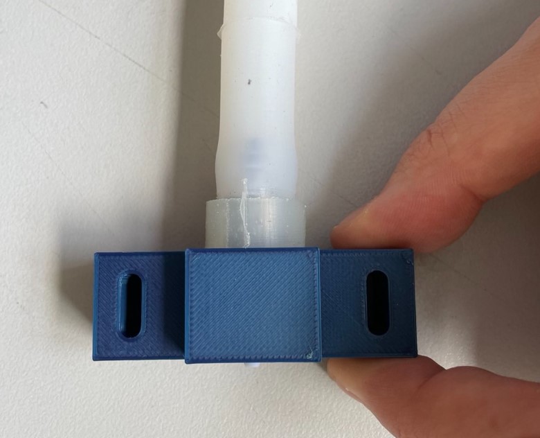
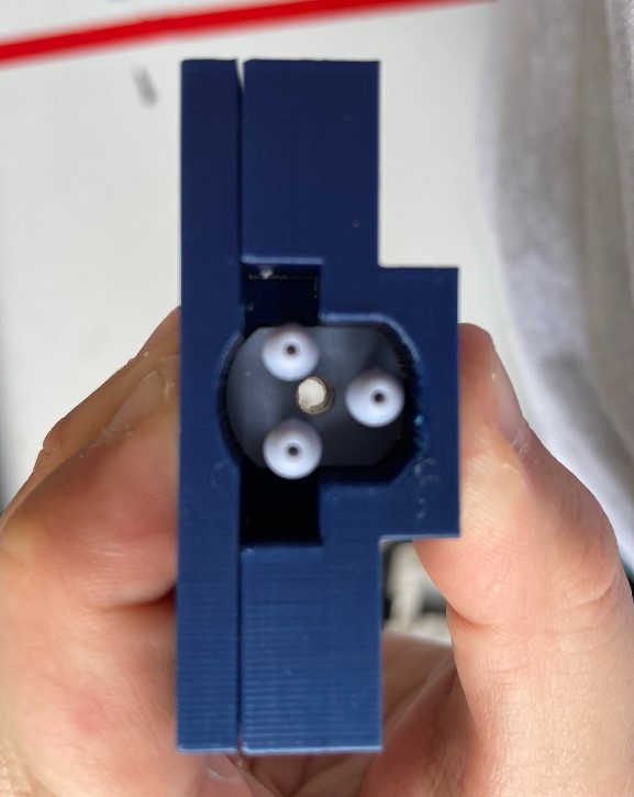
1) Fix the actuator on the 3D printed actuator holder that I designed during week 2.
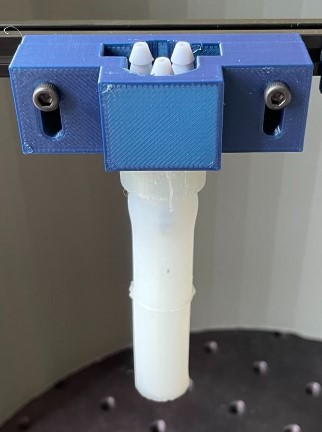
2) Attach it on the aluminium extrusion and on the background structure with the corners connectors that I designed during week 2. I also attached the load cell on its structure.
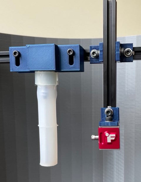
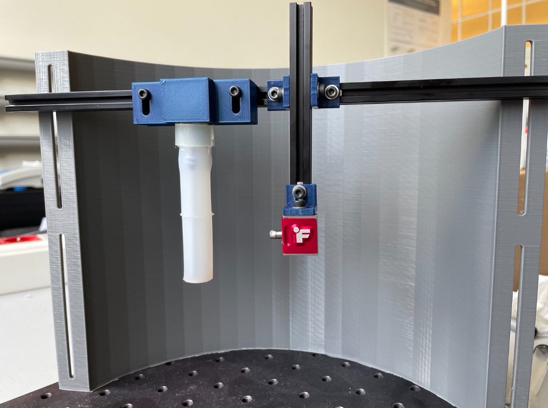
3) Attach the camera
4) Link the control pressure board to the pneumatic actuator