Week 10-11: Mechanical and machine design
For this week assignment, the main documatation will be done on the group page, but the part that I have done during the week will be put on this page too.
Hero shot
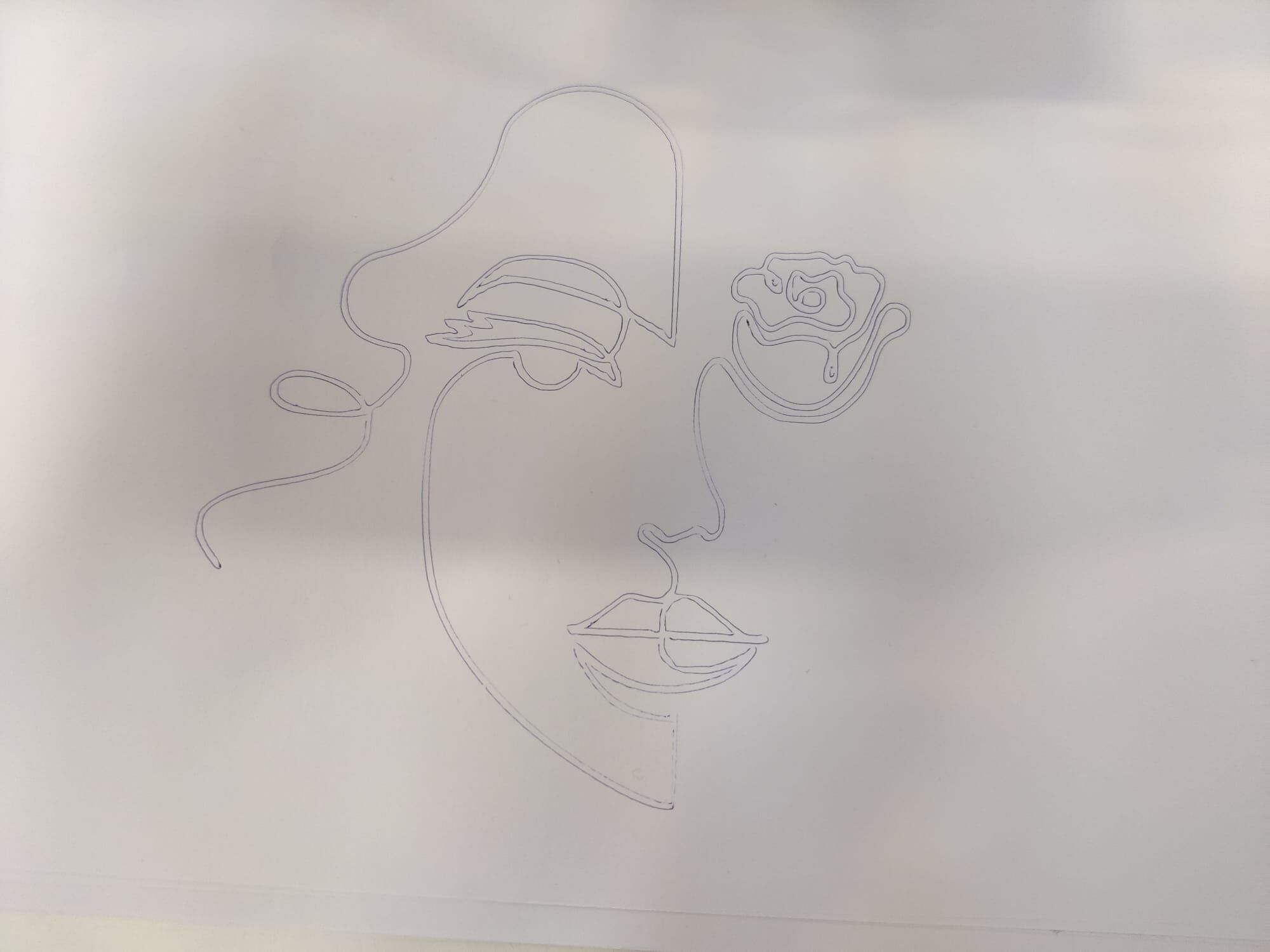
Here is a video ofour machine working and drawing:
Urumbu machine
The machine that will be developped this week by our group is a version of the Urumbu machine, that we will try to improve with some changes. Our version will be based on the Urumbu 2022 version, but the goal is to add the possibility to change the end-effector easily, to have a modular tool head.
Tasks repartition
There are mainly 2 functions to be developed, each of which can be divided into three themes: mechanical development, electronic development, and software development.
The two functions are the 2-axis system, and the modular tool head.
The distribution of topics was worked out together, with each person taking responsibility for a part of the project. This is described in the table below.
| Function | Development | Who |
|---|---|---|
| 2D axis system | Mechanical Electronic Software |
Teo & Charlotte Bogdan Siméon |
| Modular tool head | Mechanical Electronic Software |
Luis Alex / |
I will thus focus on the manufacturing and assembly of the 2D structure of the machine, as well as improving the design if needed.
Mechanical structure
Recreate the existing 2D axis of the machine
With Teo, we did a first iteration of the mechanical structure, by using the files already available on the gitlab of the Urumbu 2022 fall project. Our first focus was indeed to make a good documentation to recreate the Urumbu 2D axis structure, and try to have a working structure for our group, before trying to make some changes/improvements to the structure. This documentation can be found on our group page.
The main modification that we did was to adjust the dimensions of some parts. Indeed, when we assembled the plate with the wheels on the rails, there was a small gap between the rail and the wheels, even with the adjuster that allow to reduce that gap as explained on the group page. We thus reduced the space between the wheels, so that the gap will be reduced. We did the modification directly on Inkscape, when creating the svg file from the dxf file downloaded on the gitlab. By reducing the X position of this hole, it will shift the hole to the left and thus reduce the space with the 3 other holes that we can see on the picture.

Results
We can see a video below of the mechanical structure working after the assembly, before adding the motor and the control.
Z axis
We add a Z axis based on some existing design in the urumbu git lab.
The idea is to have a Z axis mounted on a structure on the existing 2d axis structure, which allow to keep the modular idea of our machine. If a third axis is needed, the tool is fixed on the Z axis, and the working bed is fixed instead of the tool in the 2D axis.
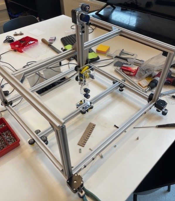
Here is a picture of the final structure that we obtained.
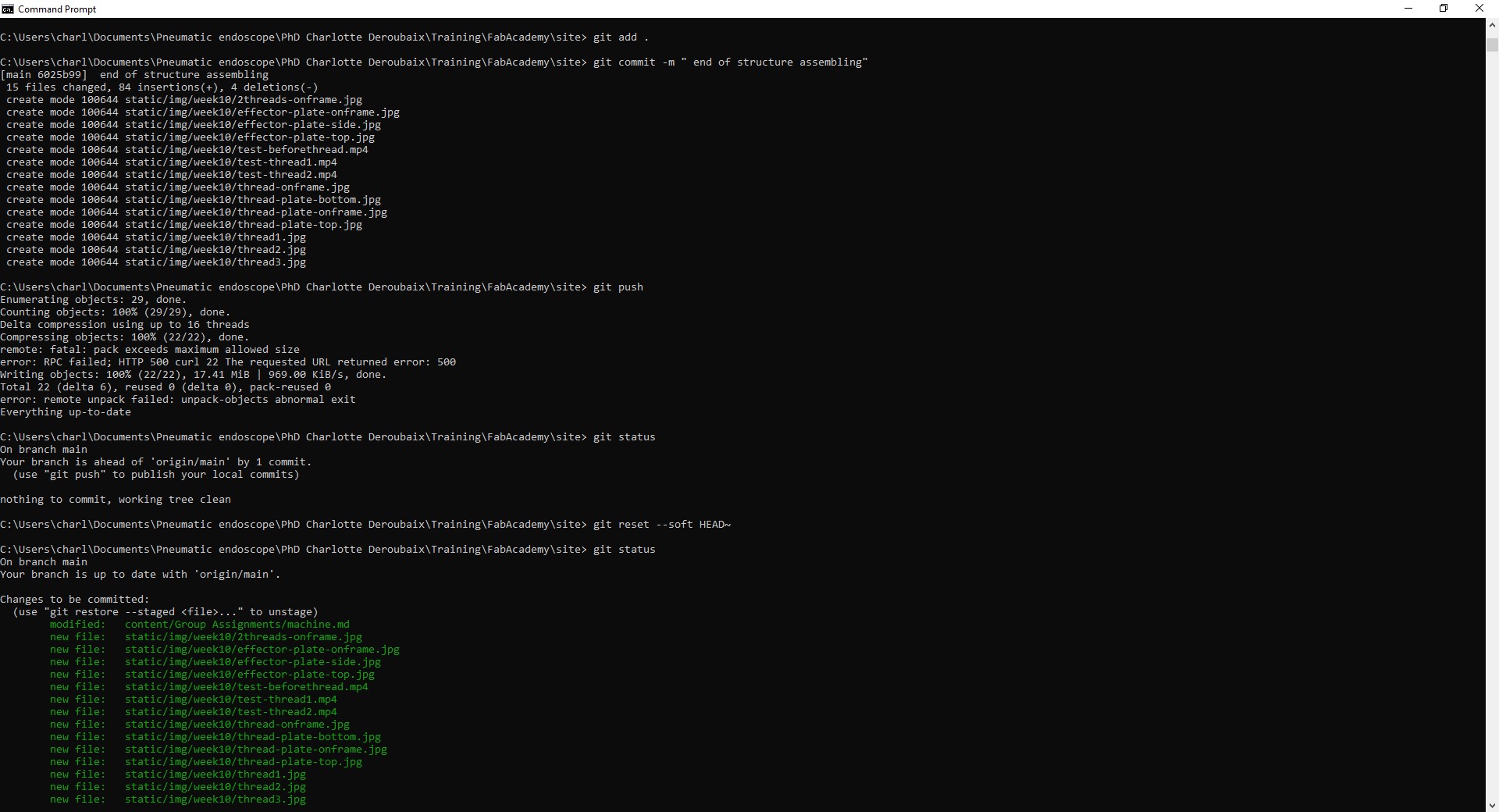
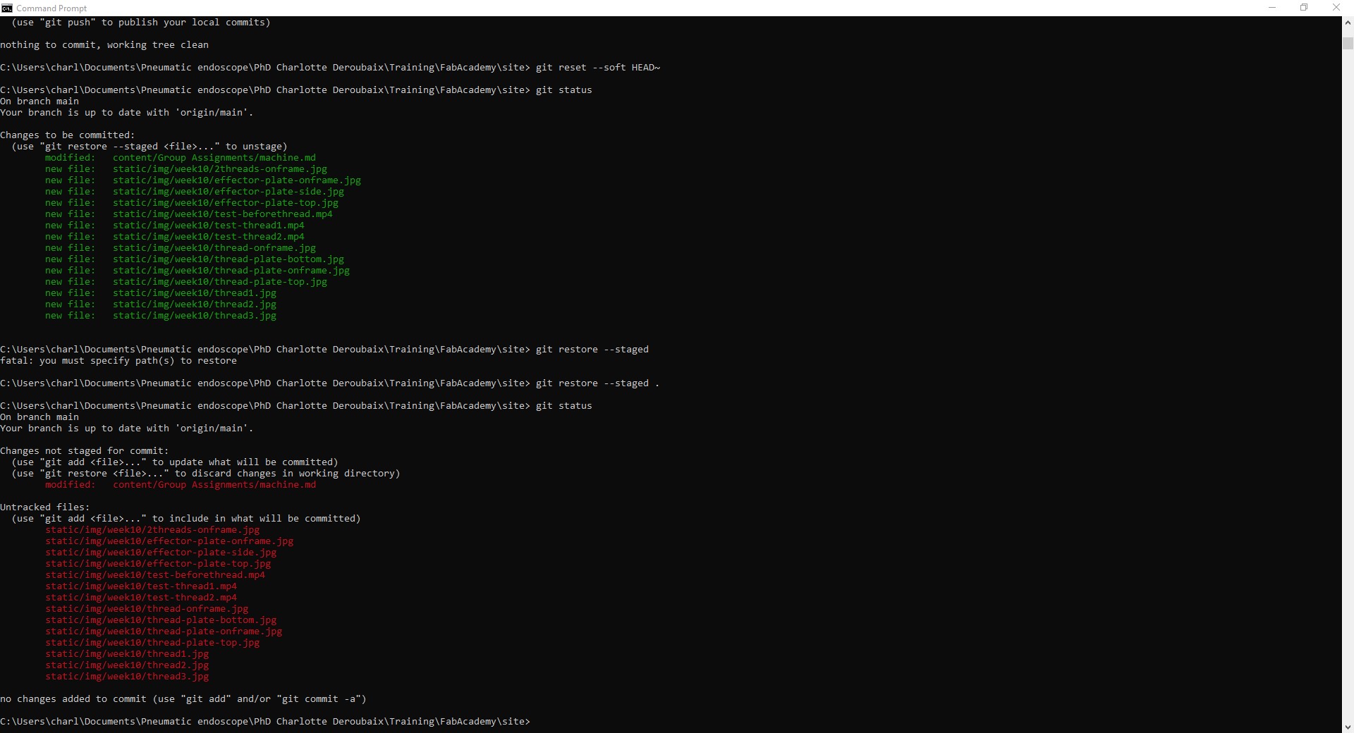
To big commit on git
When documenting the group page, I did a too big commit due to the size of the video. I document below how to resolve the problem.
git reset --soft HEAD~
then
git restore --staged .
Midterm progress and planning
We’re already halfway through the Fab Academy, so it’s time to take a look at what’s already been achieved for my final project and what’s still to come.
What have been done
Pressure control system
The pressure control system is done and tested, it is ready to be assembled on the test bench!
It has been developped mainly during week 8 where i developped a PCB allowing the communication between my computer and the pressure regulators and week 9 where I tested the PCB and checked that everything were working. I am now capable of sending analog voltage commands ranging from 0 to 10V from my computer to the pressure regulator, in order to control the pressure inside the air chalbers and thus the bending of the pneumatic actuator.
Everything is summurized on the test bench page of my final project.
Mechanical structure
During the week 2, I already started to work on my final project by designing and thinking about the different parts of the mechanical structure of the test bench. During week 3 I also designed parts to hold my camera in the test bench and I cut them using a laser cutter.
I printed it and it’s now ready to be assembled.
Prototypes
I didn’t do a lot for this part, except during week 5 where I 3D printed some pneumatic connectors to link the pneumatic actuator to the air supply system.
What I need to do
I still have a lot to do, especially on the prototyping side. Here’s the list of things I’ve still got to do, with a timetable of when they’ll be done.
Things to do:
Prototypes
-
Test the layer jamming: Before constructing the layer jamming for the pneumatic actuator, I want to do some tests to find the best way to create a membrane that will embedded the multiple layers, as well as to find a good way to fix and seal the vacuuming tube to the membrane.
-
Molding and casting: During the molding and casting week, I plan to design and construct a mold for my pneumatic actuator. The mold will be composed of multiple parts, and the goal is to be able to produce multiple pneumatic actuators at the same time.
-
Do a full prototype: Once I’ve finished the above task and made some pneumatic actuators during the molding and casting week, I’ll be able to assemble the two structures and build a complete prototype.
There will be iteration on those steps so I planned some time for that in my schedule.
Test bench
For the test bench, the remaining tasks are mainly to do a box to embed the electronics and other stuffs, to have a clean test bench. I also need to fix the camera with the parts that I designed during week 3.
Planning
