Bending tracking
Working principle
The bending tracking is used to track the tip of the pneumatic actuator, and then analyze the data recorded to determine the bending angle of the pneumatic actuator in function of the pressure applied inside the air chamber.
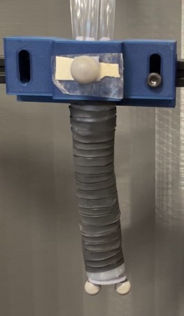
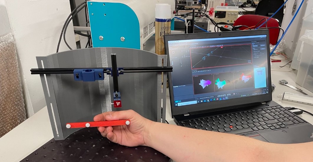
The tracking is done thanks to 3 OptiTrack camera flex 3 and the Motive software from OptiTrack. The cameras emit infrared light that is reflected by markers and then capture back by the cameras. To track the tip of the cameras, it will thus work as follow: I put 2 markers at the actuator tip that will be tracked when it moves, and 1 fixed marker that serves as a reference. I will get the coordinates of the markers thanks to the Motive software, and I wrote a code that take the coordinates and compute the bending angles. The bending angle is represented by alpha on the picture below.

Markers
To attach the markers, I designed 2 pieces on Solidworks: one for the fixed markers, and one for the 2 tip markers. The pieces have been 3D printed with an SLA printer. They are disposed as shown below on the actuator:
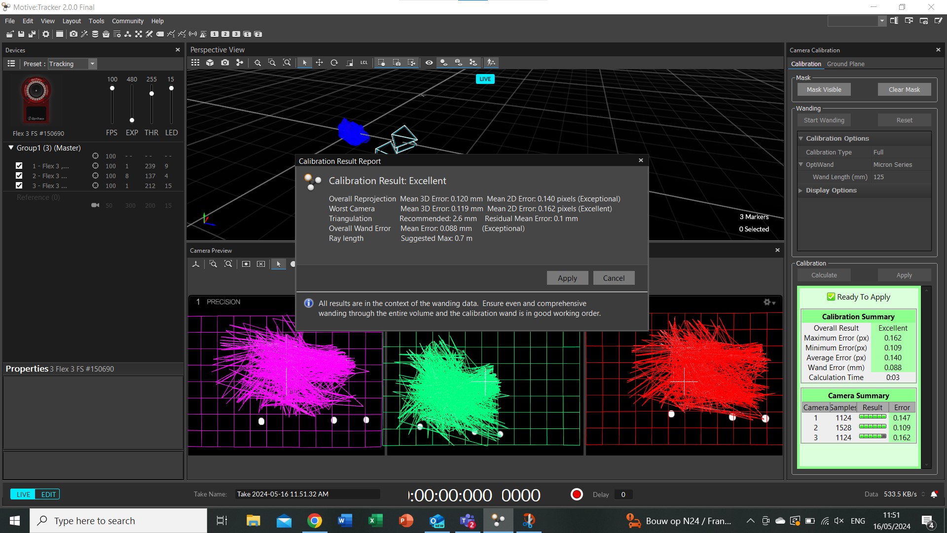
Camera calibration
First step before starting the tracking, is to calibrate the camera in order to define the space in which we are working and the precision with which we will work.
The calibration is done as follow:
1) Adapt the parameters to track only the markers and not other background/noise object
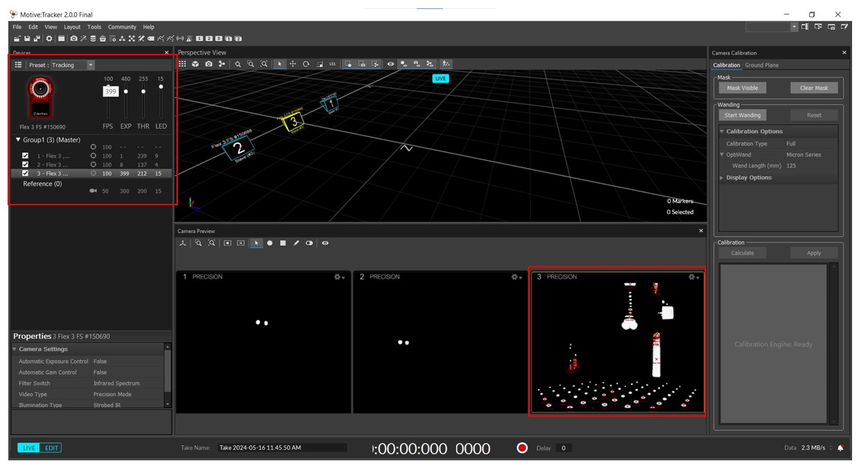
On the mtoive software, you can adapt 4 parameters: the FPS, the exposition (EXP), the brightness threshold (THR) and the LED intensity. Depending on the intensity of each parameters, you can refine the focus on the markers and suppress the background noise, so you can track only the markers you are working with.
Before the expostion adjustement -> exposition high -> lot of undesired objects
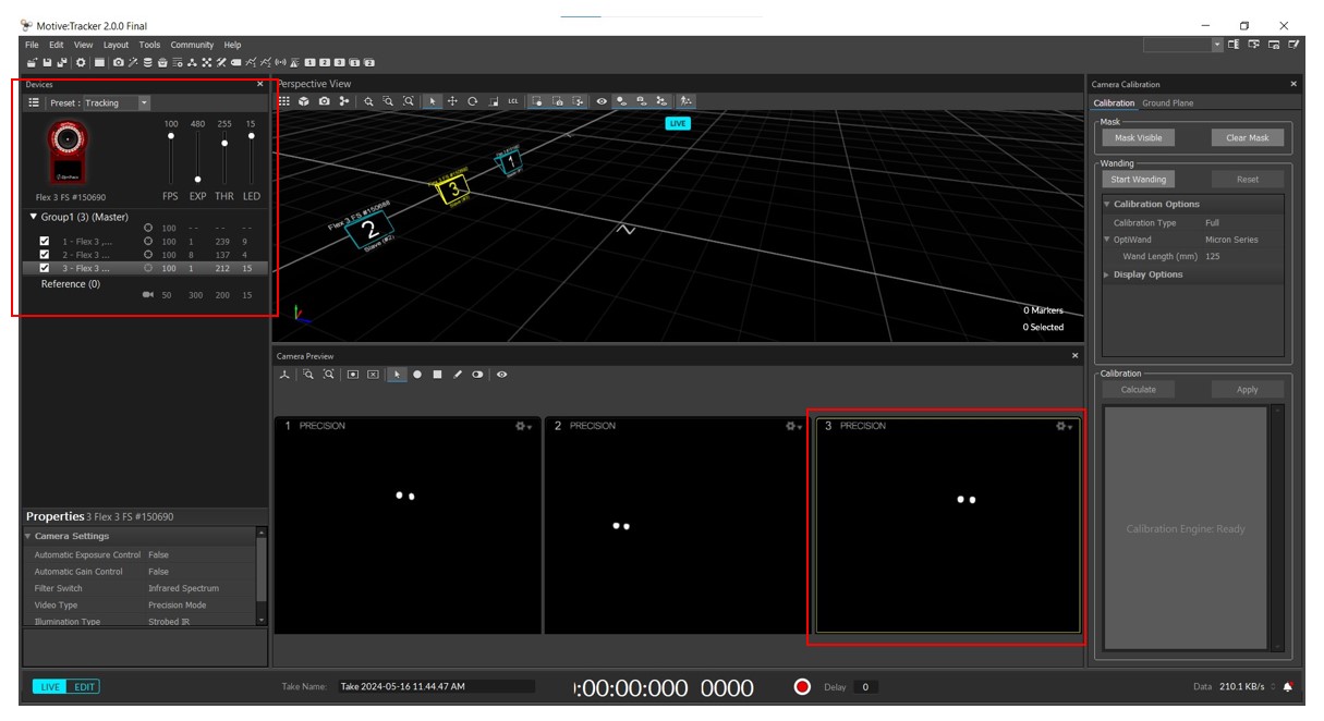
After exposition adjustement -> exposition low -> just the markers are seen by the cameras
2) Start the calibration
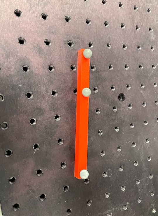
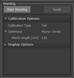
To do the calibration, you need to use a specific wand as shown below with markers on it spaced by specific dimensions. The wand dimensions that you are using must be specified (on the OptiWand Type see below). That’s how the camera will be calibrate and will know how to construct the space in which you are working.
When ready, just click on he “Start wanding button” and start to move the wand in the space that you want to work. It will create colors lines in the camera window, as shown below.
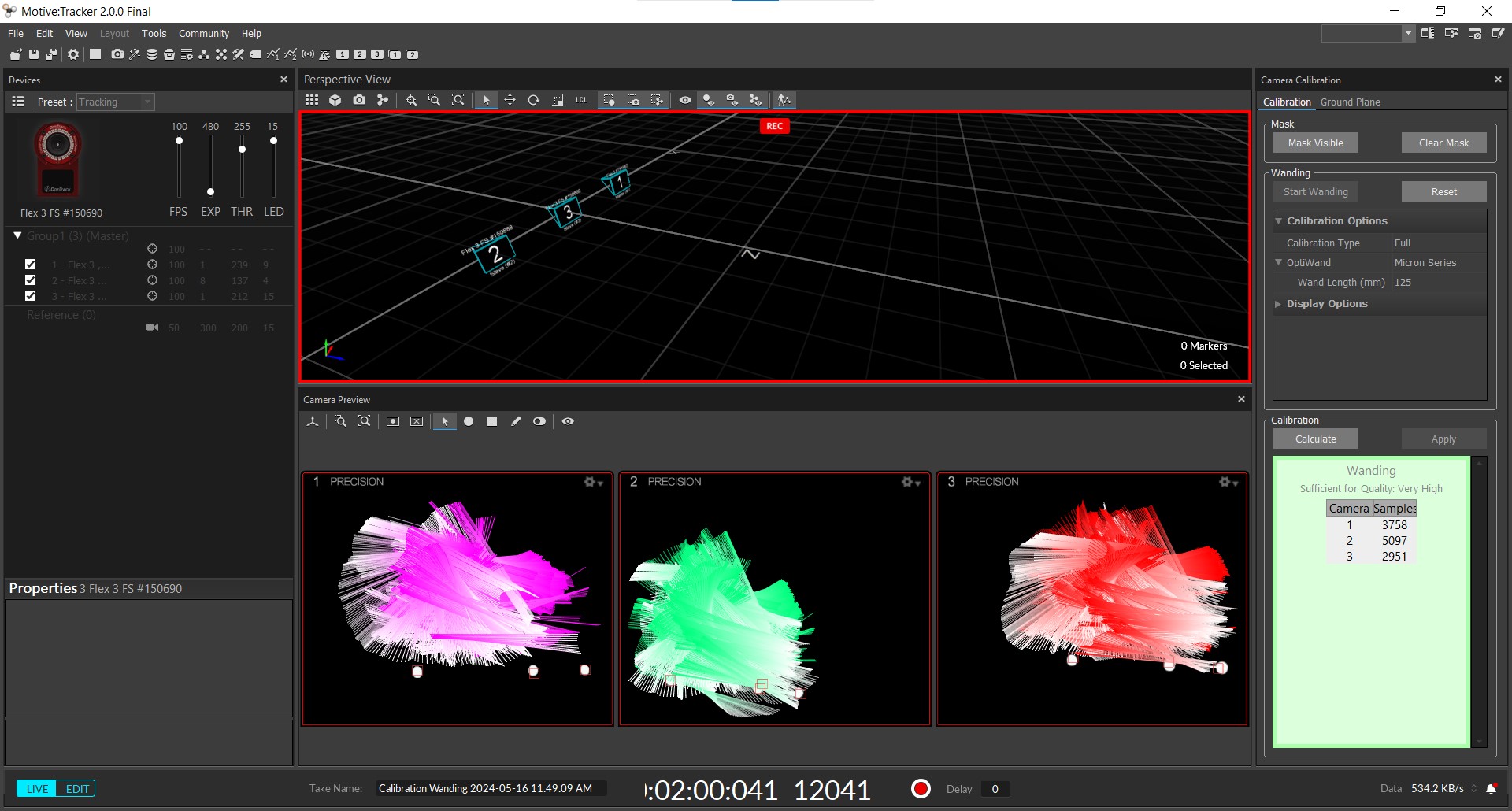
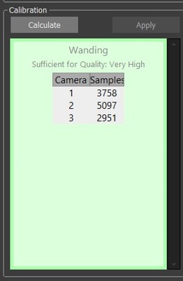
When the calibration quality indicator is high enough, you can stop the wanding/calibration process by clicking on calculate and it will compute the precision with which you are working and other parameters.
Camera tracking
When the calibration is done, you can just start a recording by clicking on the red button on the bottom of the window, and click again to stop it.
Data export
Go in “data pane” and all the recordings that you took will be there. You can look at them there, and you can also export the data. Everything will be exported in a excel file.
Bending angle computing
I wrote a code that find the angle alpha on the picture below:
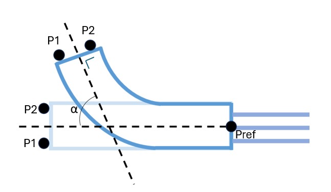
To find the angle, the code execute the step below:
1) Extract the markers coordinates at a time t1 = initial position of the actuator tip markers and a time t2 = final position of the actuator tip markers
2) It computes the plan including the coordinates of P1_t1,P2_t1 and Pref
3) It computes the center of the line passing by the coordinates points P1_t1 and P2_t1, and create a perpendicular line passing by this center and the coordinate of the fix point, Pref, in the plane previously defined
4) It computes the plan including the coordinates of P1_t2,P2_t2 and Pref
5) It computes the center of the line passing by the coordinates points P1_t2 and P2_t2, and create a perpendicular line passing by this center in the plane previously defined
6) It computes the direction vector of the two perpendicular lines
7) It computes the angle between the two
The code can be downloaded here
This code is working in a 3D space. The angle as been validated in a 2D space first by using image analysis with a second code.
Validation code, using python and opencv for the image treatment:
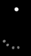
1) Take an image with the initial markers position and the final position, as the one below.
# Import the image
image = cv2.imread('C:/Users/charl/Documents/Pneumatic endoscope/PhD Charlotte Deroubaix/Training/FabAcademy/project/camera/0.65bar.jpg')
gray = cv2.cvtColor(image, cv2.COLOR_BGR2GRAY)
2) Detect the circles present in the image. The detection can be improved by changing the parameters in the “HoughCircles” function, here is a forum link that gives a “rule” to improve the definition of the parameters to detect circles on a wide range of images. In my case, I found parameters that were working by trial and error.
# Reduce noise for a better circles detection
blurred = cv2.GaussianBlur(gray, (5, 5), 0)

# Circles detection
circles = cv2.HoughCircles(blurred, cv2.HOUGH_GRADIENT, dp=3, minDist=5, param1=100, param2=30, minRadius=1, maxRadius=50)
3) Ask in the terminal which point should be considered (1&3), and draw a line between the 2 points, find the center of this line and draw a line between this center and the point 1.
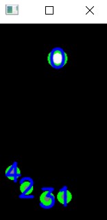
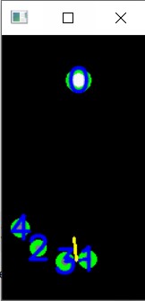
4) Ask two new points (2&4), draw a line between the 2, find the center of this line and draw a perpendicular from that point and perpendicular to the line from 2 to 4.
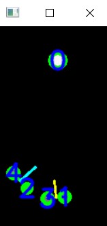
5) Angle of intersection between the 2 perpendicular lines is computed

The code can be downloaded here