Week 4: Electronics production
Assisgnment of the week
Group assignment:
- characterize the design rules for your in-house PCB production process
- send a PCB out to a board house
The group assignment can be found on our fablab web page.
Individual assignment:
- make and test a microcontroller development board
- extra credit: personalize the board
- extra credit: make it with another process
Hero shot of my board

Milling the board
It was my first time ever making a PCB, so a lot to learn this week!
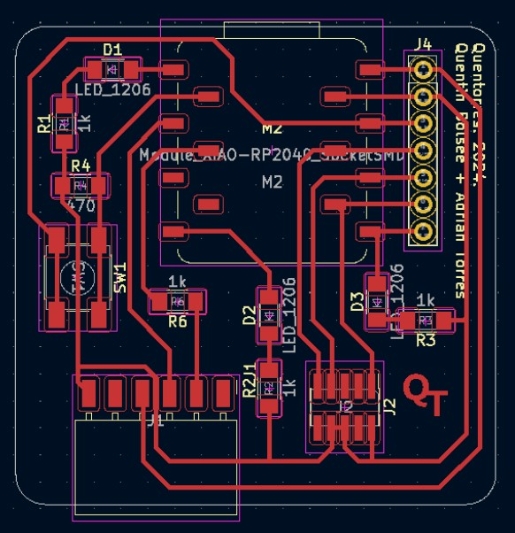
The personnal assignment goal was to reproduce the microcontroller development board of the Quentorres project.
First of all, with the advices of my instructors Nicolas and Axel, I choose to replicate the second option of the board, which allows to remove the microcontroller (XIAO RP2040) of the board rather solder it directly on the board. The idea is indeed to not loose a microcontroller if something else goes bad on the board.
To replicate the board, multiple options is possible, start from the png file given on the webpage (as it has been done for the group assignment) of the Quentorres project, or start directly from the KiCad file. Here, my instructors made some small but interesting changes on the design, so I choose to start directly from their KiCad.
| Quentorres design | Quentorres design modified by Nicolas |
|---|---|
 |
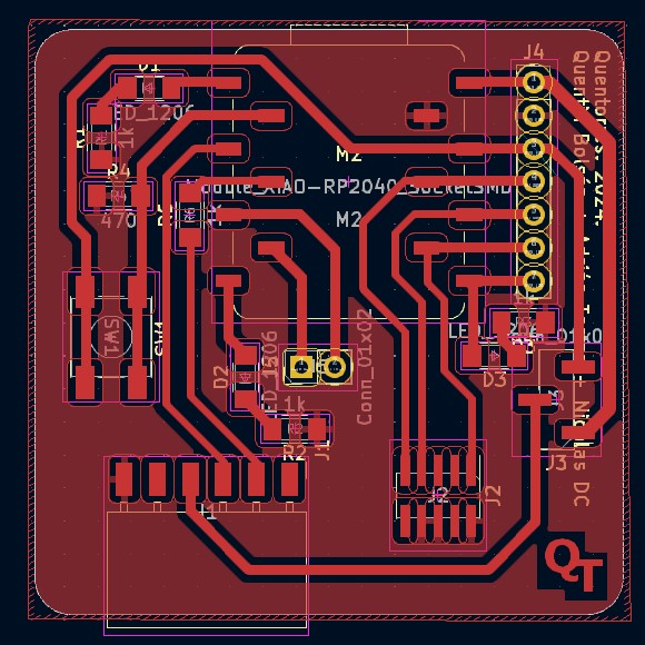 |
Differences between the Quentorres design and Nicolas design:
- Bigger traces so it’s easier to solder the components on it
- Possibility to change from a 3.3V to a 5V
- Make 2 pins available
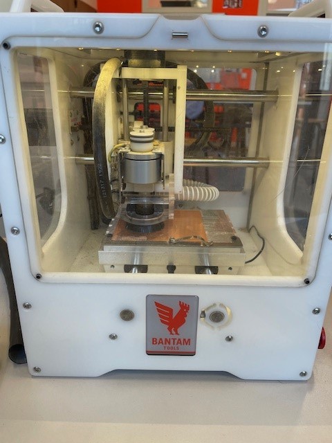
How to start the milling with the Bantam milling machine:
| Steps | Description |
|---|---|
| 1. Open Bantam software | |
| 2. Import the gerber file (“.grb”) | 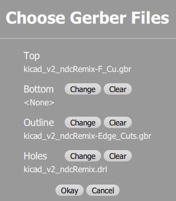 |
| 3. Select the tasks that will be done | Here I begin by doing the traces and the holes tasks, so I have not selected the outline task. I want to make sure that the firsts 2 are well done before cutting my pcb from the rest of the board. 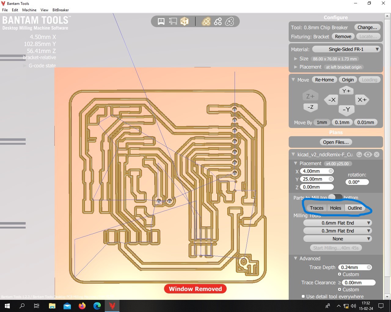 |
| 4. Define the different milling tools needed depending on the traces sizes | Here, most of the traces have at least a 0.6mm tickness, which means that we can use a 0.6mm flat tools for most of the traces. However, some parts of the design are very thin and require a smaller diameter tool. That’s why here the software is asking for a smaller tool for the red parts. I have thus add a 0.3mm flat end tool. The software will begin by doing the traces with the smaller tool and then it will ask to change the tool to finish the traces. It’s better to use larger diameter tool for rapidity and to remove more material in one passe. It has also less chances to break. 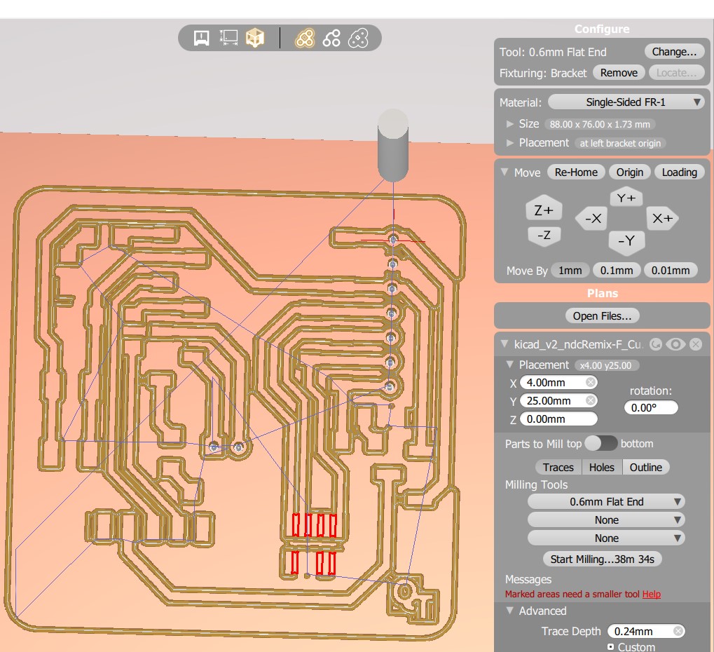 |
| 5. Determine the traces passes parameters | Here: trace depth defined to 0.24 mm after testing 0.2mm which was not enough. The board was probably not well placed in the machine, resulting in parts lower than other. |
| 6. Follow the steps of Bantam software (calibration of the z axis depending on the tool, change the tool,..) | Everytime the tool is changed, the software do a calibration to know the height of the tool. The calibration is done on the martyr, so the tickness of the material should be put in the setting as well (here 1.73mm). |
| 7. Start the milling | 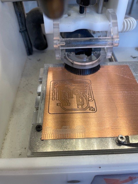 |
| 8. Cut the PCB from the board | Once the traces and the holes are well done, the PCB can be cut. This time, the “trace” and “holes” task are unselected and the “outline” task is selected. The tool need to be changed as weell. This time, i used a 0.8mm flat end tool. 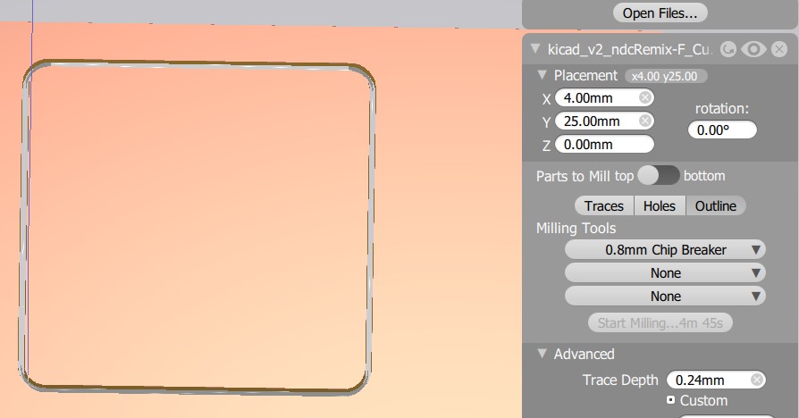 |
The gerber files can be downloaded here.
If I didn’t use the KiCad file, I could have use the mods to obtain a gcode from the png file or I could have use inkscape to make a svg file from my png file and to use the Bantam software after that. We used mods during the group assignment.
Results:
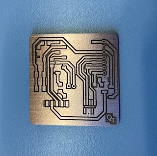
I tested it with a multimeter to be sure that all the connection are good. It was ok in my case so I went for the next step: soldering the components.
Soldering the components
The list of the components needed is available on the Quentorres project, it includes:
- 1 SEEED STUDIO XIAO RP2040
- 1 CONN HEADER SMD 10POS 1.27MM
- 1 CONN HEADER SMD R/A 6POS 2.54MM
- 1 Tactile Switch SPST-NO Top Actuated Surface Mount -> I took one available in my fablab
- 3 LED BLUE CLEAR 1206 SMD -> no more blue led available in my fablab so I went for green led
- 4 RES 1K OHM 1% 1/4W 1206
- 1 RES 499 OHM 1% 1/4W 1206
- 2 CONN HDR 7POS 0.1 TIN SMD* -> replaced by male connectors on the board and female connectors based on an advice of my instructor, because its cheaper in that way.
I have started by the resistor and leds, then push button and I have finished with the different connectors.
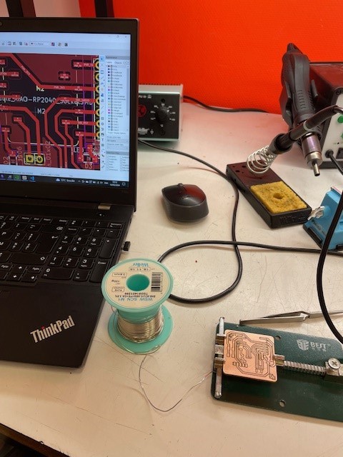
I did the soldering while looking at the KiCad file to be sure of the placement of the different components, as well as the orientation of the led. I have first tested the led to know the diode and cathode position, and then soldered it as indicated on the file.

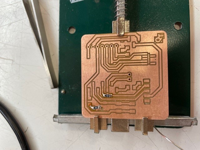
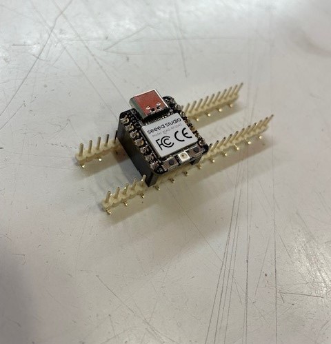
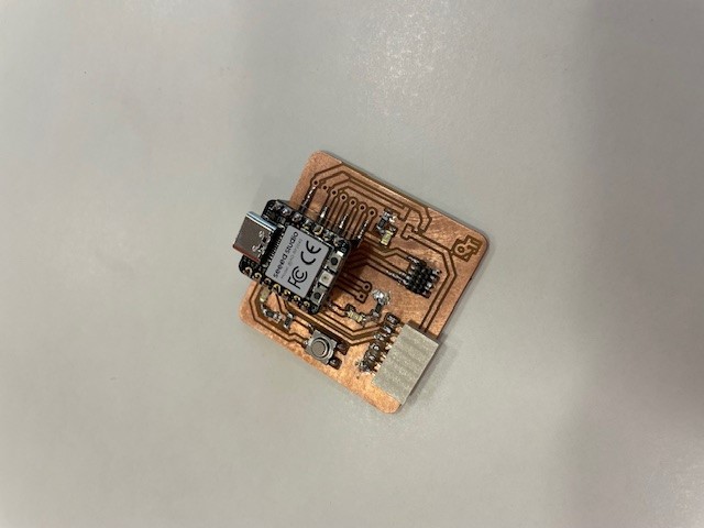
Results: final board after soldering
Testing my board
Blinking led
To test my board, I want to light on the LED. I have followed the tutorial on the Quentorres project website.
- Download arduino app
- Open the app -> file -> preferences -> add “https://github.com/earlephilhower/arduino-pico/releases/download/global/package_rp2040_index.json” in the “Additionnal Board Manager URLs” (link found here)-> click ok
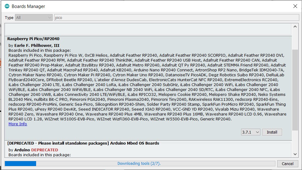
- Tools -> Board -> Boards Manager -> search “pico” and install it.
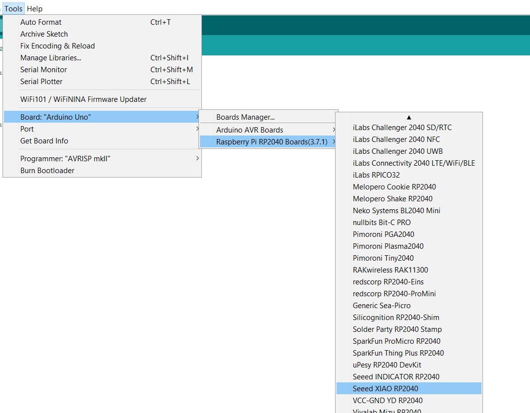
- Configure the Arduino IDE for the Seeed Studio XIAO RP2040
- Blink : file -> examples -> basics -> blink (chose the good port, me: COM7 Raspberry Pi Pico))
Does not work at first -> check all the soldering again with a multimeter, nothing wrong....
I have put the wrong pin number on the code… basic beginner mistake.

Update week 6
In week 4 when I tested my board, the LED intensity was very low, I didn’t know why at the time. In week 6, when programing and testing my code, I realise that one of my soldering was very bad (cold joint), and it led to a very low current, which is why my LED wasn’t very bright. I did my solder again, and now everything is good!
Use my board as a programmer
As a second test, I wanted to use my board as a programmer, so I followed the 3 steps on the Quentorres gitlab to do that.
My instructor Axel had a UPDI target available to test my board, so I went for this option.
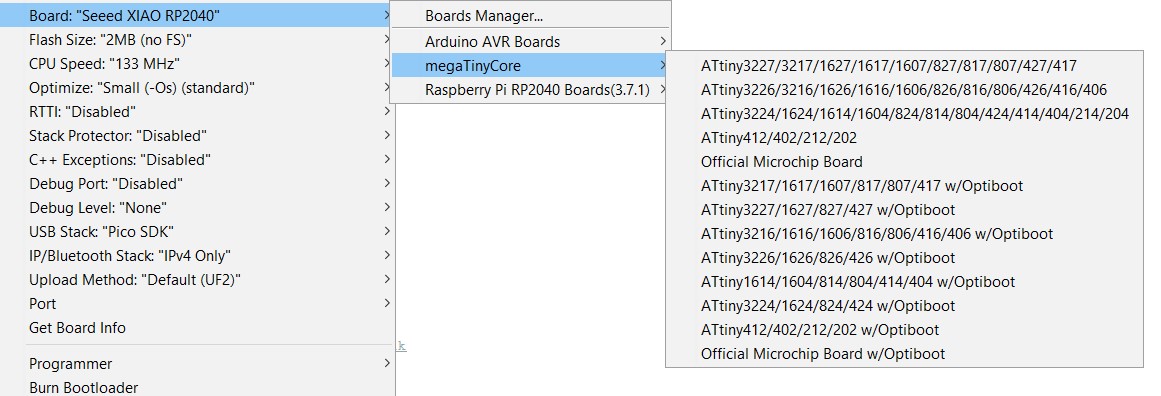
- Install MegaTinyCore (link) -> I used the manual installation because the other way doesn’t work: download the master .zip file -> extract -> copy it on the hardware file of Arduino folder.
-
Put the pin 4 which correspond to the one of the led on the ATtiny board.
-
Upload the code -> does not work because it can not load python 3.

I went into “megaTinyCore-master\megaavr\tools” and opened “ManualPython” -> followed the instruction to put python 3 in tools -> working
- New error :(
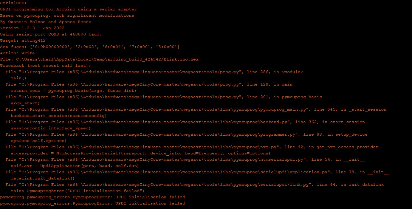
To be fixed.. On the Quentorres gitlab, there is some issues that have been reported when flashing a UPDI target, I could try this.
Video MP4
I used VLC converter: open VLC -> media -> convert/save -> Add the file -> convert/save -> choose the type of file you want