Week 7: Computer controlled machine (CNC)
Assignment
Group assignment
- lab’s safety training
- test runout, alignment, fixturing, speeds, feeds, materials, and toolpaths for your machine
-> assignment group on our fablab webpage
Individual assignment
- make (design+mill+assemble) something big (~meter-scale)
- extra credit: don’t use fasteners or glue
What I did
A bed table that I designed without fasteners or glue.

Design, mill and assemble a bedtable
Since a long time, I’m using a stool as my bedtable, but this week is a good opportunity to finally have a proper bedtable! I took some measurements of the space I have near my bed, some inspiration on internet, and I designed my bedtable on Fusion 360.
Design
The bedtable will be composed of 4 parts: 2 lateral parts as the main structure, and 2 stages to put some books or other stuffs.
Lateral parts
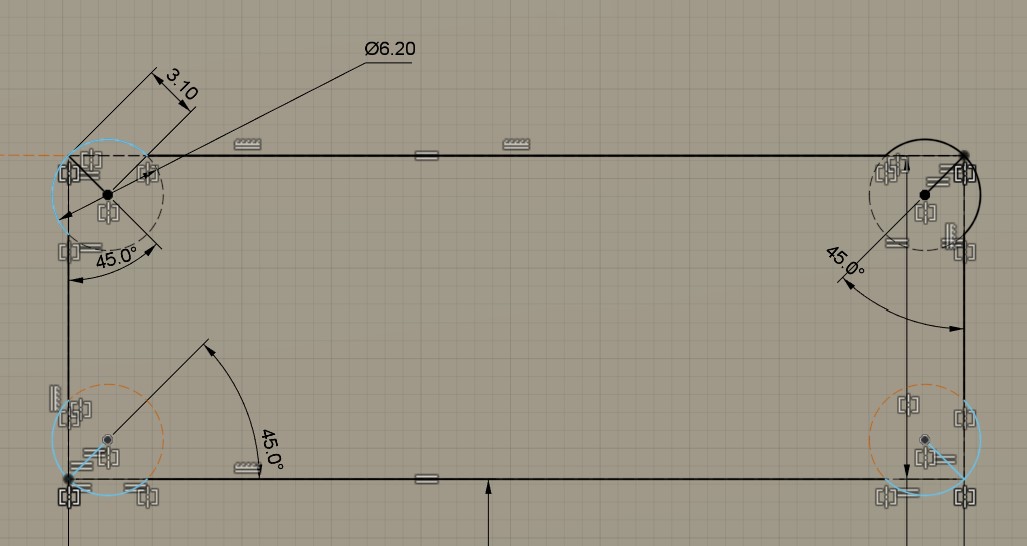
I started by designing the structure, then I add some chamfer on the coin to be more esthetic and finally I add some “dogbone slots” in order to fix my stages without glue or screw.
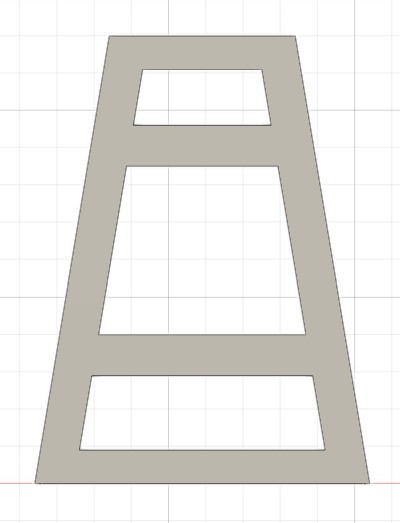
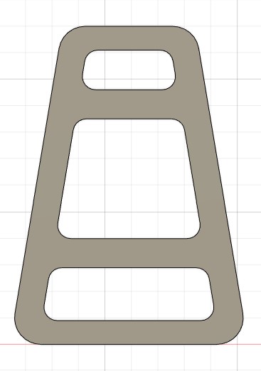
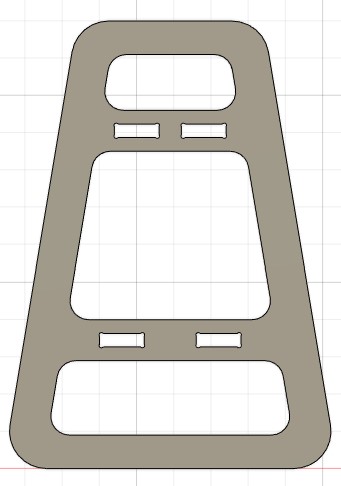
The dogbone slots are used because the slots can not be made rectangular due to the cylindrical tool used for the milling. Here the skecth of the dogbone is shown. I will use a tool of 6mm so I chose a diameter of 6.2mm for the circles in the corner of my rectangle.
Stages
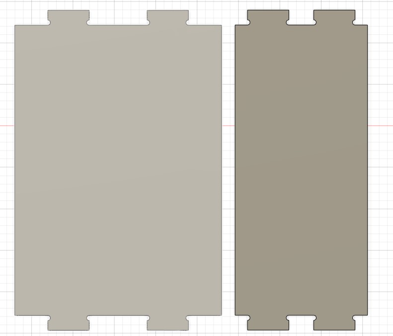
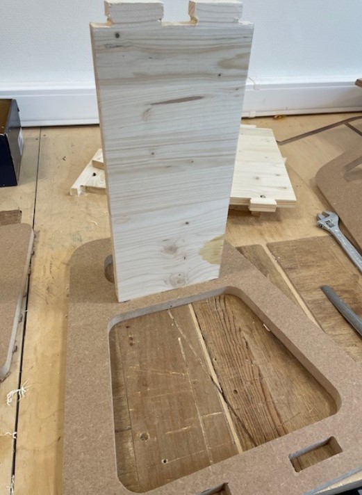
The design of the stages are very basic, it’s just 2 rectangles of different width, with parts that will be inserted in the dogbone slots for the fixation.
Source files
The design source files can be downloaded here.
Milling
When using a CNC machine, the design is the easy part of the job, but then there is still a lot of work to do before going to the milling process. It is my first time using a CNC machine so all of the steps to prepare the gcode, i.e. the code that will describe the path of the machine, will be developped here.
I used Fusion 360 to design my part because the software also has a very good “manufacturing” tool that allow to generate toolpath for the milling.
Step 1: defining the set up
The set up will define the working model, stock size, fixtures and also the working coordinate system. It’s an important first step to define everything properly.
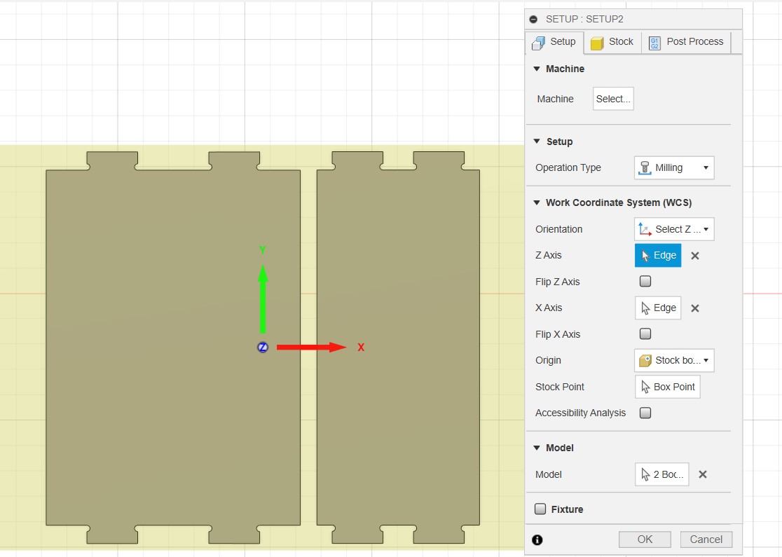
- Defining the coordinate system
The coordinate system during the milling process and the one used to design the part are not the same. The first thing to do is thus to define the coordinate system in which we will work in the CNC machine. To do it -> select Z axis/plane & X axis -> select corner or face of our model to define the coordinate system in the same orientation as the one of the CNC machine. An origin should also be defined, it’s the place where the tool will start the job and more importantly where the zeroing of the machine will be done in order to know iuts position in the working area. A point of the raw material can be selected or one of the body to cut. I placed it on the top of the material, on the middle of my part.
- Defining the stock size
On the stock tab, you can specify the dimensions of the raw material that will be used. It will draw a yellow rectangle with the specified dimensions.
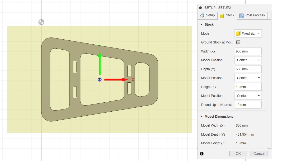
It’s obviously better to not do the same thing as me: the part to cut is in the middle of the raw material and I will lose a lot of material in the extremities -> as I chose the origin as the center of my part, I will just shift it in one of the extremities when marking the origin on my raw material.
Step 2: define the milling paths
When the first part is done, milling paths can be created. In my case, I don’t have any pocket, engraving or slot in my parts, I just need to cut through the material. To do this, I created a toolpath based on a 2D contour (2D -> 2D contour).
Tool
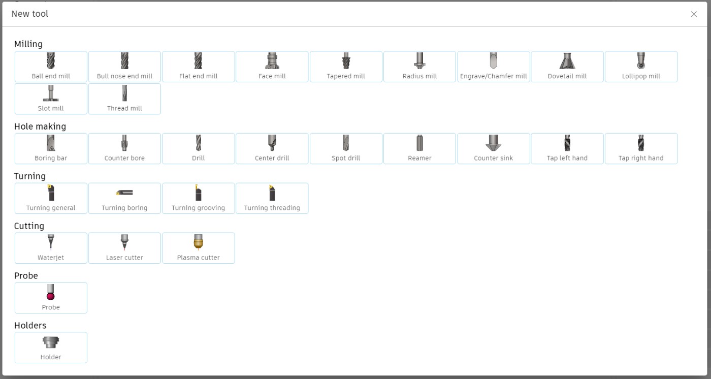
On the parameters window, first thing is to choose the tool that will be used for the job: select tool -> window appear and a existing tool can be chosen or a new one can be created. As I never used the manufacture tool, no tool existed so I added one.
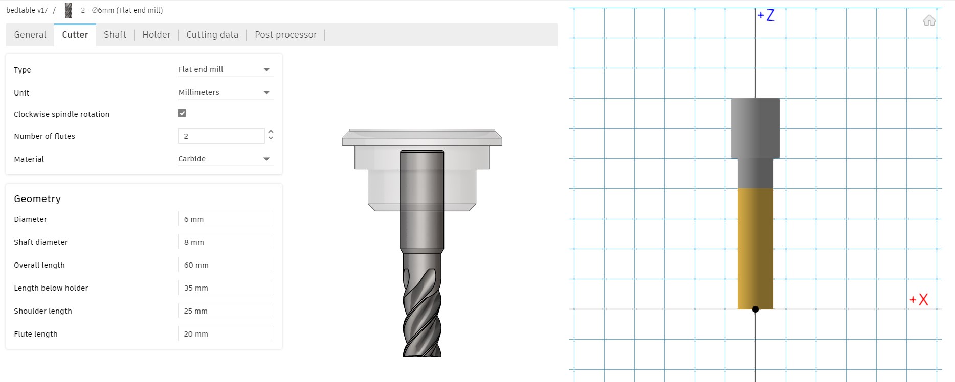
The cutter parameters can be found on the tool package.
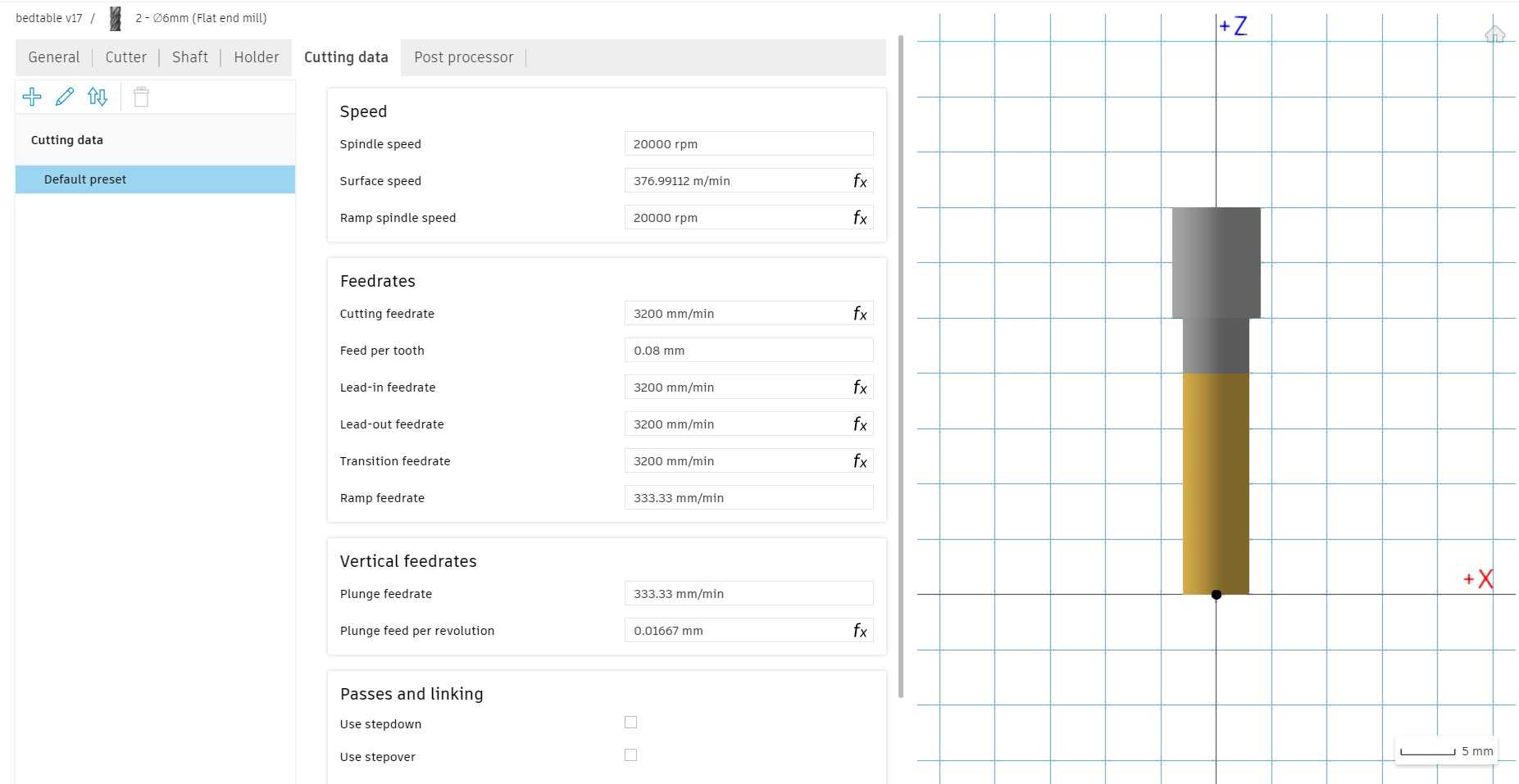
The cutting data are very important for the programmation of the gcode and must be chosen carrefully. The different parameter will have an impact on the machining timing, which should be minimized but without breaking the tool. The parameter depends on the type of material that is cut and the tool.
| Parameter | Description |
|---|---|
| Spindle speed | It’s the rotation speed of the tool, in rotation per minute |
| Cutting feedrate | It corresponds to the linear velocity of the end of the cutter, representing the speed at which the cutting edge is introduced into the material, in mm/min. It’s chosen based on the material -> here MDF and fir wood -> between 2000 mm/min to 3000mm/min |
| Feed per tooth | It’s the amount of material each toooth removes per spindle revolution. It’s chosen based on the size of the recommended chip size of the material (0.4mm for the wood), and the recommandation of the tool vendor. It’s thus chosen based on the recommandations and to be as close as possible to the recommended chip size. 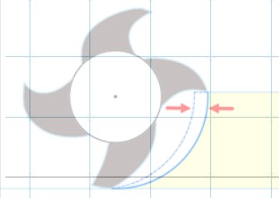 |
Geometry
After the tool, the geometry, i.e. what you want to cut, is defined. just need to select the contour of your design you want to cut. Here I will to a first 2D contour for the internal parts i need to cut and a second 2D contour for the final cut of my object, so I’m sure it doesn’t move during the milling process and the internal parts are cut at the right place. Check is the arrow are inside or outside the selected contour. I also add tabs, i.e. some rectangular pieces that will not be cut during the milling, so the internal parts dont detach during the process and are not ejected away possibly dangerously.
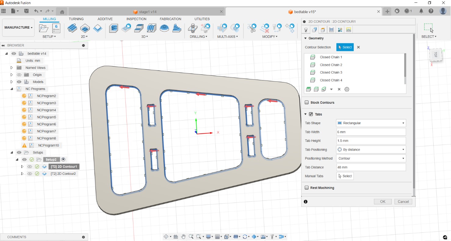 contour for internal parts
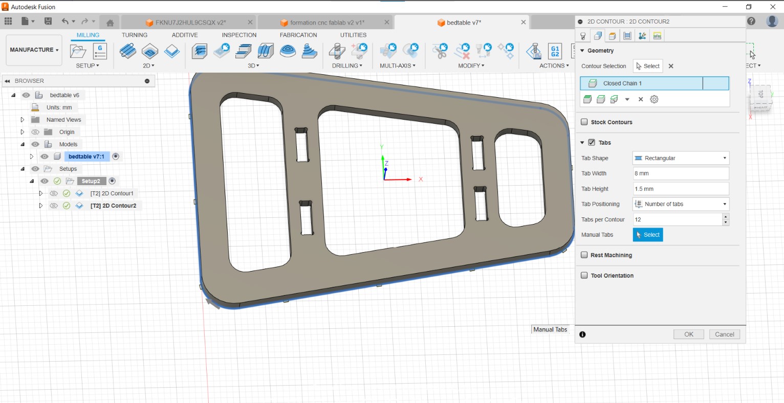 exterior contour of the part
Heights
In these window parameters, I have included a bottom height offset to ensure complete cutting of the material, especially in areas where the thickness may not uniformly measure 18mm.
Passes
The material is 18mm but ovisouly it will not be cut in one pass -> in this window parameter the number of passes are defined. I used the “multiple depths” option -> it will cut 3mm per pass -> 6 passes to cut the 18mm.
Linking In this window, I added a ramp, so the tool is not plunged directly in the material, but it will follow a ramp to go deeper and deeper.
Generated contours
The path a generated and are show on the software. You can see where the tool will enter in the material as well as where it will go out and the paths it will follow. You can you the simulation tool to see it in a dynamic way. It’s also possible to know the time needed for the machining.
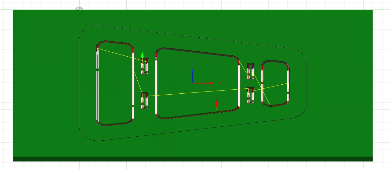 First contour
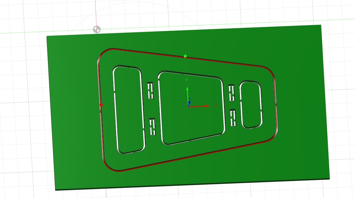 Second contour
Create the gcode
Select the setup to include all contours/tasks defined -> action -> post process -> choose post processor depending on the CNC machine -> choose a name -> post.
Check that the gcode is correct by checking the tool that are used, the height on the z axis, check the speed -> if it looks good -> let’s go on the machine
Step 3: prepare the CNC machine and the material
- Cut the wood plate to fit in the CNC machine
- Draw a cross on the material to know where is the origin that has been chosen during the gcode making
- screw the plate in the CNC machine (on the martyr) so it doesn’t move during the machining
Step 4: start the machining
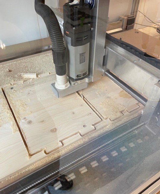
- Open KinetiC-NC ➔ homing so the machine knows its position
- Use the keyboard to put the tool over the origin position (origin is chosen during the making of the gcode and a cross can be drawn on the material to know where to put the tool)
- Do the zeroing of the machine for x, y and z (x,y by putting 0, z by using custom ➔ z position ➔ the tool will move down and touch the button place under it ➔ zero is done)
- Import the gcode file
- Check that all the paths are in the working area (if red zones ➔ not in the working area)
- Press play

Step 5: post process
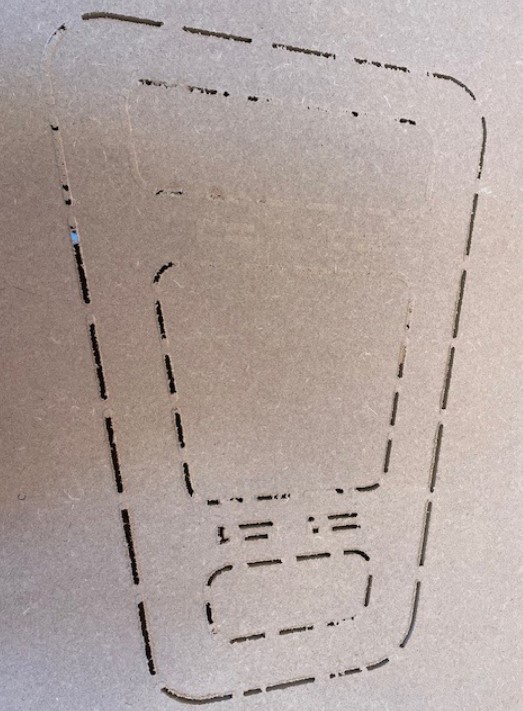
- Vacuum everything so it’s clean for the next use
- Unscrew the plate
- Remove the plate
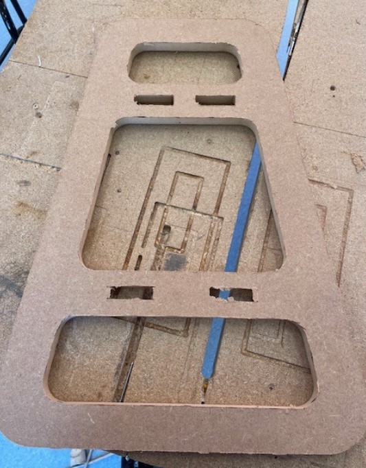
- Ready for the post processing !
Step 6: assembling
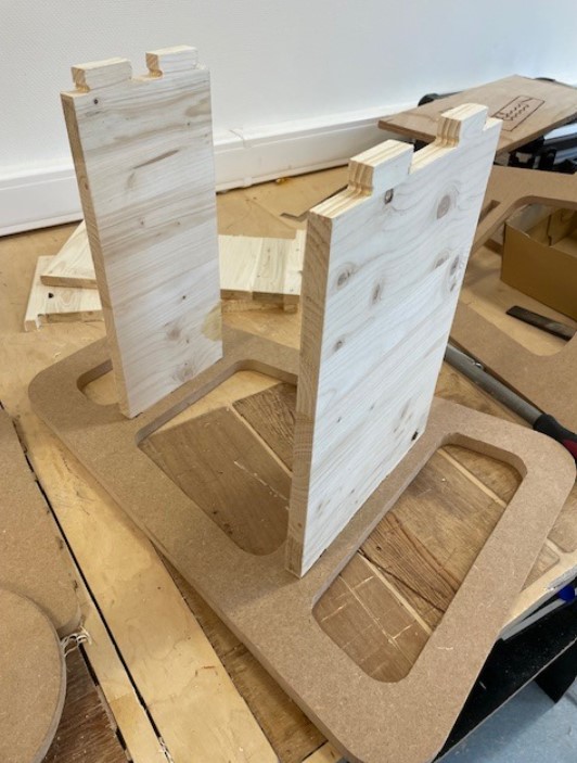
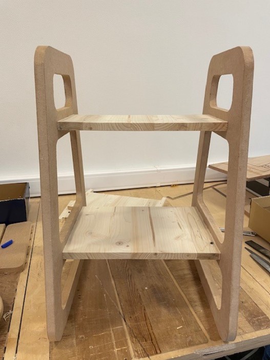
Final result

Shaper
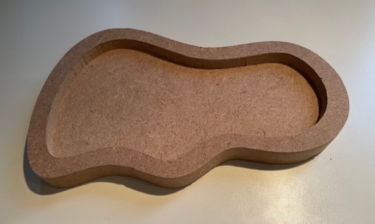
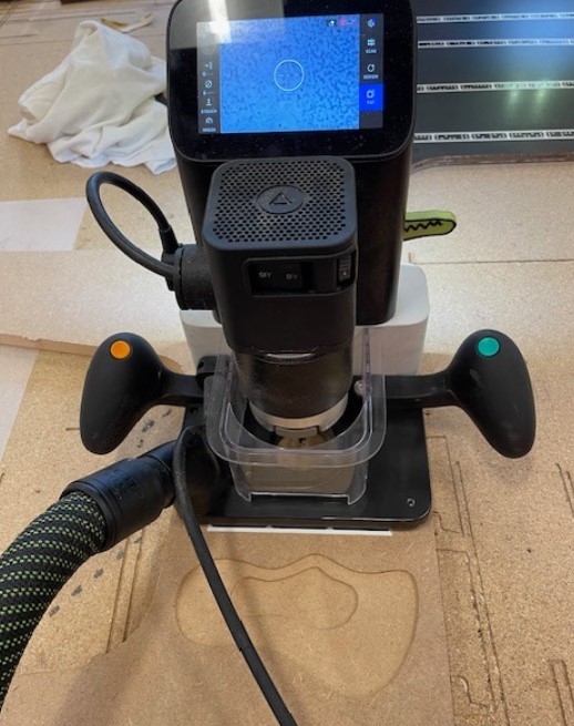
I wanted to try the shaper, which is a CNC machine that you guide with your hand, a bit like a video game. I did a basic and small stuff - a plate to put my rings on it on my bedtable !
I did the design on Fusion 360 as well. This time, it’s much more easier for the preparation of the gcode -> you just need the svg file of the parts, and the other parameters like the speed, the depth of cut and tool will be defined directly in the shaper machine.
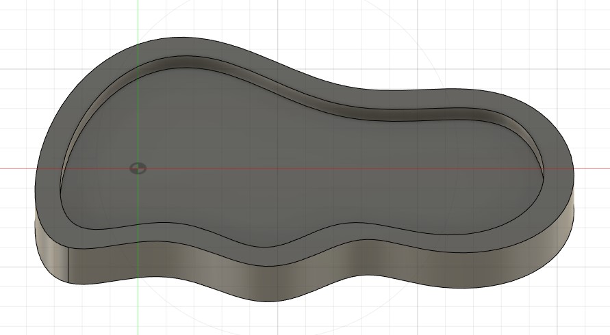
There is no direct export in svg file from fusion, but you can download the shaper add-in, that will help you do that ! Fusion app store -> shaper. As we can see below, you can select directly which face you want to export, and the plug in will create the svg file that can be use in the shaper.
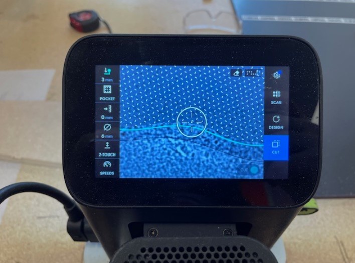
You put the svg file on a USB-key, put it on the shaper and let’s go select the parameters. Here I want to cut all around to cut my part but first I want to do a pocket in my piece. I will thus create different paths to follow with the shaper.
Design file
The design source files can be downloaded here.
Shaper preparation
- Fix the wood on the table so it doesn’t move during the milling - I used double sided tape between my wood and the martyr
- Put the tool on the machine - 6mm flat end
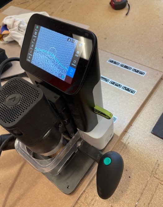
- Put the domino tape on your board, on the same height as where you will cut - the shaper camera uses this specific tape to do a calibration and to know where the machine is in the space
- Do the calibration -> scan -> move the machine all around to see the domino tape and record the work space
- Import the svg file -> cut -> select a line of the drawing -> pocket/contour -> crosses are displayed on the screen where you need to cut
- Ready to cut
Result
