Week 18: Applications and implications
Assignment
Propose a final project masterpiece that integrates the range of units covered.
I already described a lot in the different project pages (overview, test bench and prototypes), but I will do a summary here.
Context and description
| Questions that will be answered:
- What will it do? - Who's done that beforehand? |
Context
As part of my PhD, I’m working on the development of a pneumatic endoscope. A endoscope is a tube used in the medical field, in order to explore and threat the digestive tract.
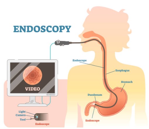
In order to navigate in the digestive tract, the tip of the endoscope is able to bend. This bending is usually actuated with cables, but in my thesis, the goal is to replace this actuation by a pneumatic one, meaning that the bending part of the endoscope is actuated thanks to 3 air chambers in which different pressures are applied.

What will it do ?
The goal of my project is divided into two parts:
- the fabrication of the pneumatic actuator prototypes
-
the design and development of a test bench able to characterize different pneumatic actuators
The test bench should be able to characterize some key parameteres of the actuators:
- The bending in terms of the function applied in the air chambers
- The force applied by the tip of the actuator
The test bench will be divided into different blocs:
- A pressure control board
- A mechanical modular structure to fix the pneumatic actuator
- A motion tracking system - i.e. camera to measure the bending angle of the pneumatic actuator
Who’s done that beforehand?
My project is really similar to soft robotics application, meaning that a lot of similar work have been done. I will list below the main articles or projects that have inspired me to create my owm test bench.
Inspiration
1) Gilles Decroly Fab Acamedy project
First of all, my thesis is the continuity of a previous PhD thesis made in my lab, by an alumni of the Fab Academy - Gilles Decroly. He also did a bench test to characterize the same kind of pneumatic actuators during his Fab Academy, so I spoke with him at the begining of my journey to point out the things that I could improve in his test bench. His test bench was directly inspired from the Soft Robotics Toolkit.
In the soft robotics toolkit control board, as well as in the Gilles’ project, the pressure control bloc is “homemade”: they used a constant air pressure source - an air pump (0-2bar)- and solenoid valves controlled with a microcontroller and Pulse Width Modulation (PWM) to regulate the pressure. Multiple issues were pointed out by Gilles with this method, but the main one being that the good control of the pressure is highly dependant of the quality of the components chosen, and that there are a lot of air losses in the system. At the end, he was not able to have a pressure above 1 bar. His main recommendation was then to pay attention to the components, mainly the valves, that I will choose.
In my project, i need to be able to provide a pressure between 0 to 3 bars, so the actuation bloc has been changed completely.
2) Articles of the litterature
Articles that helped for the prototyping part - mainly because it’s also pneumatic actuators used in medical field. It was usefull for understanding the challenges of making a good mold to produce the silicone actuator, as well as to see how to integrate the bending and force characterization.
- Design and Modularization of Multi-DoF Soft Robotic Actuators - Zhang
- An Origami-Based Soft Robotic Actuator for Upper Gastrointestinal Endoscopic Applications- Chaban
Inspiration for the pressure regulator block:
-
Towards a steerable multi-module soft robotic endoscope for NOTES applications - J. Lenssen
-
All-in-one automated microfluidics control system - C. Watson
-
Design and Control of Pneumatic Systems for Soft Robotics: A Simulation Approach - M. Xavier
Design, processes and fabrication
| Questions that will be answered:
- What will I design? - What materials and components will be used? Where will come from? - How much will they cost? - What parts and systems will be made? - What processes will be used? |
Design
The design part is divided into 3 parts: the design of the test bench itsfel, the design the control pressure bloc and design of the prototype. Each part will be explained below.
Test bench
For the test bench part, I first chose the different parameters that I wanted to characterize, so I know which components should be included in the test bench.
The test bench should be able to:
- Evaluate the bending angle of the pneumatic actuator -> need a tracking system as camera
- Evaluate the force developped by the tip of the endoscope -> need a force sensor (load cell)
- Monitor the pressure applied in the pneumatic actuator air chamber -> need a pressure sensor and a interface to show the pressure
- Be as modular as possible
Based on that, I designed the test bench and chose the components I need.
| Components | Made or buy | 3D design |
|---|---|---|
| Main structure: the structure on which will be fixed the pneumatic actuator, as well as the force sensor. It’s designed to be able to move the actuator fixture up and down thanks to the slot. It’s also designed to hide the background behind the pneumatic actuator, so the camera track just the pneumatic actuator and not some parasites on the background. |
Made by 3D printing |  |
| Aluminium extrusion: Some thin aluminium extruded stem will be used to attach the pneumatic actuator and the pressure sensor. | Bought | 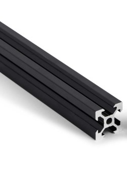 |
| Pneumatic actuator holder: it will hold the pneumatic actuator and be fixed on the aluminium stem. | Made by 3D printing | 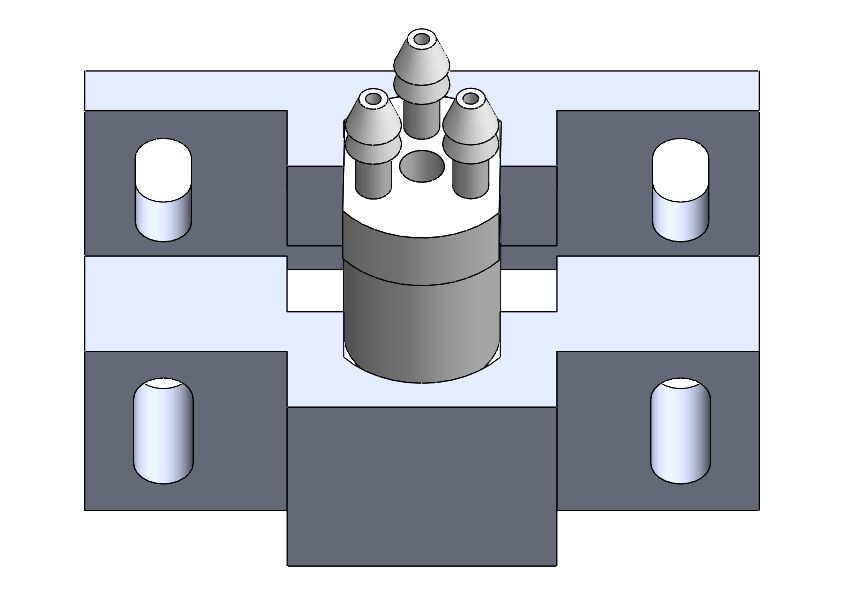 |
| Force sensor: it’s a load cell from Futek Sensor reference |
Bought - was available at my lab |  |
| Connector: used to connect the different components between them. | Made by 3D printing |  |
| Camera: for the bending tracking, I will use 3 cameras from OptiTrack. Camera reference |
Bought - was avaible at my lab |  |
| Solid aluminium plate: a solid aluminium plate on which the main structure will be fixed, as well as the camera. The plate comes from Thorelabs: reference |
Bought - was available at my lab | 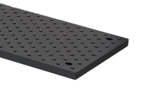 |
| Camera holders: 2 kinds of camera holders: - one for fixing and orienting the camera in high: the pieces are laser cut and assembled to create a arm camera holder. - another to place the camera on the test bench: 3D printed. |
Made by laser cutting and 3D printing |  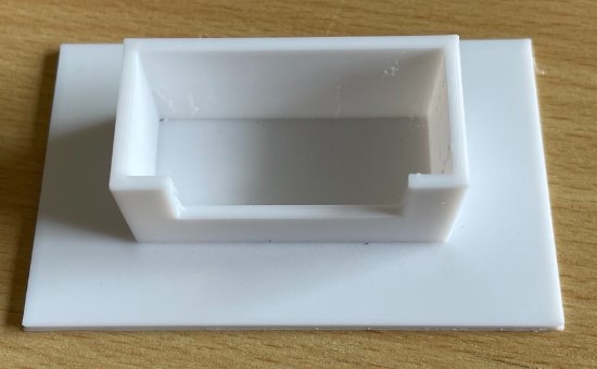 |
Pressure control bloc
For the pressure control bloc, my goal was to have a pressure control more robust that what is made in the litterature, based on the advices of Gilles (see above). I also have some requirements to meet that have dicted the choice of my components.
Requirements:
- Have 3 independant control channel
- Regulate the pressure between 0 to 3 bar
- Have a precision of at least 0.1 bar
- Be able to control the pressure with my computer
Compare to Gille’s project, the idea was then to improve the range of pression and also the precision. To do so, I decided to choose industrial pressure regulator (available in the commerce) to replace his idea of controlling solenoid valve with PWM. The pressure regulators that I chose also incorporates valves, but their control is already handled. Instead of control directly the valve, I will thus control the pressure regulators with analogic signals ranging from 0 to 10V.
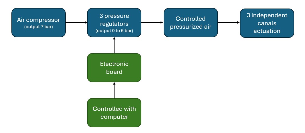
The diagram below summarizes the operating principle of my pressure regulator block. It’s obviously simpler than in other articles, since I don’t deal directly with valve control. It works as follows: a compressor delivering air at a pressure of 7 bar is connected to 3 independent pressure regulators. The pressure regulators regulate the pressure between 0 and 6 bar, and must be controlled by analog signals from 0 to 10V. To achieve this, the pressure regulators are connected to an electronic board which transforms digital signals received by the computer into analog signals using a dac (digital to analog converter).
| Components | Made or buy | Design |
|---|---|---|
| Compressor | Bought - available at my lab | |
| Pressure regulators: VPPE model from Festo. It’s based on a proportionnal valve actuation. Reference |
Bought |  |
| Electronic board | Made by PCB milling + soldering |  |
| Elecronic box | Made by 3d printing and laser cutting |  |
Prototype
The pneumatic actuator prototyping is also a part of my final project, as I want to improve they are made, and I also want to test multiple dimensions and air chamber shapes.
For the prototyping part, I need to make molds in which I will pour silicone to create the actuator. It’s also an important part of my project because the test bench will be used to test not one kind of pneumatic actuator but variation of them:
- Multiple air chambers diameters and shapes
- Multiple pneumatic actuator lengths and diameters
- Multiple rigidity of silicone
The molds will thus be adapted for the different pneumatic actuator, and different problematic will be adressed (for example it’s easier to make mold for a bigger actuator diameter than a smaller one).
| Pneumatic actuator diameter | Pneumatic actuator length | Air chambers diameter | Central lumen diameter | Rigidity |
|---|---|---|---|---|
| 15 mm | 70 mm | 3 mm | 4 mm | Shore hardness 10A, 20A, 30A |
| 9 mm | 80 mm | 1.5 mm | 3 mm | Shore hardness 10A |
| Components | Made or buy | Design |
|---|---|---|
| Silicone tube | Made - silicone molding |  |
| Air supply connector | Made - SLA printing |  |
Process that have been used during the project
- 3D printing (FDM, SLA & PolyJet)
- Laser cutting
- Molding
- PCB milling
- Soldering
Bil Of Materials (BOM)
Below you can find the BOM of the different parts of my project. There is some price that have been estimated as the material was available at my lab and thus not bought.
Test bench
Pressure control bloc
Prototypes
Validation and evaluation
| Questions that will be answered:
- What questions need to be answered? - How will it be evaluated? |
To evaluate if the project was a success, I should be able to:
- Actuate multiples pneumatic actuators with different shapes and dimensions:
- The pneuylatic actuators must be changed easily
- The actuation should be possible in all directions
- Actuation should be controlled by a computer
- Track the tip of the pneumatic actuator and determine the bending angle
- Track the force applied by the tip of the actuator