Week 12: Input devices
Assignment
Individual assignment: Measure something: add a sensor to a microcontroller board that you have designed and read it
Group assignment: Probe an input device’s analog levels and digital signals -> see group assignment
What I did
I used a I2C pressure sensor with the board that I designed during week 8.
Pressure sensor
For my final project, I’d like to have an interface that shows the pressure in my pressure chambers in real time. To do this, I’m going to use a pressure sensor that I’ll be testing this week. I will test the sensor with the board that I did in week 8, which was designed to be able to link other sensors to it.
The pressure sensor is a ASDX from Honeywell, the datasheet can be found here, as well as this one for the I2C communication. I will use this sensor this week because it was available at my fablab, but it can only measure a pressure up to 1 bar, which will be too low for my final application, so I will try to get another sensor with a higher pressure range for my final project.
I2C communication
I2C (Inter-Integrated Circuit) communication is a serial communication used to connect electronic devices together on the same circuit board or over a short-distance network. The I2C bus allow to create an electronic communication between multiple different components thanks to only 2 wires:
- SDA = Serial Data Line -> used for the data transfer: data will be transfer bit to bit on that line.
- SCL = Serial Clock Line -> used for the clock signal, i.e. for synchronization of the data transfer.
In I2C a “master” or “controller” communicate with a “slave” or “peripherial”. The data between the two are transferred in messages that are composed of multiple information: a frame that containtes the address that specifies the binary address of the peripherial, and other frames that contains the data that must be transferred. There is also a start condition to switch the state of the SDA line from a high voltage to a low one, and a stop condition that does the opposite. A read/write bit is also used to specify whether the controller is sending data to the peripherial (low voltage level) or requesting data from it. Finally, a ACK/NACK bit that follows every frame of message to acknowledge the reception of the frame.

Note master/slave vocabulary was previsously used and is now replaced by controller/peripherial vocabulary.
Note documentation about I2C: link 1 and link 2.
Communication test
I wanted to use MicroPython for the code, so I followed the tutorial here to know how to use MicroPython on Visual studio code. First step is to download the MicroPico extension. Then:
- Create a folder where to put the code
- Open it with visual studio code
- CTRL+SHIFT+P -> and choose “MicroPico: Configure project”
- It will add 2 files in the folder: one “.vsocde” and one “.micropico”
- Connect the board while pressing bootsel button and flash the MircoPython firmware on the board: a file open, and the firmware should be past in it. here is the one for the RP Pi Pico W board. -> when connected correctly, the “Pico connected” information is written on the bottom of the visual studio window
- Create a python file in the folder and write the code
I first tested the communication between my board and the pressure sensor, by following this tutorial. It explains how to do a I2C communication between a raspberry pi pico board, i.e. the microcontroller that I have on the PCB that I designed on week 8, and a I2C sensor.
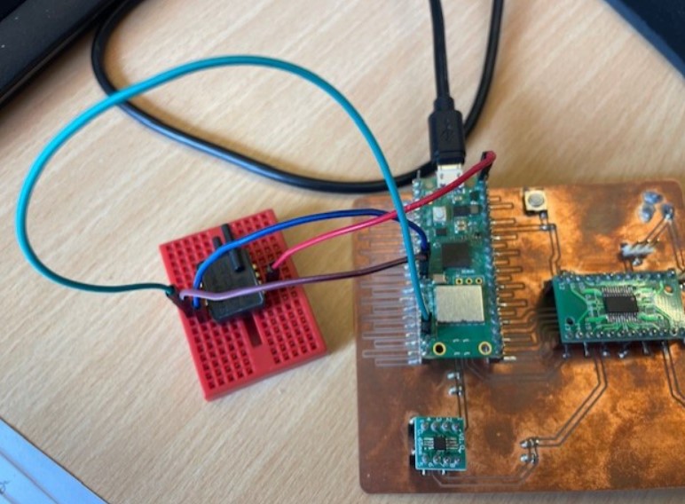
Sensor connection
I checked the datasheet for the sensor connection:

- Pin 1 SDA pressure sensor -> GP8 - SDA pin of the board
- Pin 2 SCL pressure sensor -> GP9 - SCL pin of the board
- Pin 3 - GND -> GND of the board
- Pin 4: Not connected
- Pin 5: Not connected
- Pin 6: Vsupply -> VBUS of the board - 5V alim
- Pin 7: Not connected
- Pin 8: Not connected
Code
I took the example code from the tutorial to test the connection of my sensor:
import machine
import utime
sda = machine.Pin(8)
scl = machine.Pin(9)
# I2C initialization
i2c = machine.I2C(0, scl=scl, sda=sda, freq=400000)
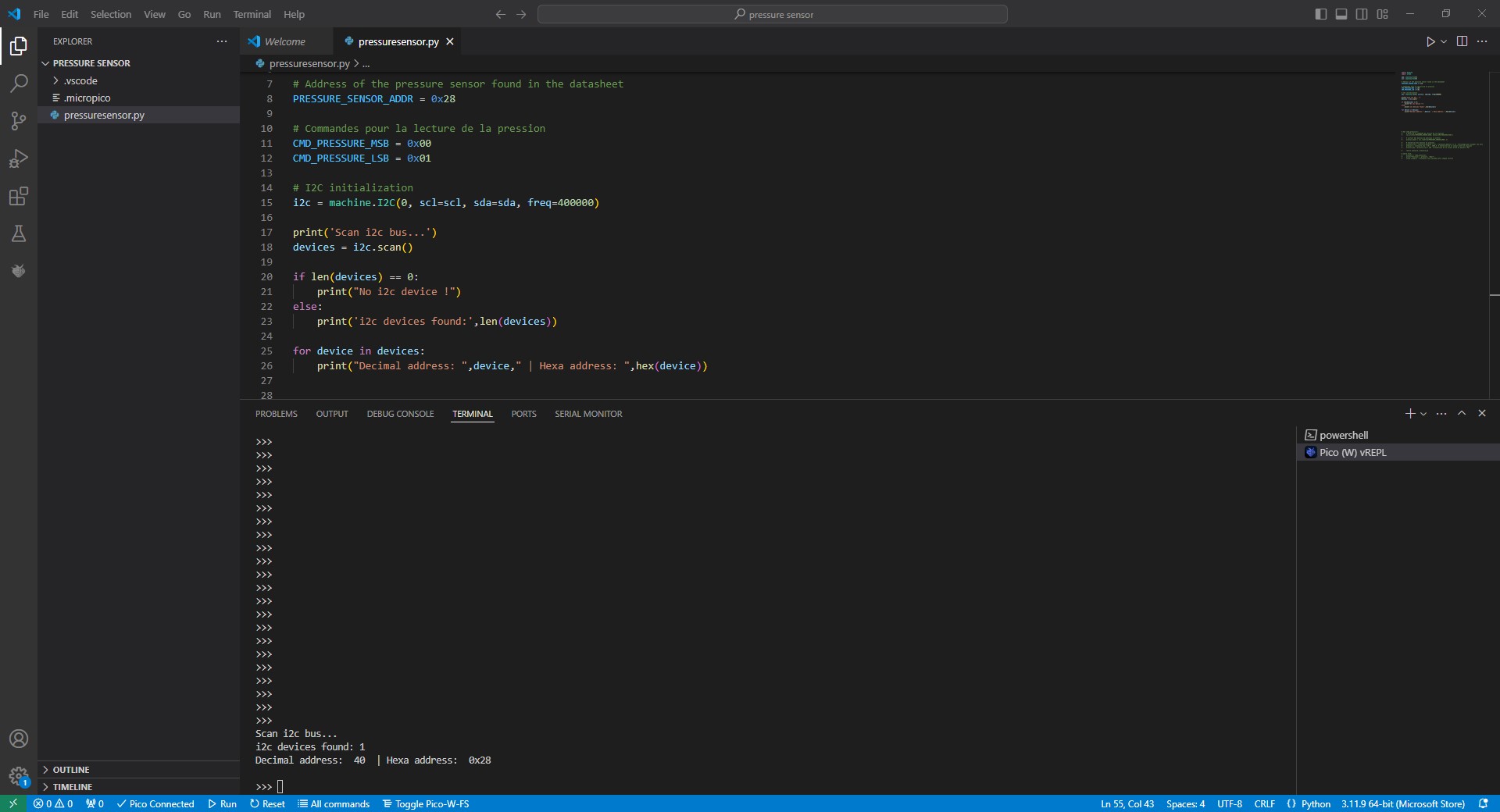
print('Scan i2c bus...')
devices = i2c.scan()
if len(devices) == 0:
print("No i2c device !")
else:
print('i2c devices found:',len(devices))
for device in devices:
print("Decimal address: ",device," | Hexa address: ",hex(device))
Results
It’s ok, my sensor is recognized by my board.
Measuring pressure
Now that the connection is ok, I can do the code to read the pressure with the sensor. To do so, I used this documentation about I2C communication function in MycroPython. I also used the datasheet here, to know how to compute the pressure with a Honeywell pressure sensor based on the digital outputs sent by the sensor.
Function to calculate pressure:
On the datasheet, the following equation is given to compute the pressure based on the output of the sensor:
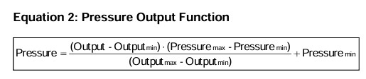
I thus create the same function in my code, and defined all the parameters:
# Defined values specific to sensor
min_output = 1638 # given in datasheet
max_output = 14745 # given in datasheet
min_pressure_psi = 0.0  # min pressure (psi)
max_pressure_psi = 15.0  # max pressure (psi)

def calculate_pressure(compensated_pressure_output, min_output, max_output, min_pressure, max_pressure):
    pressure_psi = min_pressure + ((max_pressure - min_pressure) * (compensated_pressure_output - min_output)) / (max_output - min_output)
    return pressure_psi
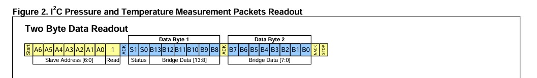
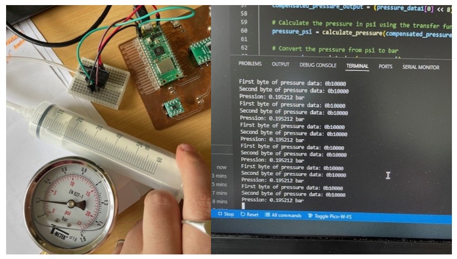
The compensated_pressure_output is the value that I need to read from the sensor. To do so, I used the documentation above to know how to read from the sensor, and how to process it in order to used it in the pressure calculation. The sensor will send the pressure informations on 2 bytes, as shown in picture below. In the code, it means that I will first read the first byte, then the second one and combine the 2 bytes to obtain the pressure output. It’s done as followed:
def read_pressure():
# Read the first byte of data
pressure_data1 = i2c.readfrom(PRESSURE_SENSOR_ADDR, 1)
i2c.writeto(PRESSURE_SENSOR_ADDR, b'\x00', True) # Acknowledge the receipt of the byte
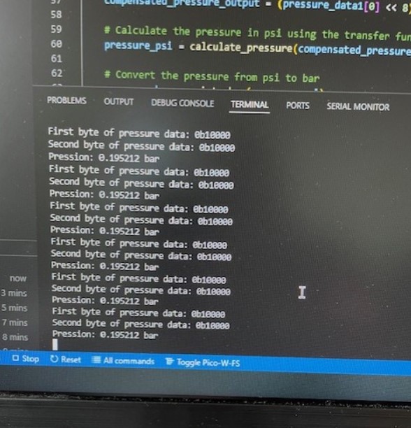
print("First byte of pressure data:", bin(pressure_data1[0]))
# Read the second byte of data
pressure_data2 = i2c.readfrom(PRESSURE_SENSOR_ADDR, 1)
i2c.writeto(PRESSURE_SENSOR_ADDR, b'\x00', False) # Acknowledge the receipt of the byte
print("Second byte of pressure data:", bin(pressure_data2[0]))
# Generate NACK and stop condition
i2c.writeto(PRESSURE_SENSOR_ADDR, b'', True)
# Combine the two bytes to get the compensated pressure output
compensated_pressure_output = (pressure_data1[0] << 8) | pressure_data2[0]
Code file
The code file can be found Here
Results
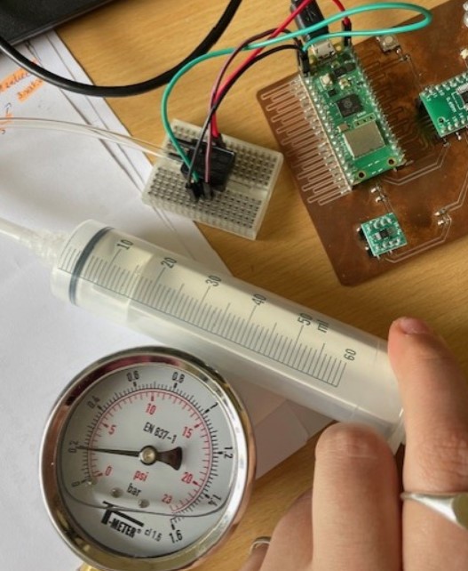
To know if the pressure that I’m reading with the sensor is correct, I used a manometer. As we can see, the manometer shows a pressure of 0.2 bar, and the pressure sensor 0.195212 bar. I could change the number of digits of the pressure results according to the sensor precision.
Update week 14
You can go and have a look on my week 14 if you want more details about I2C communication and differences from SPI communication.
Update week 16
I add some details about I2C communication on this page.