Prototypes
Pneumatic actuator
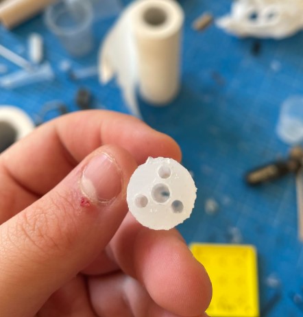
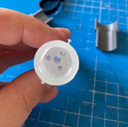
The pneumatic actuator consist in a silicone tube, in which 3 air chambers are embedded for the bending control, as well as a central lumen in order to insert tools or camera inside the actuator. The different manufacturing steps, are summarized below.
Molding and casting
Week 13: making a mold to manufacture the pneumatic actuators
I used the molding and casting week to develop a mold aimed to produce the silicone pneumatic actuators that will be characterized with the test bench developped for my final project. I made 6 different actuators, with 3 different silicone rigidity and 2 types of pneumatic chamber shape.

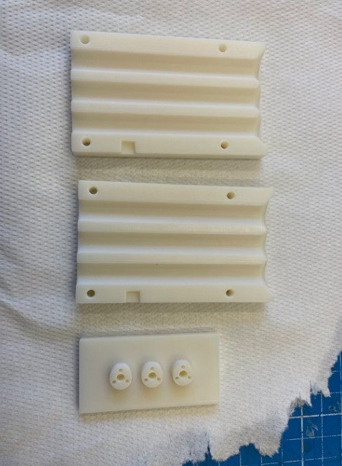
The mold can be seen below, and the details of design and conception are explained in the week 13. The mold is divided in 3 main parts to ease the demolding part, and 3d printed rods that are inserted in the base of the mold to create the air chambers and central lumen.

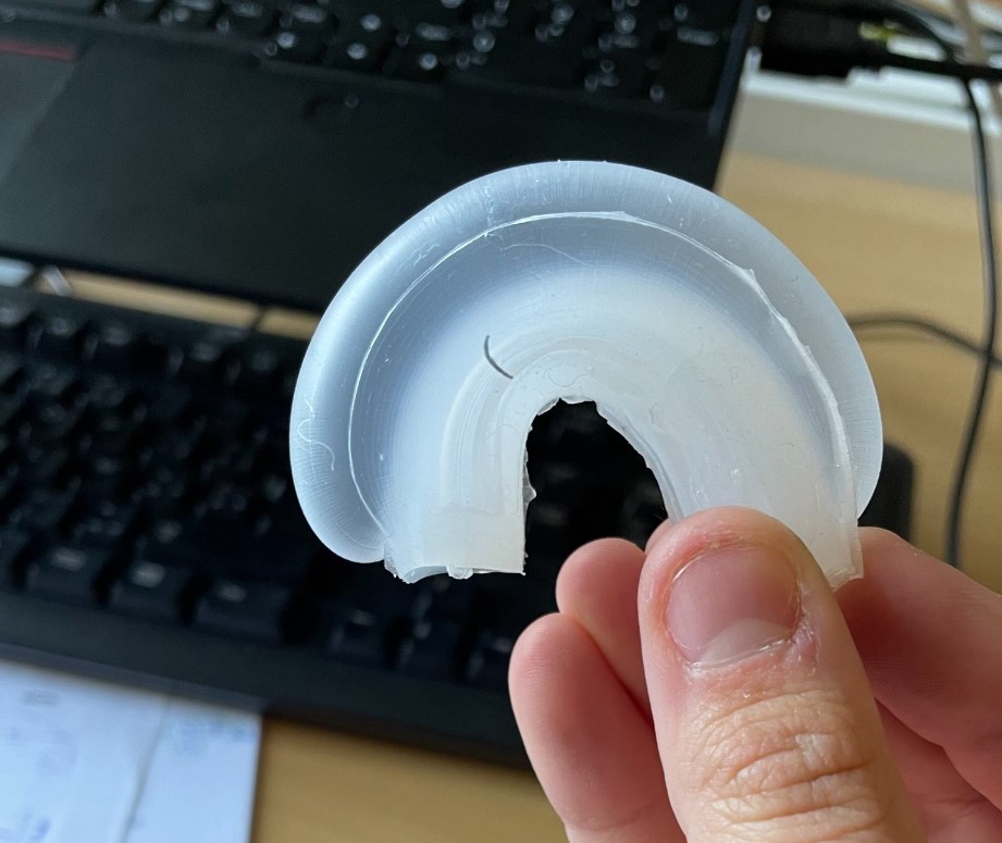
Here is the pneumatic actuators that I obtained after the casting
Week 13 to the end
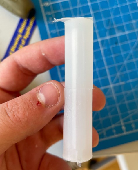
I continued to work on the molding part of the project as I needed to produce pneumatic actuators with new dimensions: this time they are thinner and longer than the previous ones. It brings new challenges for the molding part:
- With long and thin cavities, bubbles are easily trapped when the silicon is poured in the mold
- Due to the smaller actuator diameter, the air chambers diameter should be reduced too -> it’s more difficult to print very thin and long rods AND to keep them well aligned
-> Multiple steps of mold prototyping has been followed to find a good solution -> see week 13 for the details of the iteration process
Here you can see the final mold that has been used: it has been 3D printed in resin with a Stratasys Eden 260v, it’s a polyjet printer.
Connection to air supply
Week 5: 3D print of a pneumatic connector
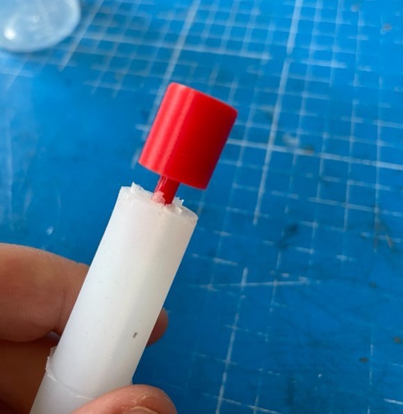
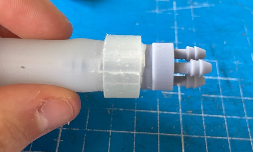
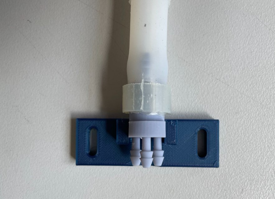
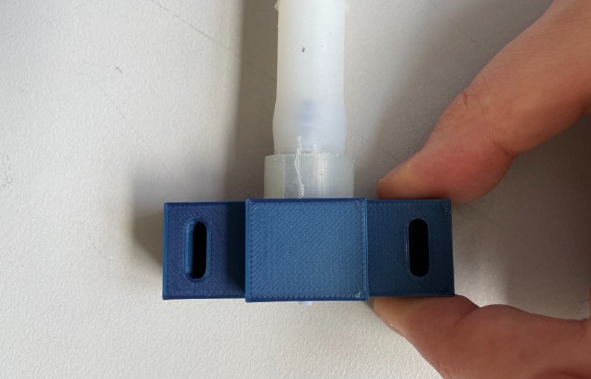
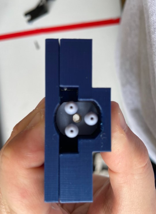
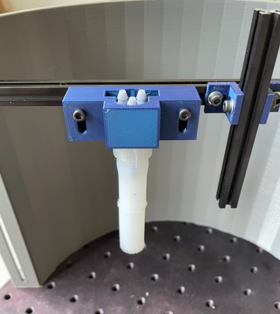
In order to connect the pneumatic actuator to an air supply system without air losses, I designed during week 5 a connector that is inserted in the pneumatic actuator and have 3 others pneumatic connector for the air supply. I 3D printed it with an SLA printer during week 5 as well. the design has also been developed so that the actuator can be easily mounted in the test bench, thanks to its slightly flattened part, as can be seen on the picture below.

The steps below described how to connect the pneumatic connector and the pneumatic actuator.
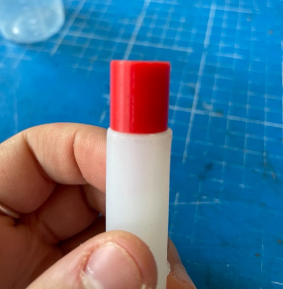
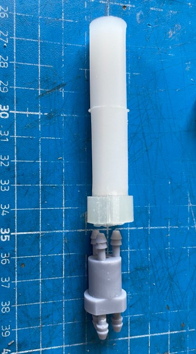
Then the actuator can be fixed in the test bench, and changed easily to test different actuators.
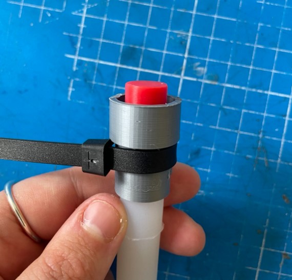
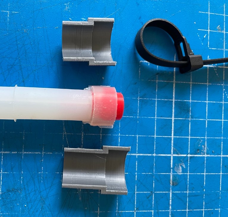
Anti-ballooning structure
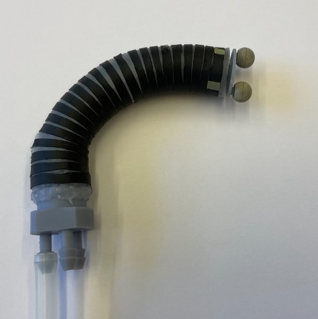
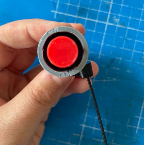
When pressurized, the air chamber not only bend the pneumatic actuator, but they also inflate. To avoid this phenomenon, a heat shrink tube can be cut off in multiple pieces and dispose around the actuator. When heated, they will be attached on the actuator and will prevent the balloning effect.
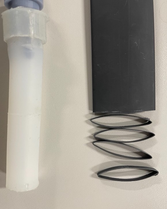
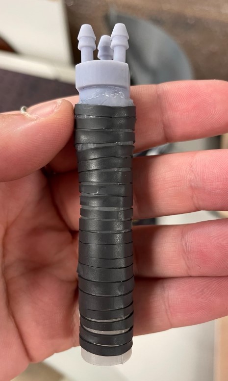
Before and after: