Week 2: Computer aided design (CAD)
The goal of this week is to model (raster, vector, 2D, 3D, render, animate, simulate, …) a possible final project. I will thus design the mechanical structure of my test bench, which I described in week 1.
CAD tools
-
I have already some 3D design skills using Solidworks and Creo. For this week assignment, I will start with Solidworks, and then try some other softwares if I have enough time. I would like to try FreeCAD as it is an open source software.
-
In terms of 2D software, I will give a try with GIMP in order to develop a schematic on how the force sensor will be measuring the force at the tip of the actuator.
Solidworks - Mechanical structure
The mechanical structure will be mainly divided into 2 parts:
- one to hold the endoscopic actuator and the force sensor;
- one to hold the camera used for the tracking motion.
Both parts should be modular in order to be able to move the different components in the test bench without being blocked.
It is composed of:
| Component | 3D design |
|---|---|
| Main part: it is designed in order to hide the background, so that no objects of the background will be detected by the camera as a marker, which could induce some errors in the flexion angle computing. |  |
| Flat aluminium extrusion: this part will be the main support on which the force sensor and the endoscopic actuator will be fixed. Thanks to the slot in it and in the main part, every parts can be moved easily and the test bench is therefore modular. These parts have not been designed by me, I have downloaded the CAD design on the MISUMI website. |
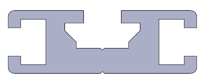  |
| Connection: used to connect the different components between them. | 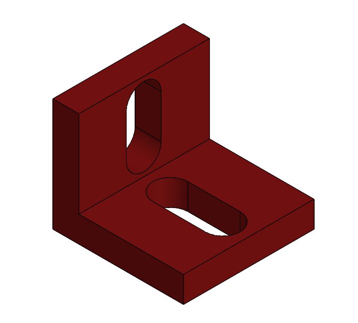 |
| Endoscopic holder | 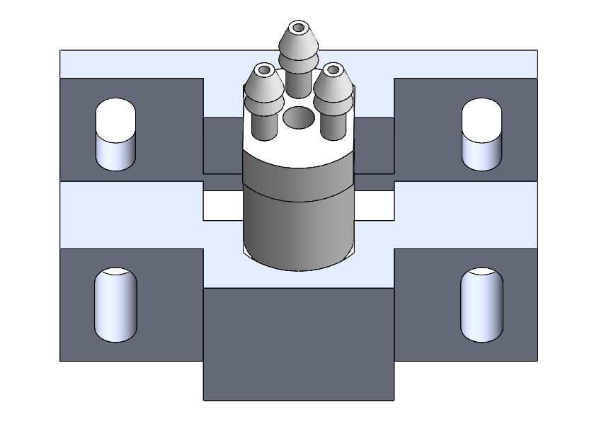 |
| Force sensor: the 3D design of the force sensor have been obtain on the Futek commercial site | 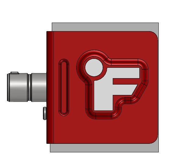 |
Each part have been designed separately and then I have created an assembly to obtain the full test bench that is shown below.
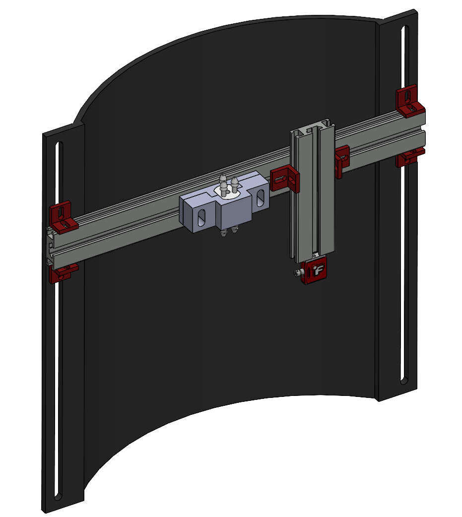
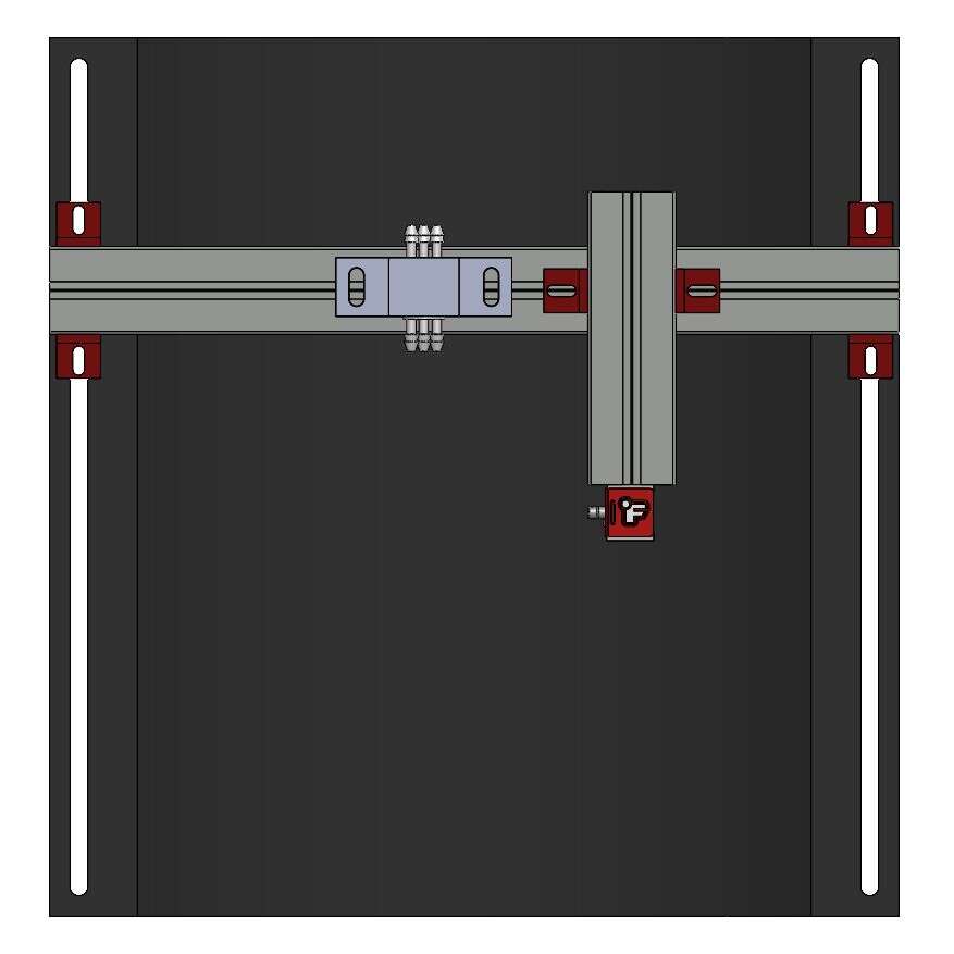
Mechanical structure holding the endoscopic actuator and the force sensor
An assembly is quite usefull to make sure that every parts will fit together correctly before printing them or buying them. On Solidworks, it can be created like a part (file -> new -> assembly), and then you insert parts that are already existing in your files or create one directly in the assembly. I always prefer not to create parts directly in the assembly.
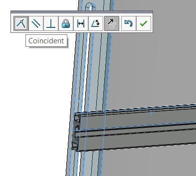
You can link the different parts that you add in the assembly by putting some mates between them. For example here, I wanted the aluminium part in contact with the main structural part, so I add a “coincident mate”.
The Solidworks source files can be downloaded here.
FreeCAD - Endoscopic actuator design
I had a little more time this week so I decided to try to use FreeCAD for a basic design, to try a new 3D design software.
I had already designed my endoscopic actuator with Solidworks earlier during my PhD, but I needed to add a new channel that was not present in the initial design, so I did it with FreeCAD.
I have used the Basic Sketcher Tutorial that allowed me to start quickly. I first created a new part, and I have select the “Part Design Workbench”, which gives me access to the sketch option to create my part.
-
Create a circle

-
Fix the radius length: right click on the circle in the element panel -> radius -> fix the length & a name
-
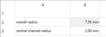
I have fix the value of the radius in a spreadsheet: Spreadsheet workbench -> new spreadsheet -> overall-radius & its value -> right click on the value -> properties -> alias (overallradius) -> back in the sketch -> value of the radius -> select the spreadsheet alias that I just gave.

-
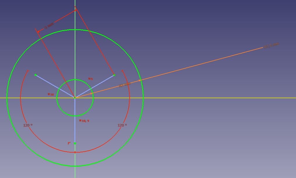
I have construct some “construction lines” and put some constraints on them so they have the same length and separated by a 120° angle.
-
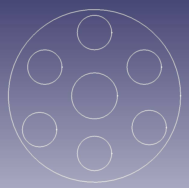
I have add circles that are centred at the end of my construction lines
-
I have a final sketch that can be extruded with the “pad” option
 , still in the “Part Design Workbench”.

The FreeCAD source files can be downloaded here.
GIMP - Force measurement
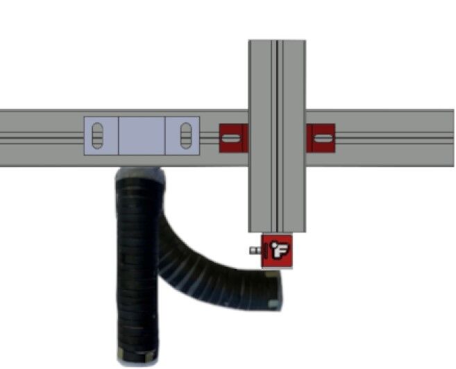
I wanted to have a nice illustration on how the force sensor and the tip of the endoscopic actuator will interect between them. To do so, I have used GIMP.
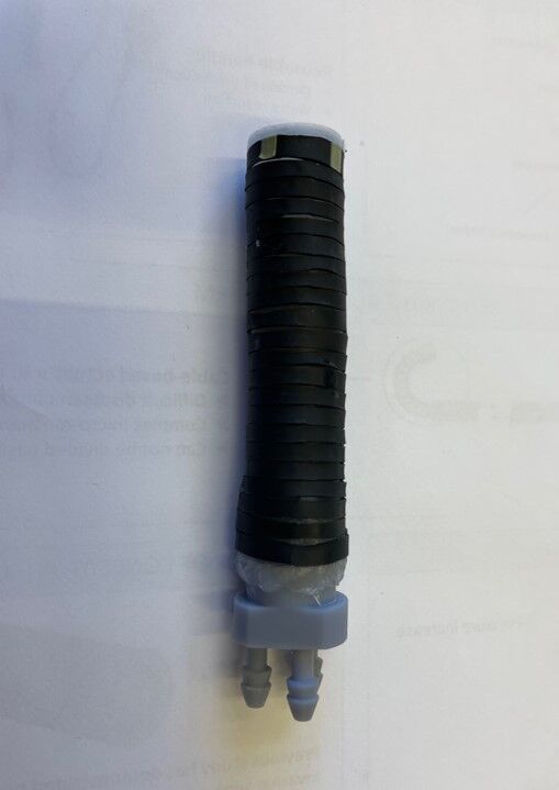
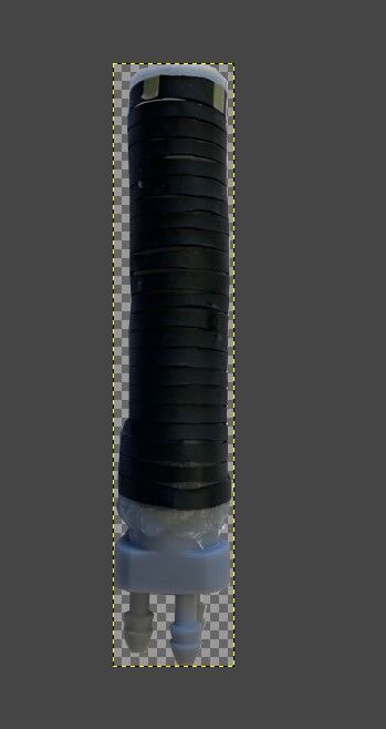
- Free hand selection tool: I used it to cut the actuator from the background of the image. It’s done by selecting manually multiple points all around the object.
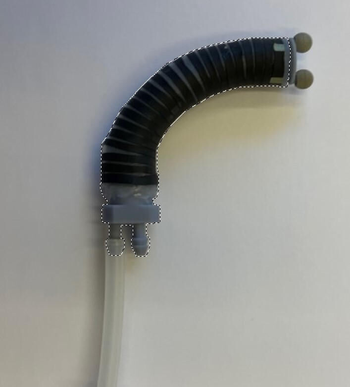
- Fill the font with a withe color
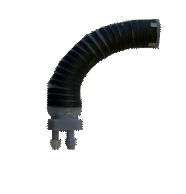
- I did the same with the actuator in a rest position
-
Scale and rotation tool: just used this 2 basic tools to superpose my 2 cut objects one on the other with the same size and orientation
-
I added a picture of some parts of the test bench, including the force sensor, and I remove the background as well in order to past this on the same image as the actuator.
I end up with a image with my actuator in rest and bend position, as well as the force sensor and a part of the test bench, that will be anotated to explain how the interaction between the tip of the actuator and the force sensor works.
Compressing images
During the course, Neil explained to us the necessity to have small size image in our website in order to not overload the server but also to have a fast website, with no difficulty to load every big image. To do so, “.jpeg” file are more compact than the “.png”. However, I realized that I only had “.png” pictures. I thus wanted to use the tool that Neil showed during the course called ImageMagick, and that allows to manipulate digitale images. I will thus described how I used it to convert all my “.png” pictures to “.jpeg” all at once.
I started by downloading the software for windows by using the tutorial given on the website. I have downloaded the zip, and followed the instruction of the README file.
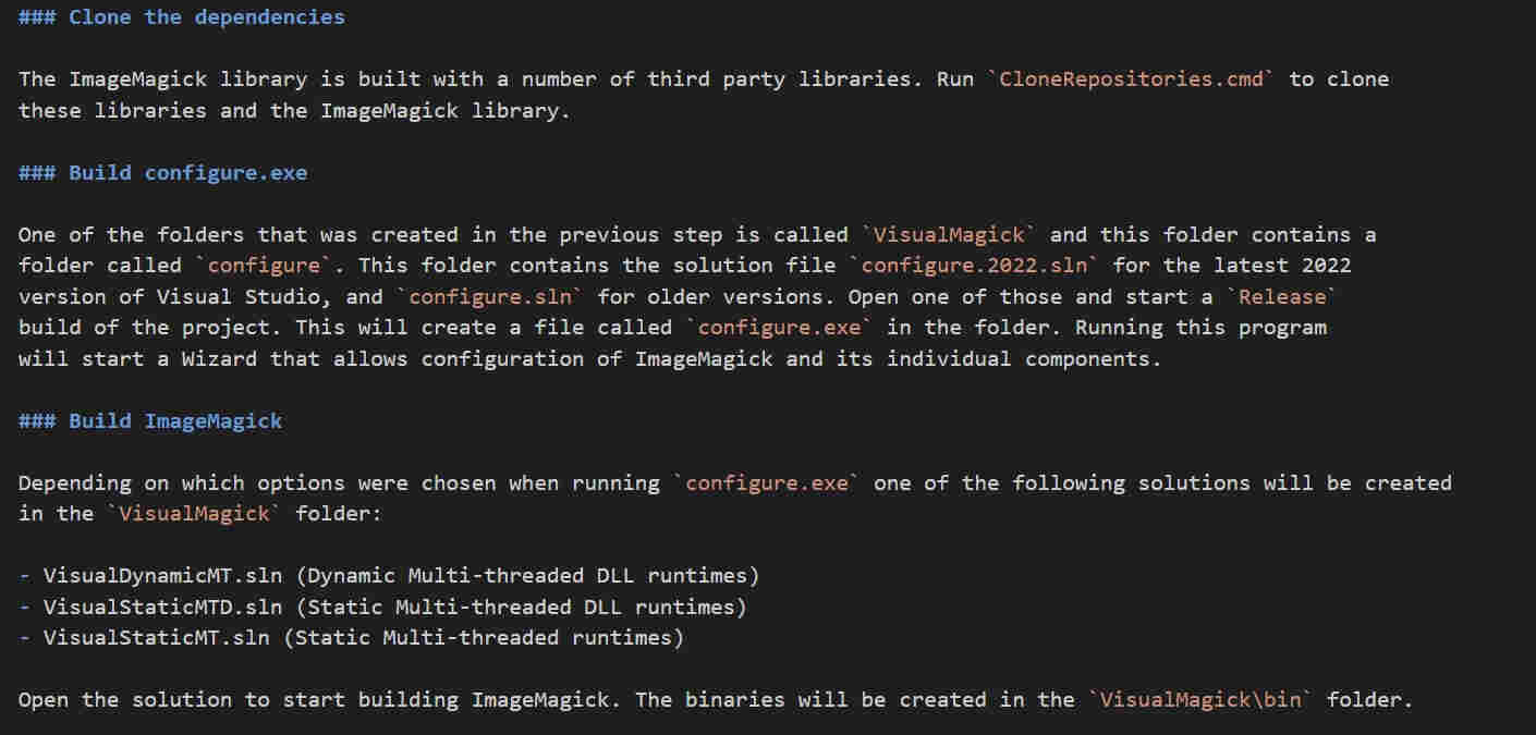
At this point, I’ve got some problem to manage to download ImageMagick, because of the “Build configure.exe” step that was not working. I talked with one of my collegue that is also doing the fab academy, Teo. He just downloaded the windows executable file from this page, and then it works, you can use the different commands in a terminal.
The following command can be used to modify the “.png” file to “.jpeg” file and also to change the quality to have smaller size images.
magick mogrify -format jpg -quality 80% -path ./jpeg *.png
The command if you just want to reduce the size of one image:
magick name.jpg -quality 80% name.jpg
Update after global review - vector 2D modelling
During week 2, I only used GIMP as you can see above, but I didn’t used any vector modelling stuff. However, during the next weeks of Fab Academy, I used Inkscape multiple times and I used the vectorization tool. For example I used Inkscape a lot in week 3, where I used it to vectorize my different FreeCad designed parts, to cut it with a laser cutter. All the steps to vectorize the image from a “.dxf” file is explained on the week 3 web page. I also
Advantages of a vector based images
Vector images are images expressed by mathematical formulas which is interesting because the image’s size can thus be changed without losing image quality even if the resolution changes. On the contrary, raster images, that are made of square pixels, will loose quality with change in image’s size.
As explained in week 3, Inkscape can be used to create vectorized images, by saving the images in a “svg” file, which means “Scalable Vector Graphics”. Other softwares can be used as well, as Adobe Illustrator or even PowerPoint.