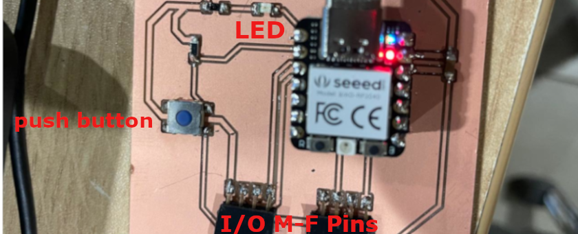
I select to do something similar to the PBC develop by Adrian Torres and use Module XIAO RP2040 as a starting point to fabricate
a basic board to interact and communicate with a push bottom and a LED. And thinking on my final
projet I added 8 pins that could act in future as Inputs or Outputs. The electronic components
included are listed as follow:
01 Seeed Studio Xiao RP2040.
01 1kΩ resistor
01 499 Ω resistor
01 LED 1206
01 SW - Button >
01 Female horizontal row header
01 100 μf capacitor
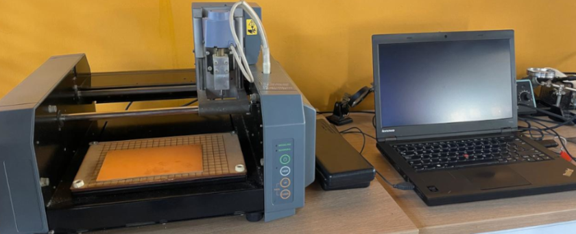
PCB and CNC Machine Setting
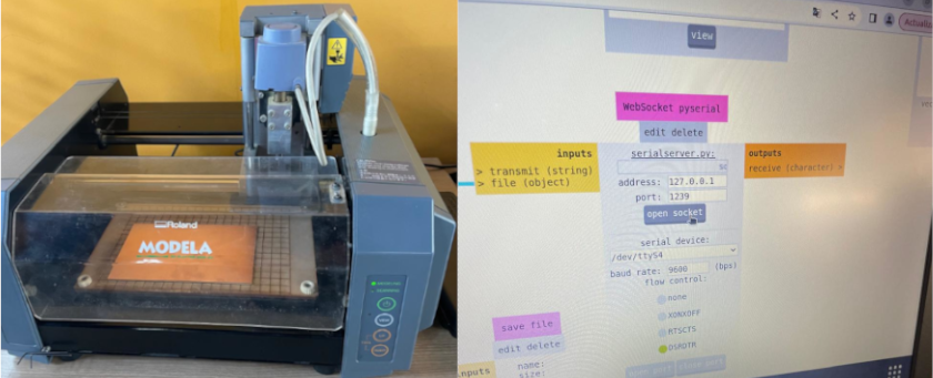
The machining was made with a Modela MDX-20 in two parts. First traces using 1/64¨ y secondly cutting
the edges using 1/32¨ end mills.
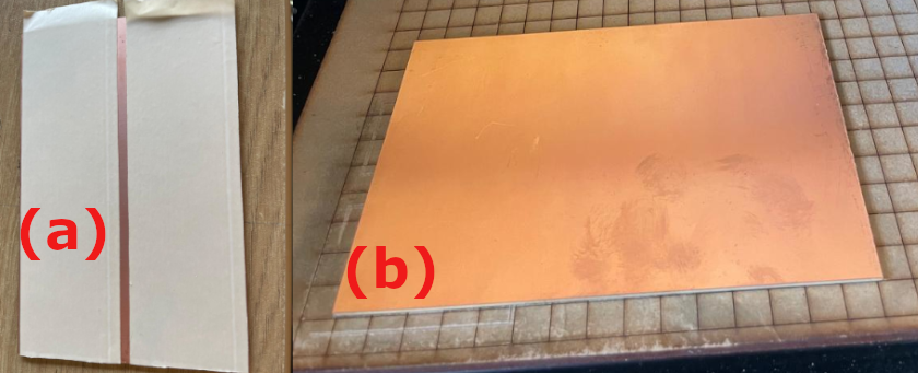
We need a FR1 PCB board in this case we have available Copper Clad - Double Sided 4x6in. To set
and mill it on the CNC machine we proceed as follow:
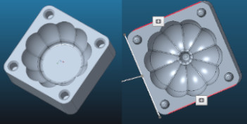
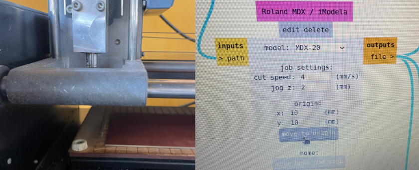
Set double-sided tape into one side of the PCB (See fig a)
Hold the FR1 board with double-sided tape into the machine, to avoid loosing the end-mill
we set the PCB on X-Y plane orientation, starting at (10,10) coordinates (See fig b).
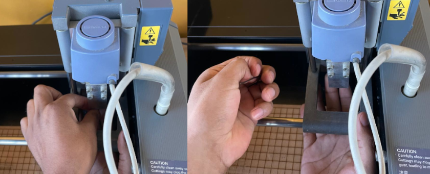
Set power-off to introduce the end-mill, use a Hex Key to free the Grub Screw
In this case for Paths you need to use a 1/64". It is recommendable to introduce 2/3 endmill's
length into the machine endmill holder, to avoid failures and broke the endmill.
We need to open the FabModules Sotfware, this module work with linux, thus we work with a laptop
that only contain that system.
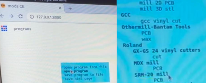
OpenMods CE Software.
Click Open Program that will appear listed on a light blue window.
Look for Roland Brand and Select MDX mill PCBthat will appear listed
down Roland machine.
On the CNC press view bottom, the end mill will move to (o,o) coordinates
Then we need to move the endmill to the PCB origin (10,10) using FabModules
I proceeded with the zero calibration on the z-axis, to do that the machine has two bottoms.
" UP" and "DOWN" , you've need to hold the down bottom, and the endmill will drill down faster
and stop when your are near to the PCB
Then, you need to press down bottom little by little, the endmill will drill down slower, until
you'll see that the endmill release some cooper
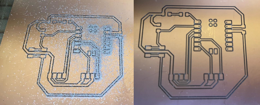
The following photo shows the final result after milling traces
Yopu repeat this process with the 1/32" endmill to cut the PCB
This video shows the 1/64" milling process (traces)
This video shows the 1/32" milling process (cutting)
PCB Soldering
It was my first time soldering, so I didn't remove the double contact tape, and used to
attach the PCB to the Soldering Mat Silicone (Heat Resistant), trying to avoid any movement
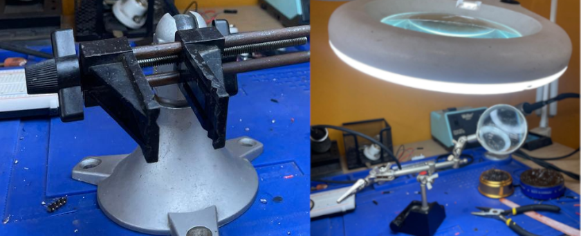
while soldering. However it is recommendable to use the following soldering accesories to
better handle the process
Helping Hand with Magnifying Glass
Electronic Work Center
Magnifying Glass Soldering Stand with LED light
For the soldering process my instructor suggest me to star with smaller componebts
I started soldering the resistors and LED
The strategy was to fix one side (pin) of each component and then the others
To proceed, first we can heat the PCB on the pin's area and deposit a small amount of
soldering wire
Then, took the component with a soldering tong and heat the area again
The first side would be attched, and then easily you could do the other side, without using
soldering tongs
The following video shows the soldering process
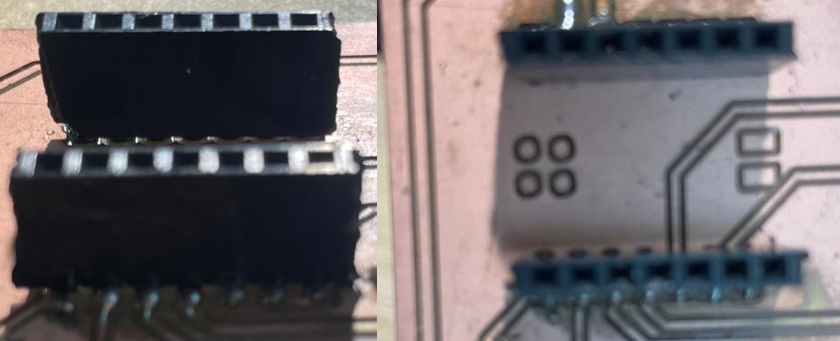
Then, I soldered the buttomand the pin headers.
Here I must highlight that the seed estudio XIAO RP2040 require to solder pin headers, to
being able
to attached to the PCB. I soldered 2 1x7 M-M vertical pin headers to each side
Within the PCB I soldered 2 1x7 F-M vertical pin headers at each side to receive the XIAO
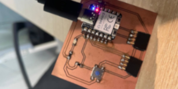
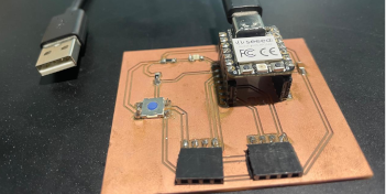
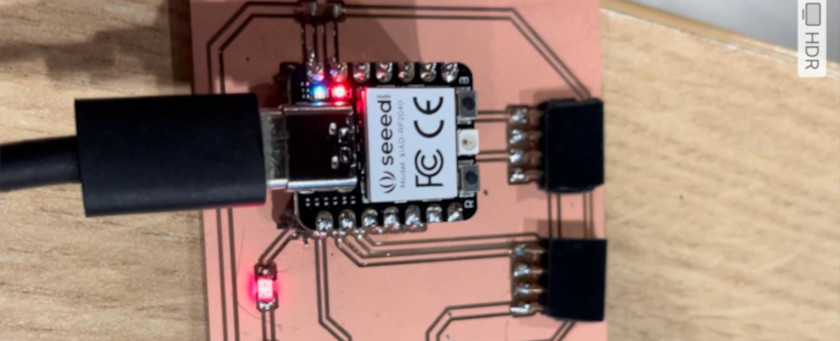
The following photo shows the final PCB soldered result
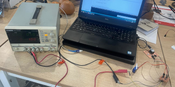
PCB Testing
The testing process was undertake in two steps:
First PBC testing with the multimeter aim to look for potential problems with the soldering
process. Here we ensure that only ground traces produced sound during testing
The funtioning test was made with basic programing using ArduinoIDE. To do that we need
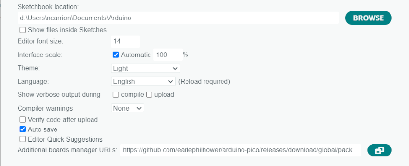
first to prepare the Arduino IDE to work with XIAO RP2040
We need to add Seeed Studio XIAO RP2040 board package to Arduino IDE's preferences (See
photo).
Like recomended on Seeed Studio
installing earlephilhower package.
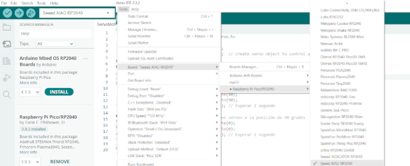
We need to go to Board Manager and install Raspberry Pi Pico/RP2040.
Then, we need to click on Tools, boardboard manager.
In that way Arduino IDE will recognise the XIAO RP2040
We need to wrote a small program in Arduino to test the board. I decided to develop a simple
program
to turn LED on and off, but using push buttom.
I use chat GPT to get a basic coding using the following prompt: "could you provide me a code to
use it on arduino IDE that allows me to control a LED with a push buttom using a XIAO RP2040 as
a control board"
	// Define pin numbers
	const int buttonPin = D1; // the number of the pushbutton pin
	const int ledPin =  D0;  // the number of the LED pin

	// Variables will change:
	int buttonState = 0; // variable for reading the pushbutton status

	void setup() {
	  // Initialize the LED pin as an output:
	  pinMode(ledPin, OUTPUT);
	  // Initialize the pushbutton pin as an input with internal pull-up resistor:
	  pinMode(buttonPin, INPUT_PULLUP);
	}

	void loop() {
	  // Read the state of the pushbutton value:
	  buttonState = digitalRead(buttonPin);

	  // Check if the pushbutton is pressed.
	  // If it is, the buttonState is LOW:
	  if (buttonState == LOW) {
		// Turn LED on:
		digitalWrite(ledPin, HIGH);
	  } else {
		// Turn LED off:
		digitalWrite(ledPin, LOW);
	  }
	}
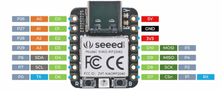
At the begining the "const int buttonPin = D1" assign the number of the pushbutton pin and the
"const int ledPin = D0" define the number of the LED pin. This assign correspond to the following
Pinout
The "void setup" is a function that contains the initialization of the two components that I want
to control (input=Push Button and output=LED)
"pin mode", will configure the pin DO to behave either as an ouput (LED) and D1 as an input (Push
Buttom)
"void loop" allows to repeat your code over and over again, that is why we need to add here the
"buttonState = digitalRead(buttonPin)" (input D1)
Then, we need will set a HIGH or a LOW value to output digital pin, in this case pin DO (LED
Connection). Because the pin has been configured as an OUTPUT with pinMode(),its voltage was
set to receiving 5V - 3.3V, being in HIGH mode (turn LED on) when the buttom is not pushed
(buttonState == LOW)
And it will receive 0V (ground) being in LOW mode (turn LED off) when the buttom is pushed
(buttonState == HIGH)
We need to upload the codeinto the XIAO RP2040 by clicking upload buttom
on Arduino IDE, the program will be upload on XIAO RP2040
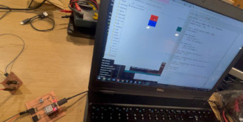
Then, we just need to tried if the program runs, like shown in the folowing video
run the program and check for LED lightining like shown in the video below
The following video shows how the led goes on and on when pushing the buttom

 The following video shows how the led goes on and on when pushing the buttom