W18: Project Development
Final Project: Motorized Hidden Pop Up Shelf

Final Project: Motorized Hidden Pop Up Shelf

Complete your final project tracking your progress:
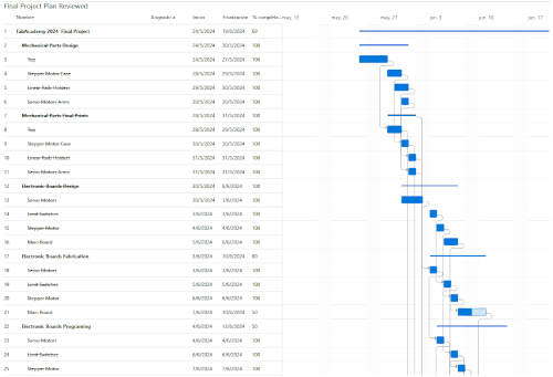
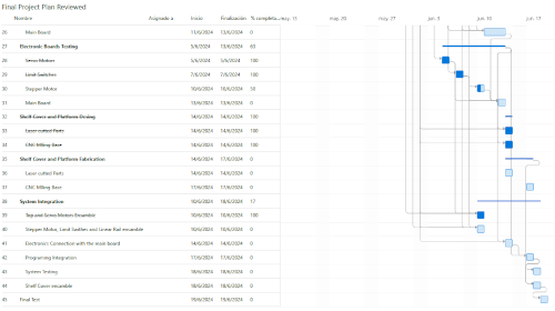
The presentation day is approaching, and various of the planned activities have been completed. I have progress with the mechanical parts and electronics, testing individually the pherifericals functioning. However, the integration to test shelf's functionality, it the challeging part. Then Gantt shows the progress achieved.
I donwload the files to printed them, and to have an idea about dimensions. Because I need to test the diferent funko models, not every model present same characteristics. So I can decide if I could used packed or unpacked funkos. I have some problems when printing. i think that it was because my filament was expose to much time to humity.
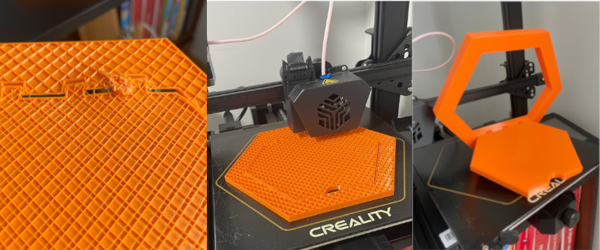
I test product dimensions using different kind of funkos, because some special design are wider or taller. So I can decide for which kind of funkos I will develop my final design. I also notice that build something for the unpacked funkos will need something bigger

Base on testings I started the desing of the mobile top using Fusino 360. At the begining I made mistakes with 3D printing tolerances and the I couldn´t get a mobile desing like show in the photo bellow
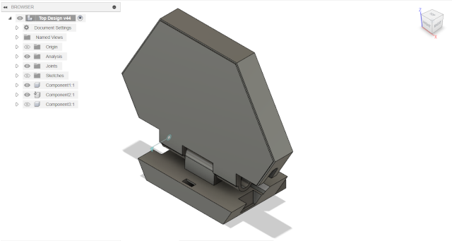
I redesigned the top and I've got a mobile desing and 3D printed it, like show in the following photos
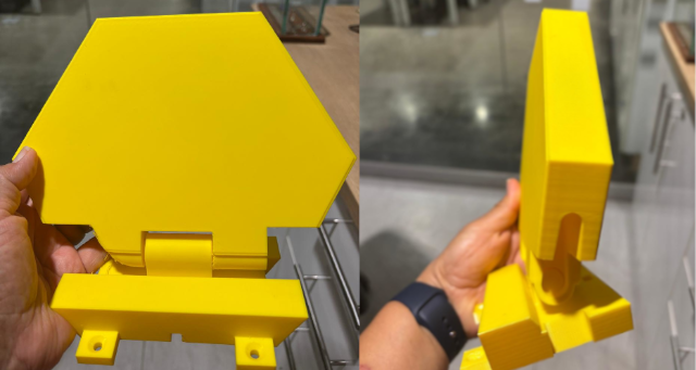
I also designed the Stepper Motor case like show in the following photos
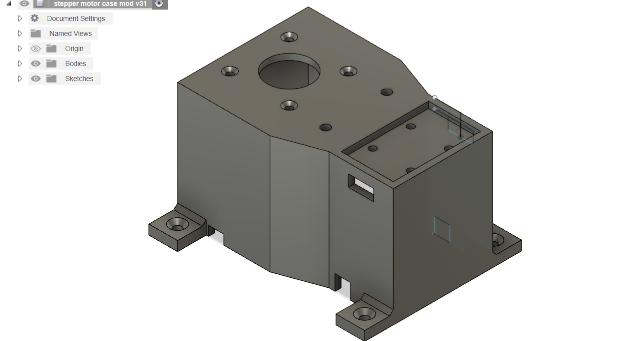
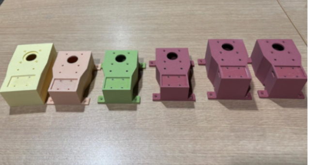
I've have to make several trials, due to dimensions that I did not consider at the begining,and that also to include to rectancular holes to incorporate the limit switches. But at the end, the final changes were made due to its high, because it need to be aligned with the mobile top. Like it can be observed in the following photo.
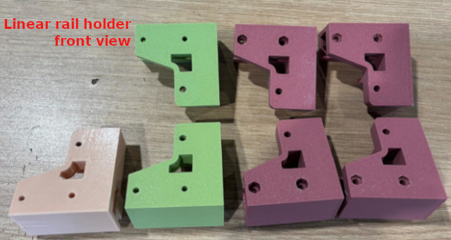
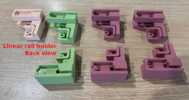
The third mechanical components are the pair of the linear rail's belt holders. I have made several trials, mostly because I need to adequately place the hexs. You can see the different changes in the following photos that show front and back views of the holders.
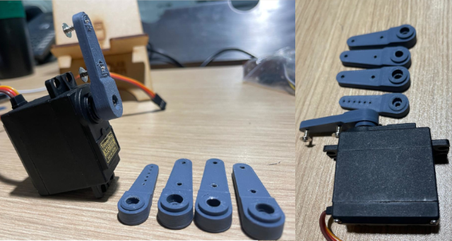
The final mechanical part are the pair of servo motors arms, because commercial design does not fit my design. I have made five trials due to length and width details, to adequately fit the servo and the top cavities.
With my instructor support, we review the components that I'm gonna need for my final project in
order to decide which output could be the starting point. So I decide to start with a Servo
motor that I'll probably use to open the hidden shelve. The following picture show the potential
devices that I would use for my final project. I would use 2 Servo Motors, so the option could
be to fabricate one or two boards. The initial idea was to use a switch or a remote control to
control prototype motionI decide to fabricate one. However, I after analysing the motion system
I need to include more limit switches. Thus my pherifericals would be:
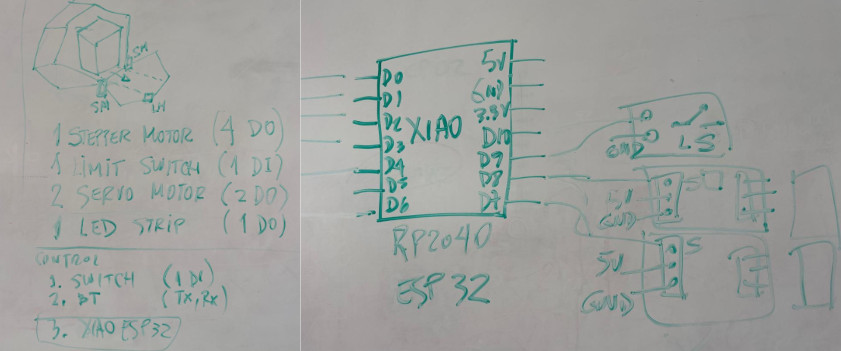
On week 9, with my instructor support, we review the components that I'm gonna need for my final project in order to decide which output could be the starting point. So I decide to start with a Servo motor that I'll probably use to open the hidden shelve. The following picture show the potential devices that I would use for my final project. I would use 2 Servo Motors, so the option could be tofabricate one or two boards. I decide to fabricate one.
 By
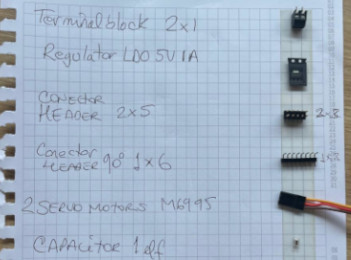
acknowledging that servo motors function with 5V and common power supply sources provide 12V, we
select the following components for this main board. It consists of the following:
This is the pcb design where you can see all the components. You can download design file and
the SVG files here.
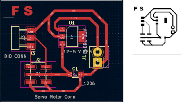
I proceeded with machining and soldering the PCB board
 For
functional
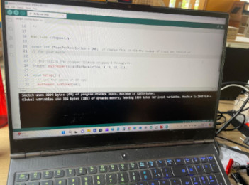
testing I used a modified coding provided by
Adrian-Torres
The following photo shows all system connection to test. I used XIAO RP2040 from Week 8 to test
the
board and the output device (Servomotor) 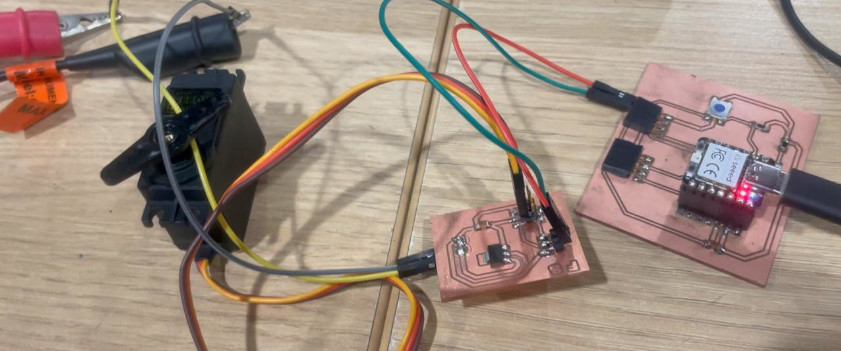
The final test was made runing the conding Arduino IDE and using a variable energy source, like shown in the following video
On week 12, with my instructor support, we review the components that I'm gonna need for my final project in order to select input device. The only input is a limit switch, that is going to activate all the complete system to stop the stepper motor that will show the funko. The following picture show the potential devices that I would use for my final project.
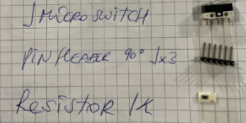 By
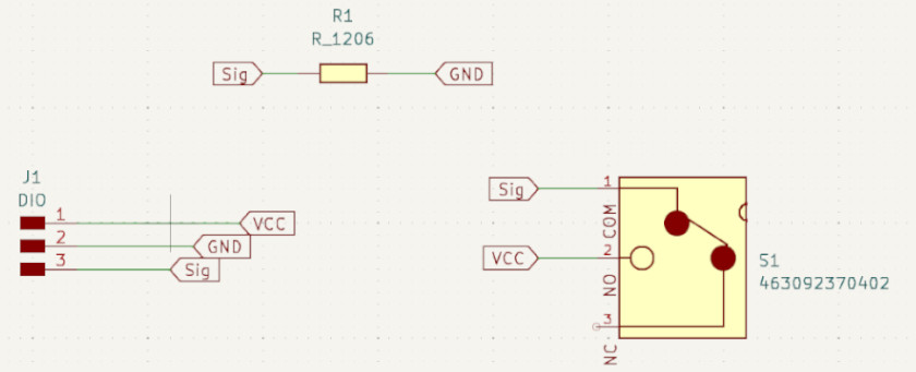
acknowledging that switch function we select the following components for this main board:
This is the schematic where you can see all the components. You can download Schematic design
file
and the PNG file here.
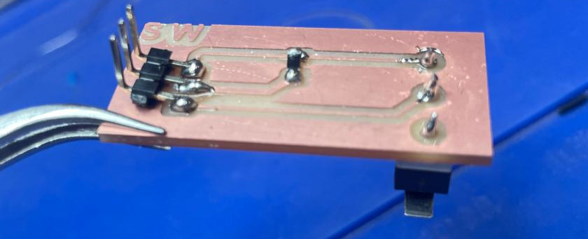
This is the pcb design where you can see all the components. You can download design file and
the SVG files here.

The final PCB image is shown below
The following photo shows all system connection to test. I used XIAO RP2040 from Week 8 to test
the
board and the output device (Servomotor) 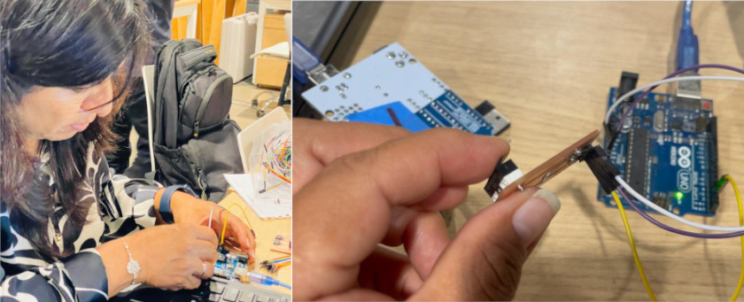
On 14th week, with my instructor support, we review the components that I'm gonna need for my final project in order to decide which could require a wifi or bluethooth communication. So I decide to start with a Servo motor that I'll intent to use for opening the hidden shelve. The following picture show the potential devices that I would use for my final project. I would use 2 Servo Motors, so I decide to execute a bluethooth connection, using an app to activate the servomotor.
 I
used
the board design and fabricated at
week 9 ,the following are its components:
This is the pcb design where you can see all the components. You can download design file and
the SVG files here.

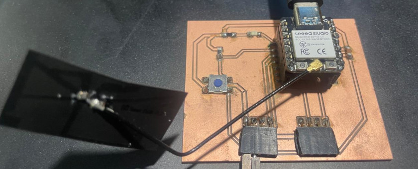
I used the board design and fabricated at week 8 , because its design includes a push bottom and a LED, and have DIO pins to connect the servo motor controller, and replaced the XIAO RP"=$= by XIAO ESP32C3. The following are its components:
This is the pcb fabricated where you can see all the components. You can download design file and
the SVG files here.
First I decide to test the microcontroller following the steps suggested by Seeedstudio here. and use the LightBlue App to control my servomotor
In the following images you can observe the process
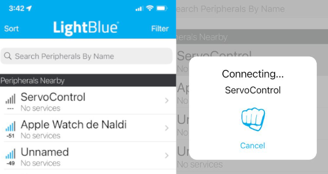

You can download the Bluetooth code using Arduino IDEhere.
In the following video you can observe the final result when controlling the ServoMotor
On week 15, we first generated a code for a 180 arm movement. The code will need to recognize the serial imput that will come from the computer interface to control a microservo SG90
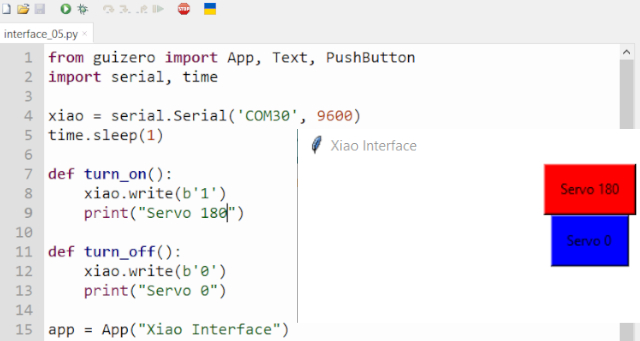
You can download the Arduino Ide and Thonny Programing files here.
In the follorwing video you can observe the final result when controlling the ServoMotor
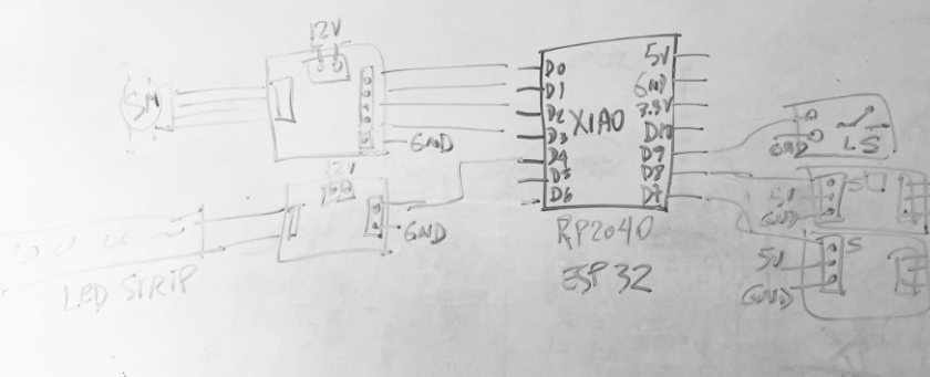
I have two options to develop my final project's main board, that does not change its general structure, but its interface to activate it.
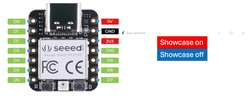
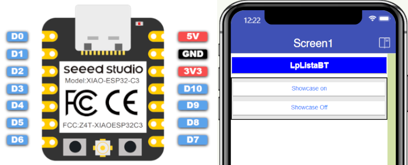 Its advantage it is not only wireless control, but anyone that could use also LightBlue
and
introduce a string-value
to activate it.
After reviewing the mechanical and electronics requierements for my final project, I elaborate
its schema integration that is shown in the following image.

Thus, I would proceed to analyse system integration within mechanical design that I've already
develop for the project
All the mechanical parts fail at the begining, and I had to modify them as follow:
The following pictures shows the progress I have achieved until now

The things I need to resolved are the following:
Once the servo motors programing would be resolved, I need to start with all electronic integration and joint all programs. Thus, I would generate a flow chart to better understand the communication between inputs and outputs
Then I will need to test the integrated programing, but I will need to integrate a 12V poower source and a XL4015 5A Voltage and Current regulator, that would provide adequate energy for the electronic components
After, I will be able to test the system, and when it runs I would fix every component to the Shelf's base and then place the shelf's cover
After all the achived progress, I have learn that: