9th week Assignment
Output Devices
Output Devices
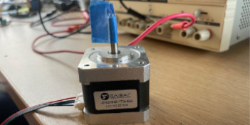
First, it is neccesary to notice that exist different output devices. I found something very useful that help me understand at Lydia Kuo - Fab Academy 2023 Web Page. We decided to test a stepper motor functioning process considering that my classmate and I will use this device for our final projects.
 In our case we
choose to test a step motor available at FabAcademy Inventory and because it is considered a digital
input-output device. A stepper motor (sometimes referred to as a step motor or stepping motor). This
product offer a shaft motion consists of discrete angular movements of
essentially uniform magnitude when driven from a sequentially switched DC power supply, such being
describe at Electromate.com . It works with digital signals. One digital pulse to a step
motor drive or translator causes the motor to increment one precise angle of motion. As the digital
pulses increase in frequency, the step movement changes into continuous rotation. So we can test it at
full motion. It has windings in the stator and permanent magnets attached to the rotor. It provides
fixed mechanical increments of motion (referred as steps, and generally specified in degrees). They are
considered ideal for applications that require quick positioning over a short distance, Allowing the use
of an open-loop controller, which simplifies machine design and lowers cost compared to servo motor
systems.
In our case we
choose to test a step motor available at FabAcademy Inventory and because it is considered a digital
input-output device. A stepper motor (sometimes referred to as a step motor or stepping motor). This
product offer a shaft motion consists of discrete angular movements of
essentially uniform magnitude when driven from a sequentially switched DC power supply, such being
describe at Electromate.com . It works with digital signals. One digital pulse to a step
motor drive or translator causes the motor to increment one precise angle of motion. As the digital
pulses increase in frequency, the step movement changes into continuous rotation. So we can test it at
full motion. It has windings in the stator and permanent magnets attached to the rotor. It provides
fixed mechanical increments of motion (referred as steps, and generally specified in degrees). They are
considered ideal for applications that require quick positioning over a short distance, Allowing the use
of an open-loop controller, which simplifies machine design and lowers cost compared to servo motor
systems.
This device holds a NEMA denomitation, that accounts for the National Electrical Manufacturers Association acronym. This mean that is standirized motor size, including designations that can help as learn more about the size and capability of practically any particular motor. Step motors are categorized by NEMA frame size, such as "size 11" or "size 23" or “size 34”. NEMA 17 stepper motors are those that have a 1.8 degree step angle (200 steps/revolution) with a 1.7 x 1.7 inch faceplate. They typically have more torque than smaller variants, such as NEMA 14 and have a recommended driving voltage of 12-24V. These steppers are also RoHS compliant (acronym for "Restriction of Hazardous Substances." A European Union directive that regulates the use of certain hazardous substances in electrical and electronic equipment - EEE).
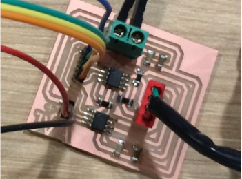 We use
a variation of Neil's hello.stepper.bipolar board
that control a step motor using Arduino. And was develop by our instructor Jorge Valerio
in Fab Academy 2016, and is still functioning. This board present the following
components:
We use
a variation of Neil's hello.stepper.bipolar board
that control a step motor using Arduino. And was develop by our instructor Jorge Valerio
in Fab Academy 2016, and is still functioning. This board present the following
components:
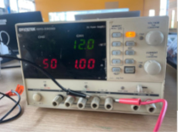 For the
test we have available a variable power supply from GwInstek - Model 3303D. The technical
manual provides
functioning information. It has three independent outputs: two with adjustable voltage level
and one with fixed level selectable from 2.5V, 3.3V and 5V. It consists of the following:
For the
test we have available a variable power supply from GwInstek - Model 3303D. The technical
manual provides
functioning information. It has three independent outputs: two with adjustable voltage level
and one with fixed level selectable from 2.5V, 3.3V and 5V. It consists of the following:
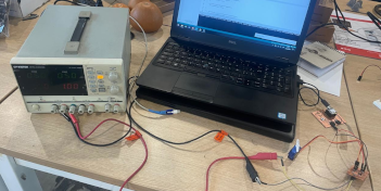
The following photo provides basic information regarding the power supply source, and also shows the
terminals where the wires need to be connected 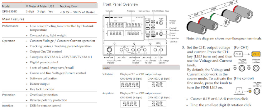
The test process consist on selecting a voltage and current and connect the board to the chanel terminal. For our testing we choose Chanel 1, because we tested a stepper motor we need to set the power supply with the following characteristics:
To make the test we made the following connections:
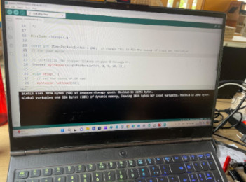 For functional
testing We write the following code in the Arduino IDE:
For functional
testing We write the following code in the Arduino IDE:
#include "Stepper.h".
const int stepsPerRevolution = 200;change this to fit the number of steps per
revolution for your motor
Stepper myStepper(stepsPerRevolution, 8, 9, 10, 11); initialize the stepper library on
pins 8 through 11
int stepCount = 0; number of steps the motor has taken.
void setup() { initialize the serial port:
Serial.begin(9600);
};
void loop() { step one step.
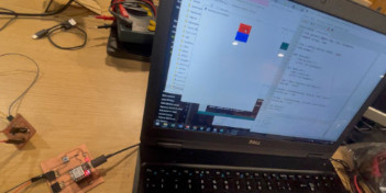
stepCount = Serial.read(); myStepper.step(stepCount); Serial.print("steps:"); Serial.println(stepCount); delay(500); }; The following photo provides show all system connection to test. The Nema Motor have 4 pins and requieres
12V 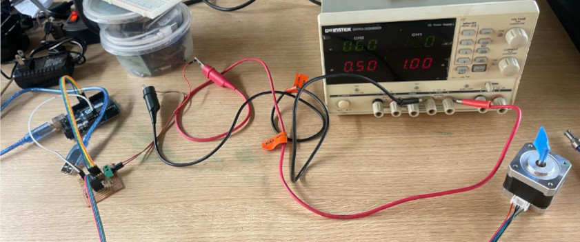
The following video show the testing process. We set 1A as imput current and the consumption was 0.99A and 10V. Thus, we get 9.9W
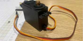
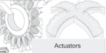
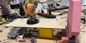
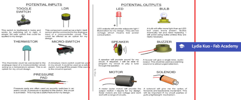
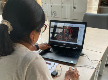
With my instructor support, we review the components that I'm gonna need for my final project in
order to decide which output could be the starting point. So I decide to start with a Servo motor
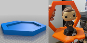
that I'll probably use to open the hidden shelve. The following picture show the potential devices
that I would use for my final project. I would use 2 Servo Motors, so the option could be to
fabricate one or two boards. I decide to fabricate one. 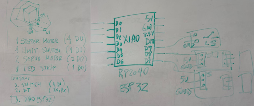
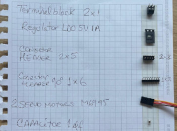 By
acknowledging that servo motors function with 5V and common power supply sources provide 12V, we
select the following components for this main board. It consists of the following:
By
acknowledging that servo motors function with 5V and common power supply sources provide 12V, we
select the following components for this main board. It consists of the following:
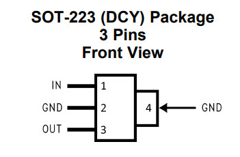 Regarding
the Low Dropout Regulator, we review technical information here
, and in summary its key technical characteristics are the following:
Regarding
the Low Dropout Regulator, we review technical information here
, and in summary its key technical characteristics are the following:
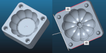
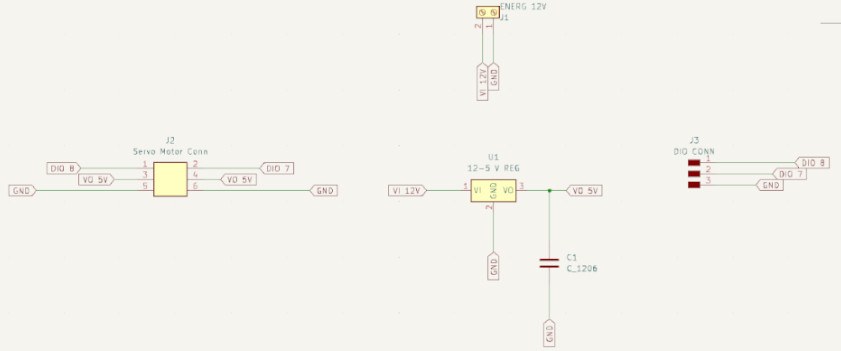
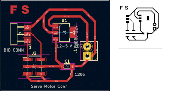
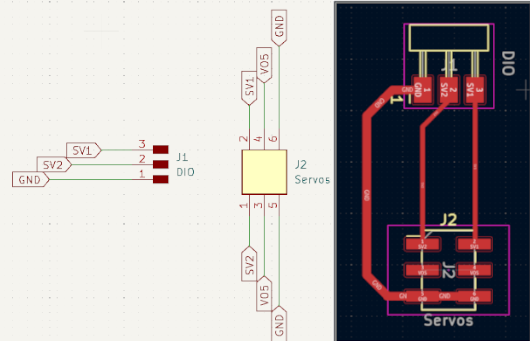
We select KiCad to design our board, taking into account that when working on schematics, we need to be careful with labeling each component in/out or GND adequately. Further we need to phycally recognise each component, because we made a mistake on regulator pins order, so when working on PCB editor traces were crossing, and took me sometime to understand the problem.
This is the schematic where you can see all the components. You can download Schematic design file
and the PNG file here.
 To obtain
PCB design and fabricate it, we need to take the following steps:
To obtain
PCB design and fabricate it, we need to take the following steps:
Select the PCB Editor File from the KiCad Principal Menu.
Update PCB from Schemnatic option located at Tools Menu on PCB Editor.
Set track sizes (width) and appereance (material) option located at Edit Board
SetUp Menu. Here we set 0.4 for traces width and 0.8 for ground and energy traces.
Setup constraints option located at Edit Board SetUp Menu. The most important
it is to setup cleareance at 0.4 to no exceed the end mill diameterStart drawing the traces selecting width and material correctlyThis is the pcb design where you can see all the components. You can download design file and
the SVG files here.
To fabricate PCB design we use SVG files applying following steps within FabModules Software:
Upload SVG Board file.
Convert SVG image inverted it using 1000dpi.
Set mill traces (material) using 1/64" end mill (select 2 as offsetting number).
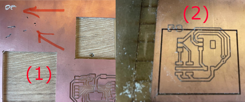
Calculated Mill raster 2D.Visualize the image selecting width and material correctlySend file as final stepApplied same steps for Cutting Edges but use 1/32" End MillThe machining was made with a Modela MDX-20. I have got the following problems while machining:
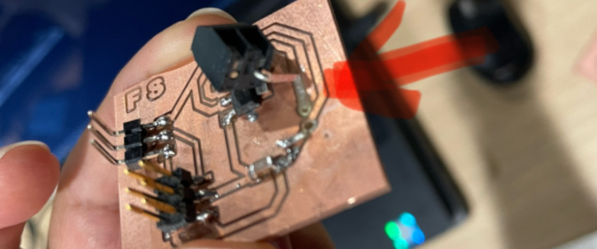
To proceed with soldering I fix the PCB with double contact tape. Thus, we can avoid any movement when tin soldering
I have a major problem with the terminal, because when selecting the componnets at the schematic, I didn't choose the correct model, and the distance between pins was shorter. Thus, after perforating the PCB the connector didn't fit. Thus I decided to fold the pins and tried to solder them. However the space between the capacitor and terminal's pins was short, and while soldering the cooper layer sliced. The following photo registered the problem. Thud, I have to machine another board and use new components
For functional
testing I used a modified coding provided by Adrian Torres
and follow this Arduino IDE coding:
Open Arduino IDE software.Connect the serial port to the board.Copy the original code provide by Adrian Torres.
#include <Servo.h>

Servo myservo;  // create servo object to control a servo
// twelve servo objects can be created on most boards


void setup() {
  myservo.attach(3);  // attaches the servo on pin to the servo object
}

void loop() {
  int pos;

  for (pos = 0; pos <= 180; pos += 1) { // goes from 0 degrees to 180 degrees
	// in steps of 1 degree
	myservo.write(pos);              // tell servo to go to position in variable 'pos'
	delay(15);                       // waits 15ms for the servo to reach the position
  }
  for (pos = 180; pos >= 0; pos -= 1) { // goes from 180 degrees to 0 degrees
	myservo.write(pos);              // tell servo to go to position in variable 'pos'
	delay(15);                       // waits 15ms for the servo to reach the position
  }
}
#include see Source file inclusion, in this case identifies Servo.h file from
Arduino IDE
library which need to be compiled and link with the code.void setup is a function that contains the initialization of the component that
I want to
control (output), or that will send me information (input)myservo.attach, attach the Servo variable to the pin 3 setting it as an outputvoid loop allows to repeat the code that follows over and over againint pos;, it is creating a variable called position, which limits will be set in
the following
code linesfor (pos = 0; pos <= 180; pos +=1), for statement is used to repeat a block of
output behave
enclosed between curly braces. In this case, we are establishing position variable to move from
0° to 180°myservo.write(pos); will call the variable set in the previous code line, in this
case to move in
relation to "for" statement from 0° to 180°delay (15) will set the time that will took the servo movement to go from 0° to
180°
for (pos = 180; pos >= 0; pos -= 1)In this case, we are establishing position
variable to return from 180° to 0°myservo.write(pos); will call the variable set in the previous code line, in this
case to move in relation to "for" statement from 180° to 0°delay (15) will set the time that will took the servo movement to go from 180° to
0°
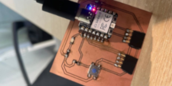
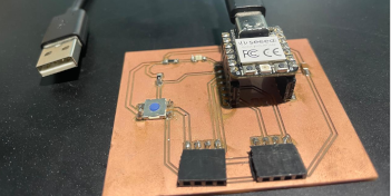
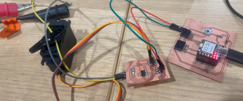
The following photo shows all system connection to test. I used XIAO RP2040 from Week 8 to test the board and the output device (Servomotor)
The final test was made runing the conding Arduino IDE and using a variable energy source, like shown in the following video
You can get access to the servo code here.
To complete the assignment with a code that I have to modified, I'm adding the information
regarding
the outputs that I added for my final project
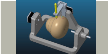
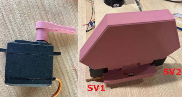
ServoMotors location
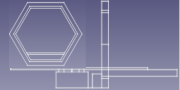
In this case, the servomortor(s) would be assigned to open and close my final project's
front top
My front top's mechanical design consider located them at right and left sides (like shown
in the
picture below).
 ServoMotors' PCB
The servomortor(s) open and close my fonal project's front top, and both need 5V to
function.
The difference regarding my 8th week assignment is that the energy source would come from a
power source that will convert 220V to 12v and then will go directly to a XL4015 5A voltage
and current regulator. This regulator will provide power to the main board (XiaoESP32-C3).
Thus, I consider better to connect directly to this convertor my servo motors. Hence I would
only need a PCB with pins for GND, energy and signals for both servos, with no need for any
other component, like shown in the figure below
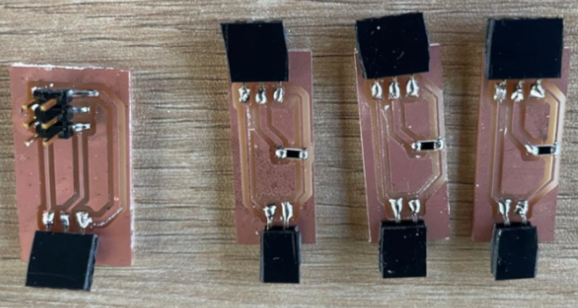
The following photo shows the 4 PCBs fabricated for the two servo motors (1st on the left) and 3 for the switches.
I made the program using Arduino IDE, which follow this schema integration, shown in the
following image.

This program was part of testing each of the components of my final project. This program is
only for the servo motors motion. I have to modifed modified the servo motor program to make
them move in different direction at the same time.
In this case, the open string to activate the system and open the door. At the
begining I included the Servo library needed that is included within ArduinoIde libraries
(like shown in the photo below). Then, I define the pins to declare the servo object.
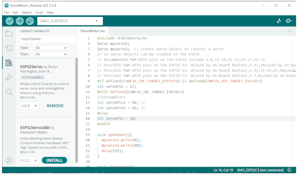
Then I declare using int the pins assigned to the servos. In this case D4 and
D5, considering that we are working with XiaoESP32-C3, following library indications (#elif
defined(CONFIG_IDF_TARGET_ESP32C3)).
The first void function includes the servo motors motion up to 90°. However,
because they start in different positions one is declare to move to 0° (D4) and the other
one needs to move to 90° (D5) to open the door simultaniously whit 25s delay.
The second void function includes the servo motors motion again up to 90°.
However, they took the new position, and the declare movement need to be make servo motor
move to the previous position. Thus, D4 is now declare to move to 90° and D5 declare to move
to 0° to close the door simultaniously whit 25s delay.
The library sets the standard to 50 hz for servos and define min/max motion force. Thus, afeter
testing, the min/max were set to 500us and 2500 us.
Finally the program sets to declare the begining positions of both servos thus D4 was set up to
90° (D4) and 0° (D5).
The code that I've used is the following one:
#include <ESP32Servo.h>
Servo myservo1;
Servo myservo2;  // create servo object to control a servo
// 16 servo objects can be created on the ESP32
// Recommended PWM GPIO pins on the ESP32 include 2,4,12-19,21-23,25-27,32-33
// Possible PWM GPIO pins on the ESP32-S2: 0(used by on-board button),
1-17,18(used by on-board LED),19-21,26,33-42
// Possible PWM GPIO pins on the ESP32-S3: 0(used by on-board button),
1-21,35-45,47,48(used by on-board LED)
// Possible PWM GPIO pins on the ESP32-C3: 0(used by on-board button),
1-7,8(used by on-board LED),9-10,18-21
#if defined(CONFIG_IDF_TARGET_ESP32S2) || defined(CONFIG_IDF_TARGET_ESP32S3)
int servoPin = 17;
#elif defined(CONFIG_IDF_TARGET_ESP32C3)
//Servomotors
int servoPin1 = D4; //
int servoPin2 = D5; //
#else
int servoPin = 18;
#endif

void openDoor(){
  myservo1.write(0);
  myservo2.write(90);
  delay(25);
}

void closeDoor(){
  myservo1.write(90);
  myservo2.write(0);
  delay(25);
}

void setup() {
	// Initialize Serial Monitor
	Serial.begin(115200);
	// Allow allocation of all timers
	ESP32PWM::allocateTimer(0);
	ESP32PWM::allocateTimer(1);
	ESP32PWM::allocateTimer(2);
	ESP32PWM::allocateTimer(3);
	myservo1.setPeriodHertz(50);    // standard 50 hz servo
	myservo2.setPeriodHertz(50);
	myservo1.attach(servoPin1, 500, 2500); // attaches the servo on pin 18 to the servo object
	myservo2.attach(servoPin2, 500, 2500);
	// using default min/max of 1000us and 2000us
	// different servos may require different min/max settings
	// for an accurate 0 to 180 sweep

	//Initial conditions
	myservo1.write(90);
	myservo2.write(0);
	delay(25);
	digitalWrite(enaPin, HIGH);
}
You can see in motion both servo motors in the following video
You can download the KidCad design files in the following links:
You can download the Arduino IDE file in the following links:

Wellcome to the process of trying to make almost something