12th week Assignment
Input Devices
Input Devices
First, it is neccesary to notice that exist different input devices. I found something very useful that help me understand at Lydia Kuo - Fab Academy 2023 Web Page. We decided to test a photoresistor module for the analog signal and flame detector (digital flame) as digital signal.
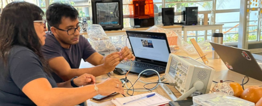
Please for group assignment details visit Anderson Zelarayan Web Page.
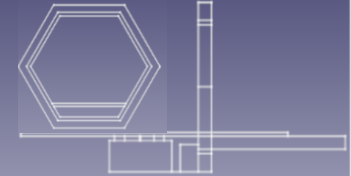
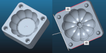
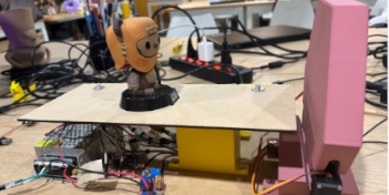
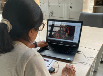
With my instructor support, we review the components that I'm gonna need for my final project in
order to select input device. The only input is a limit switch, that is going to activate all the
complete system to stop the stepper motor that will show the funko. The following picture show the
potential devices that I would use for my final project. 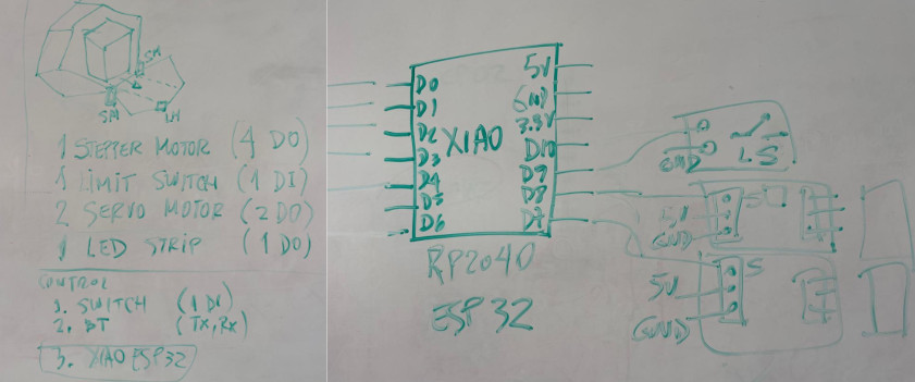
 By
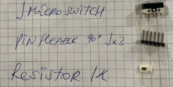
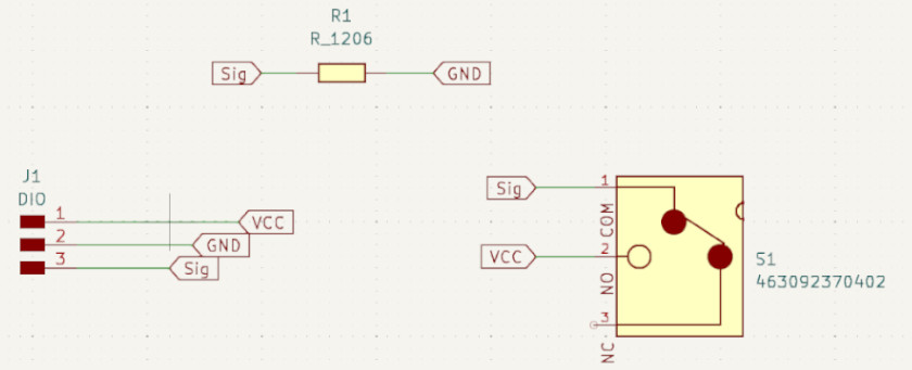
acknowledging that switch function we select the following components for this main board:
By
acknowledging that switch function we select the following components for this main board:
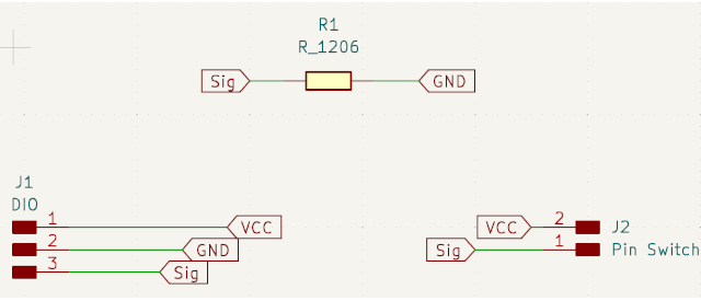
We need to include a pull-down resistor connected between the signal and GND, adding a 1kΩ resistor is often done to:
This 1kΩ resistor value is often chosen because it provides sufficient current limitation without significantly affecting the logic level voltages in typical digital circuits.
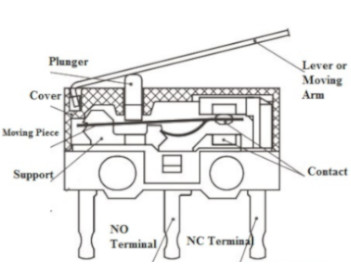 Switches are
basic
methods for opening and closing an electrical circuit. Microswitch, also called a
miniature snap-action switch, often used as safety devices because of their reliability
and sensitivity. The micro switch has three pins: Common (C), Normally Closing (NC), and
Normally
Opening (NO). Here, the Common pin is an input pin, the NC pin is Output 1, and the NO pin is
Output
2. The working principle of a micro switch is that when it touches an object, the contacts
change
position.
The normally closed pin of the circuit is opened and the normally open pin is closed when you
press
the lever of the switch. In the same way, when you open the lever of the switch, then the
normally
closed or NC pin of the circuit will carry the current, while the normally open or NO pin of the
circuit can isolate electrically. There are different types of microswitches, for more details
visit
Eleron Web Page.
Switches are
basic
methods for opening and closing an electrical circuit. Microswitch, also called a
miniature snap-action switch, often used as safety devices because of their reliability
and sensitivity. The micro switch has three pins: Common (C), Normally Closing (NC), and
Normally
Opening (NO). Here, the Common pin is an input pin, the NC pin is Output 1, and the NO pin is
Output
2. The working principle of a micro switch is that when it touches an object, the contacts
change
position.
The normally closed pin of the circuit is opened and the normally open pin is closed when you
press
the lever of the switch. In the same way, when you open the lever of the switch, then the
normally
closed or NC pin of the circuit will carry the current, while the normally open or NO pin of the
circuit can isolate electrically. There are different types of microswitches, for more details
visit
Eleron Web Page.
 Regarding
switches types, the circuits vary from simple make/break circuits to multi-makes and multi-break
circuits. We will use a SPDT microswitch (Single Pole, Double Throw). Simply stated, there is
one
common terminal on the switch where the voltage and current is applied and that voltage and
current
can be either directed to the normally open or normally closed terminal. The direction of the
current flow is typically directed by a mechanical roller lever that actuates the switch. For
more
details visit this web page .In summary its key technical characteristics are the
following:
Regarding
switches types, the circuits vary from simple make/break circuits to multi-makes and multi-break
circuits. We will use a SPDT microswitch (Single Pole, Double Throw). Simply stated, there is
one
common terminal on the switch where the voltage and current is applied and that voltage and
current
can be either directed to the normally open or normally closed terminal. The direction of the
current flow is typically directed by a mechanical roller lever that actuates the switch. For
more
details visit this web page .In summary its key technical characteristics are the
following:
We select KiCad to design our board, taking into account that we will need to upload a library for the microswitch. I search for platforms and forums, and localize this this web page . That suggest me to downloaded a library from snapEDA . You can download the KiDCad library here.The folder containts a how to import instructions for more details When working on schematics, we need to be careful with labeling each component in/out or GND adequately having on mind its possible PCB paths. Further, we need to phycally recognise each component, because the microswitch will need to made perforations, and the library could present some diferences.
This is the schematic where you can see all the components.
 To
obtain
PCB design and fabricate it, we need to take the following steps:
To
obtain
PCB design and fabricate it, we need to take the following steps:
Select the PCB Editor File from the KiCad Principal Menu.
Update PCB from Schemnatic option located at Tools Menu on PCB Editor.
Set track sizes (width) and appereance (material) option located at Edit Board
SetUp Menu. Here we set 0.4 for traces width and 0.8 for ground and energy traces.
Setup constraints option located at Edit Board SetUp Menu. The most important
it is to setup cleareance at 0.4 to no exceed the end mill diameterStart drawing the traces selecting width and material correctlyThis is the pcb design where you can see all the components.

To fabricate PCB design we use SVG files applying following steps within FabModules Software:
Upload SVG Board file.
Convert SVG image inverted it using 1000dpi.
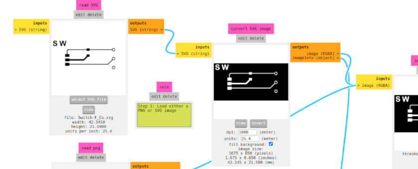
Set mill traces (material) using 1/64" end mill (select 2 as offsetting
number).
Calculated Mill raster 2D.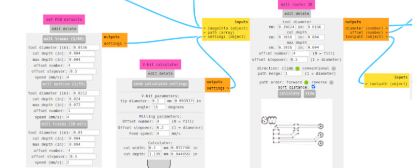
Visualize the image selecting width and material correctly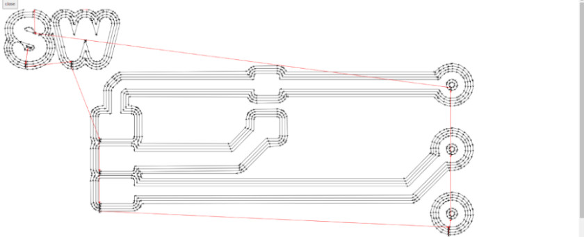
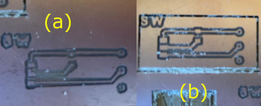
Send file as final stepApplied same steps for Cutting Edges but use 1/32" End MillThe machining was made with a Modela MDX-20. I have got the following problems while machining:
The PCBs images:
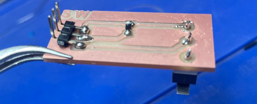
To proceed with soldering I fixed the PCB with double contact tape. Thus, we can avoid any movement when tin soldering
The final PCB image is shown below
 For
functional
testing I used two Arduino IDE libraries (button and bouncing).
The first code for button is:
For
functional
testing I used two Arduino IDE libraries (button and bouncing).
The first code for button is:
const int buttonPin = 2; the number of the pushbutton pin.
const int ledPin = 13;the number of the LED pin.
int buttonState = 0;variable for reading the pushbutton status
void setup() { initialize the LED pin as an output:
pinMode(ledPin, OUTPUT); initialize the pushbutton pin as an input:
pinMode(buttonPin, INPUT);initialize the pushbutton pin as an input:
}
void loop() { buttonState = digitalRead(buttonPin);read the state of the pushbutton value:
if (buttonState == HIGH) {check if the pushbutton is pressed. If it is, the
buttonState is HIGH: digitalWrite(ledPin, HIGH);turn LED on:} else { digitalWrite(ledPin, LOW);turn LED off:}}const int buttonPin = 2; the number of the pushbutton pin.
const int ledPin = 13;the number of the LED pin.
int ledState = HIGH;the current state of the output pin
int buttonState; the current reading from the input pin
int lastButtonState = LOW; the previous reading from the input pin
unsigned long lastDebounceTime = 0;the last time the output pin was toggled
unsigned long debounceDelay = 50;the debounce time; increase if the output
flickers
void setup() { pinMode(buttonPin, INPUT);pinMode(ledPin, OUTPUT);digitalWrite(ledPin, ledState);set initial LED state} void loop() {int reading = digitalRead(buttonPin);read the state of the switch into a local
variableif (reading != lastButtonState) {If the switch changed, due to noise or
pressing
lastDebounceTime = millis();reset the debouncing timer} if ((millis() - lastDebounceTime) > debounceDelay) {whatever the reading is
at,
it's been there for longer than the debounce delay, so take it as the actual current state
if (reading != buttonState) {if the button state has changedbuttonState = reading; if (buttonState == HIGH) {only toggle the LED if the new button state is HIGH
ledState = !ledState; } } } digitalWrite(ledPin, ledState);set the LEDlastButtonState = reading;save the reading. Next time through the loop, it'll
be
the lastButtonState } I have a major problem with the testing, because the resistor was the right one(it seems that instead of provide me one of 1K, in the fab lab I got one of 10K), and was causing short circuit. Thus I have to change the resistor
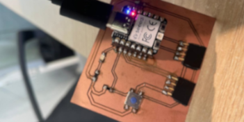
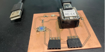
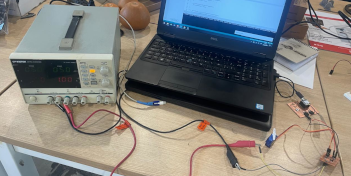
The following photo shows all system connection to test. I used XIAO RP2040 from Week 8 to test
the
board and the output device (Servomotor) 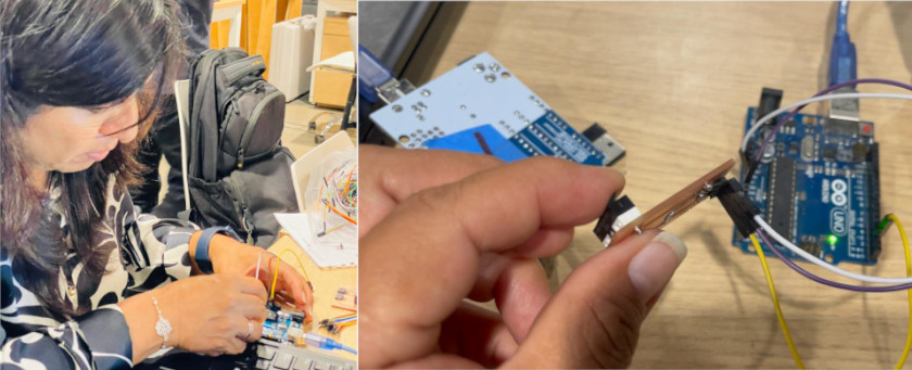
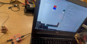
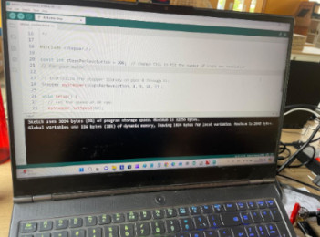
The first test was made runing the coding Arduino IDE for buttom, like shown in the following video
The final test was made runing the coding Arduino IDE for bouncing, like shown in the following video
You can download the SVG files here.
To complete the assignment with a board that I develop, I'm adding the information regarding
the immputs that I added for my final project
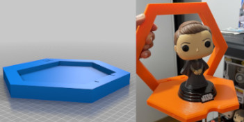
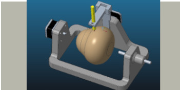
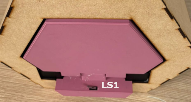
Limit Switches
I have 3 micro limit switches. One located at the base of the front top that will be clicked
when the shelf is open and the signal will activate the motion platform. (See following photo)
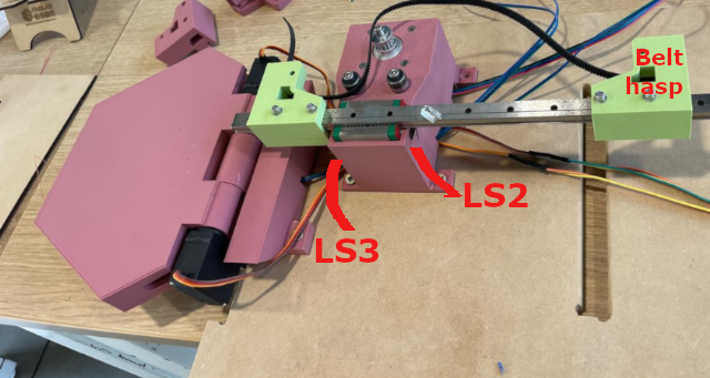
The others two are located within the stepper motor case, just behind the linear rail in both
sides. Thus when the motion platform activates, the belt hasp will reach one limit swith and
send the message to stop stepper motor motion.
Then when the signal to close the shelf top activate the stepper motor motion again in reverse,
the other belt hasp reach the other limit swith to again stop the motor motion and send the
signal to close the shelf's top (see the picture below)
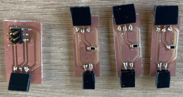
Limit switches' PCBs
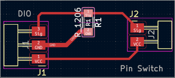
For my final project I desinged 3 PCBs for micro limit switches. In this case, because
each limit switch is place in different locations, their PBCs only include
pins GND, Signal and energy that comes from the XiaoESP32-C3 and a 1k resistor. I machined 3
PCBs, each of them have the following design
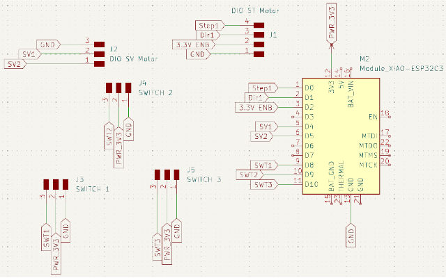
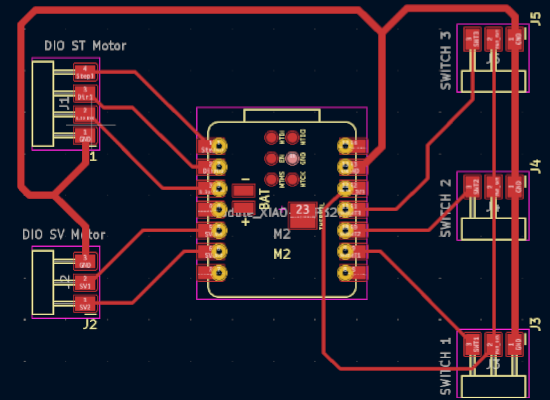
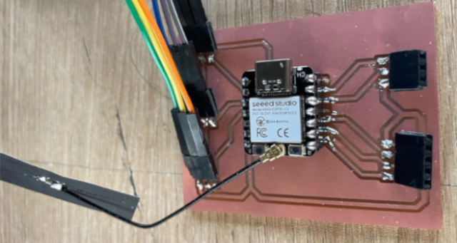
Main Board: XiaoESP32-C3 PCB
I used XiaoESP32-C3 with 16 pins, and I placed 3 groups of 3 pin headers for the 3 micro
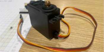
limit switches (Signal, GND and 3V energy). The rest I used for the Stepper Motor (4 pins)
And for the servo motors (3 pins - 2 for each servo motor signals and 1 that provides GND
for both). You can see its schematic and PBC desing in the photos below, and in the last
on, at left side you can observe the 3 group of pines for the switches.
The following photo shows the 4 PCBs fabricated for the two servo motors (1st on the left) and 3 for the switches.
Finally the photo below shows the Main PCBs fabricated for XiaoESP32-C3.
I made the program using Arduino IDE, which follow this schema integration, shown in the following
image.

Because the motion will be activated by bluethooth LightBlue App to send open and close action by
string. I'm not a complete exprt in programing, but the good thing is that I used the programs of in
my previous assigments, and to integrate them my instructors provide me a lot of support. First to
modified the servo motor program to make the movement in different direction at the same time. And
then to integrate the delays between the signals that provide the micro limit switches that allows
to activate and stop the stepper motor motion.
In this case, the open string to activate the system and open the door. Then the motor
gets in forward motion until reaching a limit switch that will stop the motor movement. The
close string will activate stepper motor backward motion until reach the next switch.
Finally, the order will be to acticate the servo motors backward motion to close the shelf.
At the begining I included the libraries needed (include bluethoot conexion and servos controller).
Then, I define the pins for steppers motors and switches, to declare the servo object.
The first and second void function includes the servo motor motion up to 90° to open
and close whit 25s delay. The following two void function is to activate the stepper
motor motion forwards and backwards
After I include the information about the connection to bluethooht (adding the information that suggest Xiao). And then defining that the commnad that will received will be a string. The declaring what will happen with "open" string (open the door) and then declaring the movement with "close" string, each of then with 1000ms delay.
Then comes the part of the code that bring details about the servo motion with 50 hz and their connection with the stepper motor motion (where says "set pins"). Considering that the servos motion in different directions, this part of the coding declare the initial position of both. As you can see on start on 0° and the other one at 90°. At the end the network name connection is declare as "FabLab"
the code that I've used is the following one:
#include <BLEDevice.h>
#include <BLEUtils.h>
#include <BLEServer.h>
#include <ESP32Servo.h>
//StepperMotor
#define stepPin D0
#define dirPin D3
#define enaPin D2
#define stepsPerRevolution 200
//Switches
#define swIn D8
#define swOut D7
#define swOpen D9

Servo myservo1;
Servo myservo2;  // create servo object to control a servo
// 16 servo objects can be created on the ESP32
// Recommended PWM GPIO pins on the ESP32 include 2,4,12-19,21-23,25-27,32-33
// Possible PWM GPIO pins on the ESP32-S2: 0(used by on-board button),1-17,18(used by on-board LED),19-21,26,33-42
// Possible PWM GPIO pins on the ESP32-S3: 0(used by on-board button),1-21,35-45,47,48(used by on-board LED)
// Possible PWM GPIO pins on the ESP32-C3: 0(used by on-board button),1-7,8(used by on-board LED),9-10,18-21
#if defined(CONFIG_IDF_TARGET_ESP32S2) || defined(CONFIG_IDF_TARGET_ESP32S3)
int servoPin = 17;
#elif defined(CONFIG_IDF_TARGET_ESP32C3)
//Servomotors
int servoPin1 = D4; //
int servoPin2 = D5; //
#else
int servoPin = 18;
#endif

int statIn = 0;
int statOut = 0;
int statOpen = 0;

void openDoor(){
  myservo1.write(0);
  myservo2.write(90);
  delay(25);
}

void closeDoor(){
  myservo1.write(90);
  myservo2.write(0);
  delay(25);
}

void moveForward(){
  digitalWrite(stepPin, HIGH);
  delayMicroseconds(2000);
  digitalWrite(stepPin, LOW);
  delayMicroseconds(2000);
}

void moveBackward(){
  digitalWrite(stepPin, LOW);
  delayMicroseconds(2000);
  digitalWrite(stepPin, HIGH);
  delayMicroseconds(2000);
}

// Define the UUIDs for the BLE service and characteristics
#define SERVICE_UUID        "6698670f-5b28-4069-bcb1-9276ed443012"
#define CHARACTERISTIC_UUID "56caf526-b906-46b1-a4c9-9eef3ac8cbeb"

// BLE Server Callbacks
class MyCallbacks : public BLECharacteristicCallbacks {
	void onWrite(BLECharacteristic *pCharacteristic) {
		String value = pCharacteristic->getValue();

		if (value.length() > 0) {
			Serial.print("Received Value: ");
			for (int i = 0; i < value.length(); i++)
				Serial.print(value[i]);

			Serial.println();
			statIn = digitalRead(swIn);
			statOut = digitalRead(swOut);

			// Check for 'open' or 'close' commands
			if (value == "open") {
				openDoor();  // Open the door
				delay(1000);
				digitalWrite(dirPin, HIGH);
				do{
				  moveForward();
				  statIn = digitalRead(swIn);
				  Serial.println(statIn);
				}while(statIn != 1);
				Serial.println("Door Opened");
			} else if (value == "close") {
				digitalWrite(dirPin, LOW);
				do{
				  moveForward();
				  statOut = digitalRead(swOut);
				  Serial.println(statOut);
				}while(statOut != 1);
				delay(1000);
				closeDoor(); // Close the door
				Serial.println("Door Closed");
			}
		}
	}
};

void setup() {
	// Initialize Serial Monitor
	Serial.begin(115200);
	// Allow allocation of all timers
	ESP32PWM::allocateTimer(0);
	ESP32PWM::allocateTimer(1);
	ESP32PWM::allocateTimer(2);
	ESP32PWM::allocateTimer(3);
	myservo1.setPeriodHertz(50);    // standard 50 hz servo
	myservo2.setPeriodHertz(50);
	myservo1.attach(servoPin1, 500, 2500); // attaches the servo on pin 18 to the servo object
	myservo2.attach(servoPin2, 500, 2500);
	// using default min/max of 1000us and 2000us
	// different servos may require different min/max settings
	// for an accurate 0 to 180 sweep

	// Set pins
	pinMode(stepPin, OUTPUT);
	pinMode(dirPin, OUTPUT);
	pinMode(enaPin, OUTPUT);
	pinMode(swIn, INPUT);
	pinMode(swOut, INPUT);
	pinMode(swOpen, INPUT);

	//Initial conditions
	myservo1.write(90);
	myservo2.write(0);
	delay(25);
	digitalWrite(enaPin, HIGH);

	// Initialize BLE
	BLEDevice::init("FabLab");
	BLEServer *pServer = BLEDevice::createServer();
	BLEService *pService = pServer->createService(SERVICE_UUID);

	// Create a BLE characteristic
	BLECharacteristic *pCharacteristic = pService->createCharacteristic(
										 CHARACTERISTIC_UUID,
										 BLECharacteristic::PROPERTY_READ |
										 BLECharacteristic::PROPERTY_WRITE
									   );

	// Set the callback for receiving data
	pCharacteristic->setCallbacks(new MyCallbacks());
	pCharacteristic->setValue("Waiting for commands...");

	// Start the service
	pService->start();

	// Start advertising
	pServer->getAdvertising()->start();
	Serial.println("Waiting for a client to connect...");
}

void loop() {
	// Nothing to do here, waiting for BLE commands
}
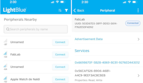
In this case, I established a Cellphone connectivity with the microcontroller using the
LightBlue App, that you can dowload from AppStore (iPhone), which recognise first the
"FabLab" network that the XiaoESP32-C3 send. The App provides at the begining a list
of all available networks, we need select it and click on Connect
Once connected we see the network data.
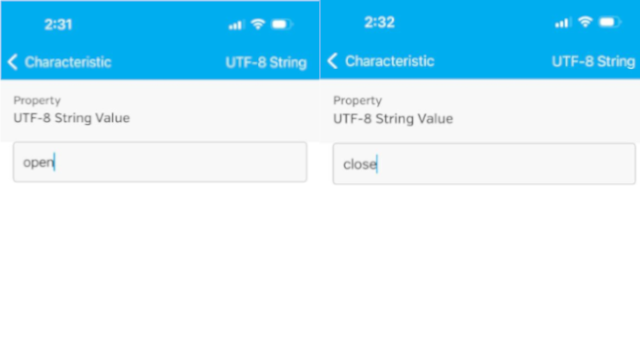
The following screen swill show two options write new value and
Read. We choose write new value and the app ask to select the
type of value. Here we need to choose UTF-8 String
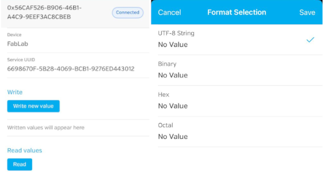
To activate the shelf motion we need to write open and to close it to write
close. You will notice that the time difference between open and close order
is one minute
YOu can see in motion The Motorized Hidden Pop Up Shelf that I develop
You can download the KidCad design files in the following links:
You can download the Arduino IDE file in the following links:

Wellcome to the process of trying to make almost something