WEEK 12
Input devices
Group Assignment:
- Probe an input device's analog levels and digital signals
Individual Assignment:
- Measure something: Add a sensor to a microcontroller board that you have designed and read it
This week, we tested some sensors we have in the lab. We also remenber how to use the oscilloscope and milled a pcb for the sensor, and we used the microcontroller borad we made in the Electronic production week.
Group Assignment
For the group part, we tested two sensors: a photoresistor and a flame sensor. We used an Arduino Uno to display the variation in the value read at the input pin on the Arduino's serial monitor.

KY-18
The KY-18 is an analog sensor with a photoresistor, its resistance value changes depending on the light that falls on it. To test it, we wrote a small program and connected it to an analog input on the Arduino. The program can send the input value via serial, but we also connected the oscilloscope's probe to this input to observe the voltage variation.
int sensorPin = A2;
int sensorValue = 0;

void setup() {
  Serial.begin(9600);
  pinMode(13,OUTPUT);
}
void loop() {
  sensorValue = analogRead(sensorPin);
  sensorValue = map(sensorValue,0, 1023, 0, 255);
  Serial.println(sensorValue);
  analogWrite(13,sensorValue);
  delay(300);
}
We set the oscilloscope to each vertical division equals 2V and each horizontal division equals 25ms. We observed how the voltage value changes when we shine light on and cover the photoresistor.
KY-26
The KY-26 is a flame sensor with both an analog and a digital output, the sensitivity of which can be adjusted by rotating the potentiometer that includes. To test it, we used the following program, which we uploaded to the Arduino.
int led = 13;
int digitalPin = 12;
int analogPin = A0;
int digitalVal;
int analogVal;

void setup(){
	pinMode(led, OUTPUT);
	pinMode(digitalPin, INPUT);
	pinMode(analogPin, INPUT);
	Serial.begin(9600);
}
void loop(){
	digitalVal = digitalRead(digitalPin);
	if(digitalVal == HIGH) {
		digitalWrite(led, HIGH);
	}else{
		digitalWrite(led, LOW);
}
analogVal = analogRead(analogPin);
Serial.println(analogVal);
delay(100);
}
To test the analog part, we connected the oscilloscope's probe to the sensor's analog output. In the presence of a flame, the voltage value changes, drawing a curve from 5V to 0V. This variation is also observed when the flame moves away. The sensor also has its own LED that lights up in the presence of a flame.
In the digital part, we moved the oscilloscope's probe to the digital output. We observed that the behavior is more like a switch; in the presence of a flame, the voltage value changes from 5V to 0V instantaneously, drawing steps instead of curves.
Individual Assignment
A1325
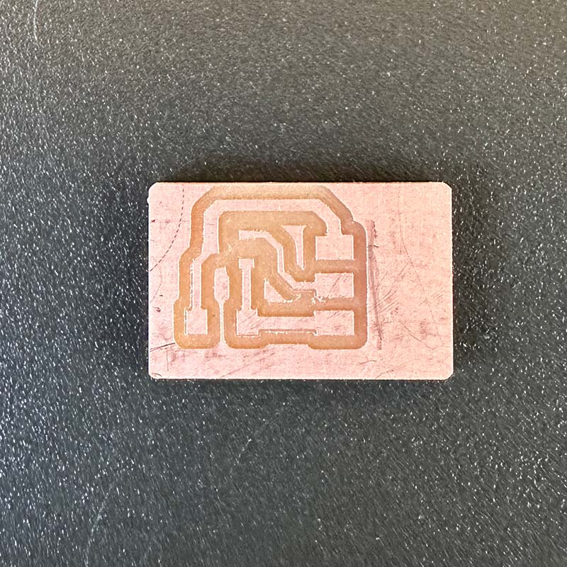
For the individual assignment, I designed a small board for the A1325, which is a Hall effect sensor. I used the typical circuit shown in the datasheet.
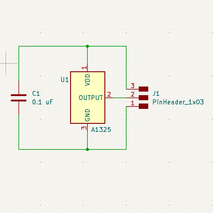
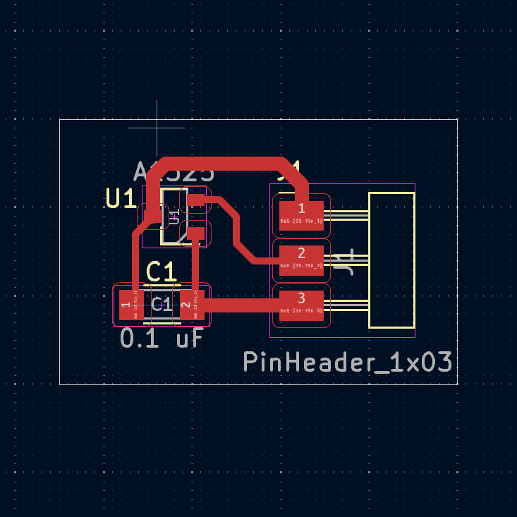
The circuit is quite simple and only includes a capacitor. The following images show the circuit with the components soldered on.
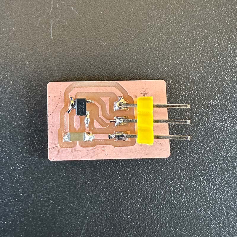
To test it, I used the board I made during the electronic production week which uses a Xiao RP2040, It was connected to a small SSD1306 display that uses the I2C protocol to communicate with the microcontroller.
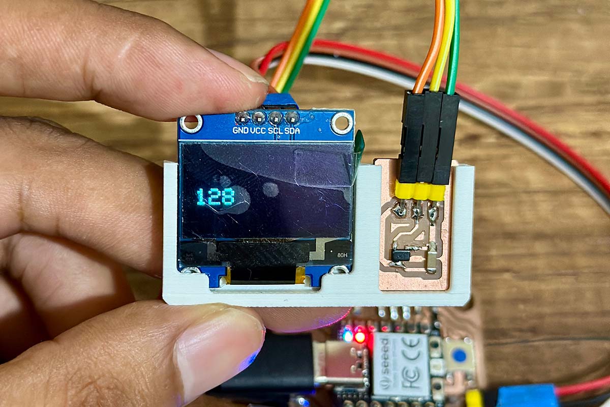
To test it, I used the following program that reads the value from the sensor's analog output. It also sends this value by serial and displays it on the screen.
#include <Wire.h>
#include <Adafruit_GFX.h>
#include <Adafruit_SSD1306.h>

#define SCREEN_WIDTH 128 // OLED display width, in pixels
#define SCREEN_HEIGHT 64 // OLED display height, in pixels
#define OLED_RESET -1 // Reset pin # (or -1 if sharing Arduino reset pin)

Adafruit_SSD1306 display(SCREEN_WIDTH, SCREEN_HEIGHT, &Wire, OLED_RESET);

int sensorPin = 27;    // analog input pin RP2040 pin 27
int sensorValue = 0;  // variable to store the value coming from the sensor

void setup() {

	display.begin(SSD1306_SWITCHCAPVCC, 0x3C);
	delay(2000);
	display.clearDisplay();
	display.setTextColor(WHITE);
	Serial.begin(9600); // initialize serial communications
	pinMode(28,OUTPUT);
}

void loop() {

	display.clearDisplay();
	sensorValue = analogRead(sensorPin); // read the value from the sensor
	sensorValue = map(sensorValue,0, 1023, 0, 255);
	Serial.println(sensorValue); // print value to Serial Monitor
	analogWrite(28,sensorValue);

	display.setTextSize(2);
	display.setCursor(0, 28);
	display.print(sensorValue);

	display.display();
	delay(300);
}
As shown in the video, the value displayed is 128 when there is no magnetic field present. When a magnet is brought close, this value decreases, and it increases when the magnet is reversed.
Download:
Here you can download de printable parts of the mechanical structure: