Final Project
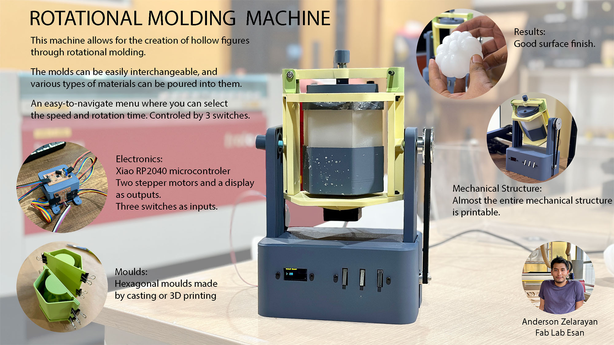
Rotational moulding machine
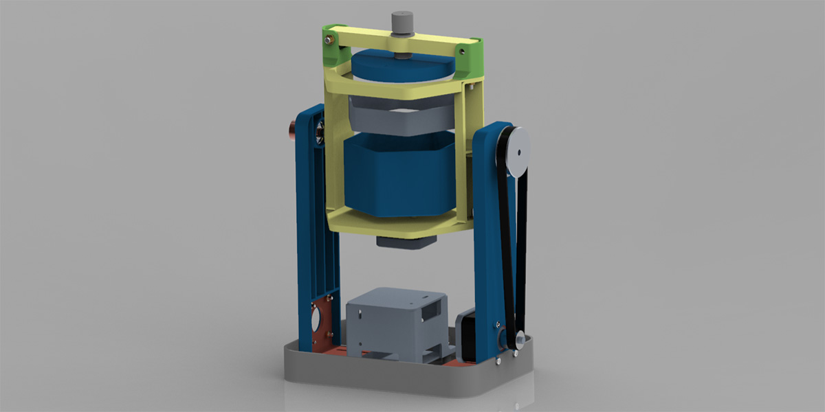
Final Result
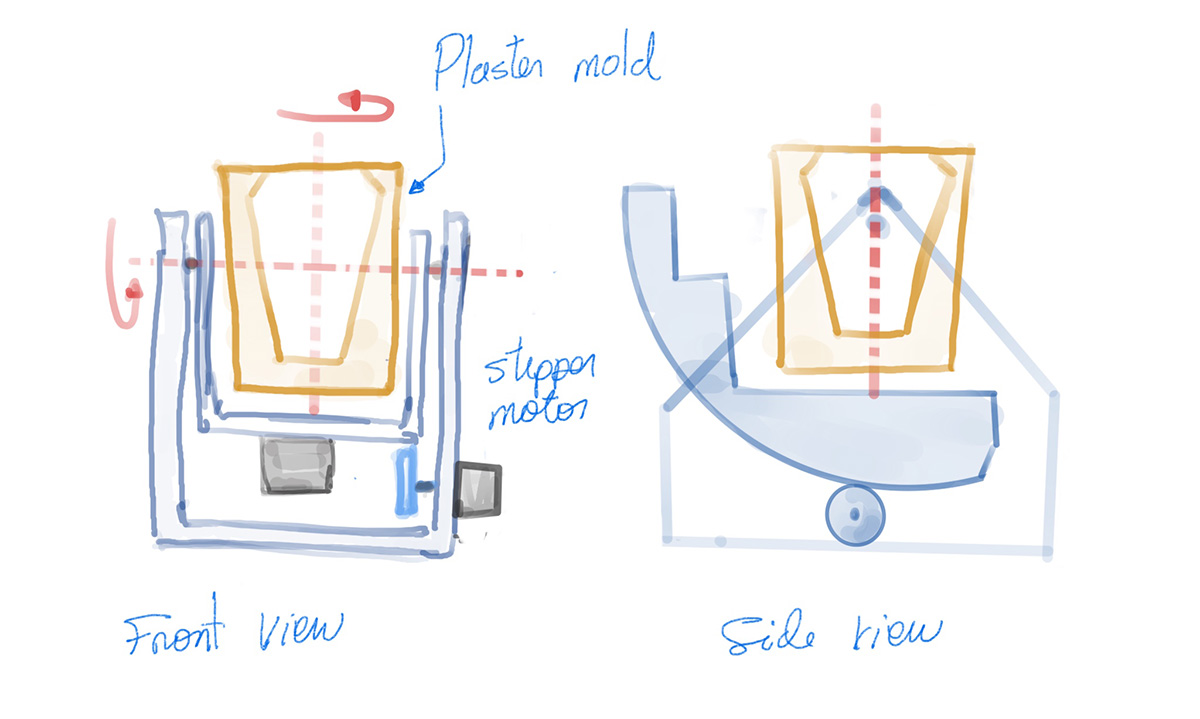
Sketching
The project I propose is a rotational molding machine. The idea is to pour a liquid material into a mold. The mold will rotate on two main axes. The goal is that the material adhere to the mold walls as it solidifies, thus creating hollow objects. At the beginning, I had many ideas about which material to use. I was considering ceramics, wax, epoxy, cement, or even chocolate. The material for the mold could also vary: PLA, silicone, plaster, etc. Finally, I decided to use silicone molds, and the material to test would be wax. The following image shows a sketch of the machine.
Mechanical Desing
I faced several challenges when designing the mechanical system of the machine. The requirements I had in mind were as follows:
- The machine must be compact.
- The machine must allow rotational movement on two axes.
- It should allow easy loading and unloading of the mold.
- It should facilitate easy pouring of the material.
- The structure should be mostly 3D printed.
- The structural parts should be printed without using supports.
- The structural parts should not take too much time to print.
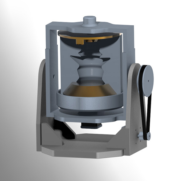
This is the evolution of the mechanical design. The first version had larger parts. The issue with this was the printing time. I realized that if any part needed a change, it would have to be reprinted, taking much longer in the design process. That's why, in the second design, there are smaller parts that will be joined with screws.
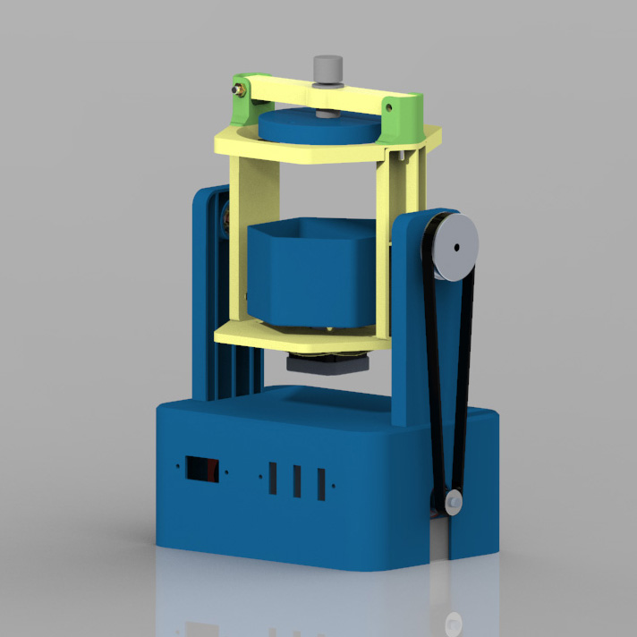
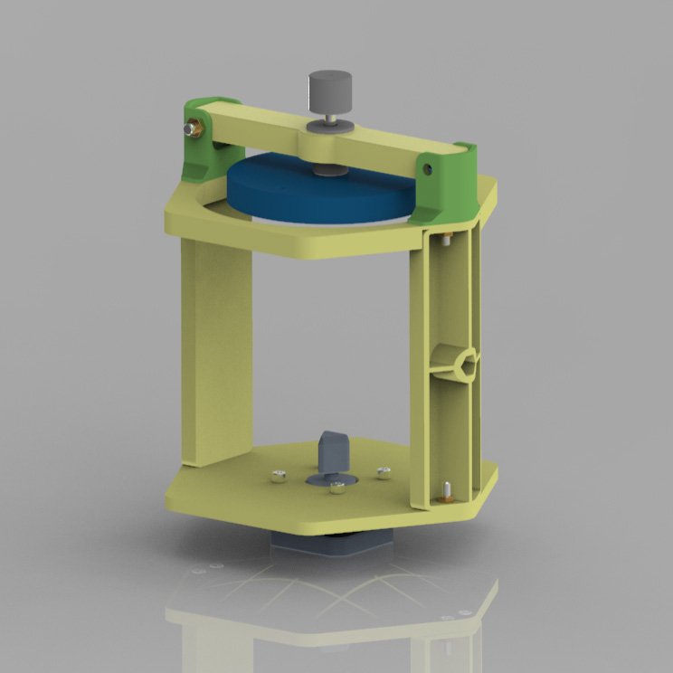
This is how the final assembly looks after removing the casing. It consists mainly of a base, two side panels, and the secondary block, which will hold the mold and rotate.
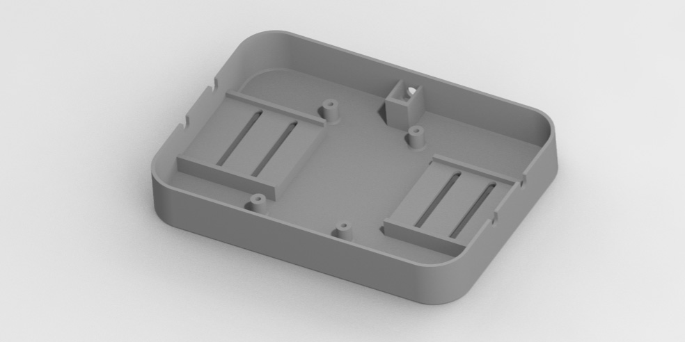
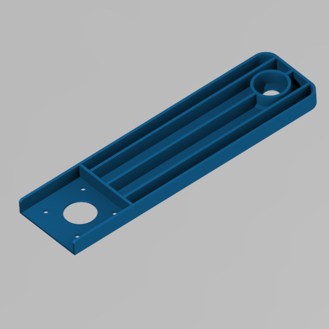
As with all the parts that will be printed, the base was designed with thin 2mm walls. It also has slots to fit the 90-degree brackets, holes to mount the electronic components, and a slot to place the power jack socket.
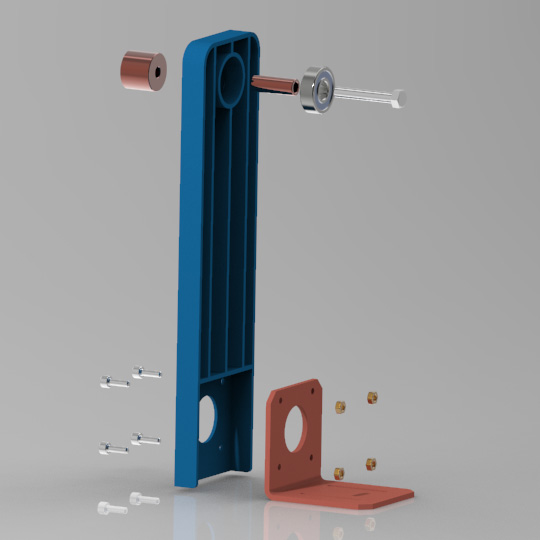
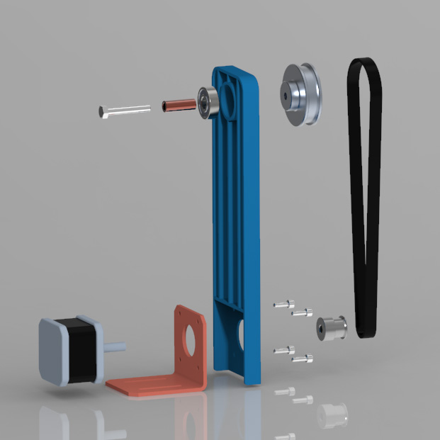
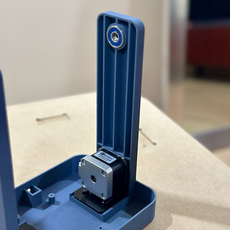
The side panels will support the rotation axis of the secondary block. To transmit power, I used a 400 mm belt. The side panels are designed so that this size of belt is properly tensioned. I used 608 bearings on the axes to ensure a smoother movement.
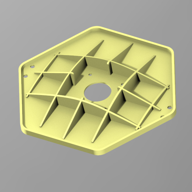
This is the secondary block that will hold the mold and also will rotate. It has a structure where the mold lid is fixed, which facilitates the pouring process. It also has a bearing in the rotating part.
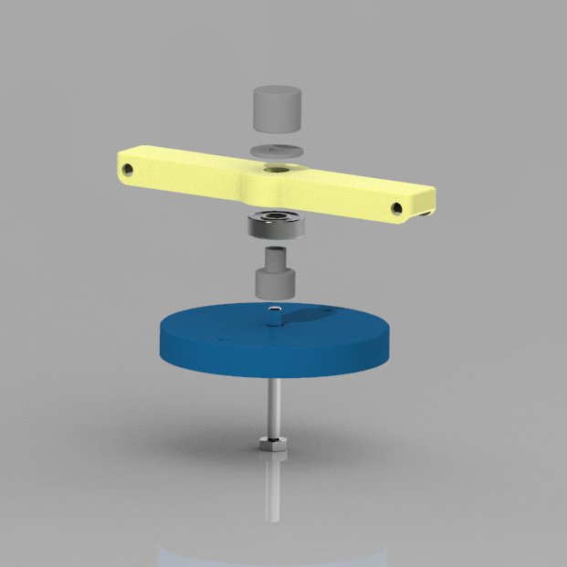
In this case, the power will be transmitted through a small triangular block. The main mold holder also has a slot of the same shape and it was designed with a clearance. This way, when mounting the mold in the machine, it will be easily aligned.
For this prototype, I have designed shell structures to improve printing time and enhance the design process.
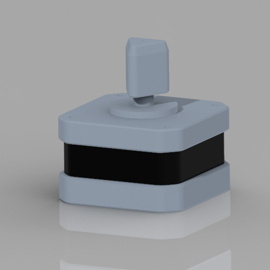
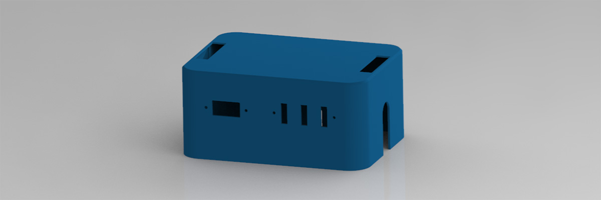
This is the case, which will cover the internal components and also hold the switches and the LED display.
Mold Desing
The mold design was also a challenge. It had to meet the following considerations:
- It must facilitate the pouring of the material.
- It should not allow the material to escape through the parting lines.
- It must be easy to align.
- Its manufacturing process should be quick.
With these considerations in mind, I decided to design a three-part mold. One of these parts would serve as a lid and have a conical shape that would act as a funnel, facilitating the pouring of the material.
For the tests, I used a pumpkin-shaped figure with two small legs. To align the mold, I designed a continuous U-shaped groove, and the male side of the mold has a tongue with the same shape. This feature will serve as extra protection to prevent the liquid material from leaking out of the mold.
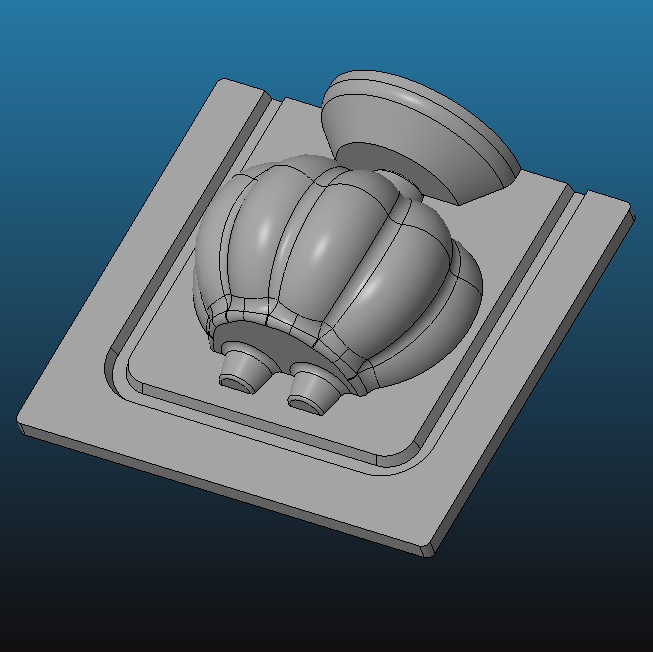
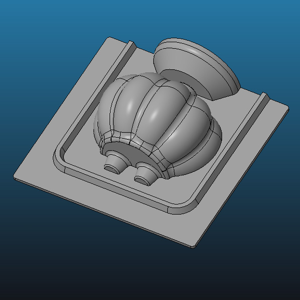
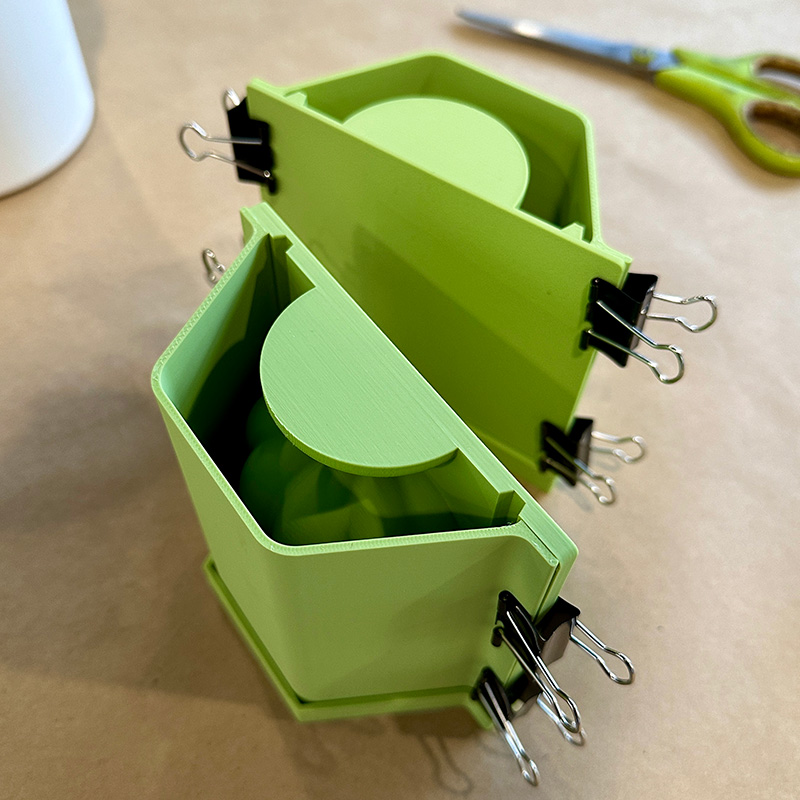
These are the assemblies of the negatives for pouring the silicone into the molds.
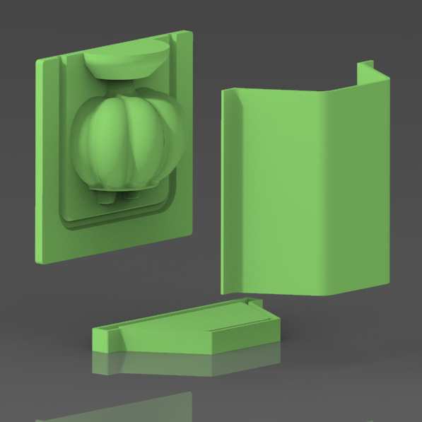
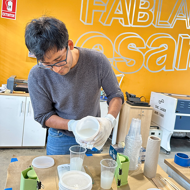
I decided to make the molds with food-grade silicone because I would like to try making chocolate figures at some point. I bought the silicone from a local supplier, and it needed to be mixed in a 50/50 ratio. I used approximately 200 grams of the mixture for each half of the mold and around 50 grams for the lid. I also used some hooks to help close the negatives.
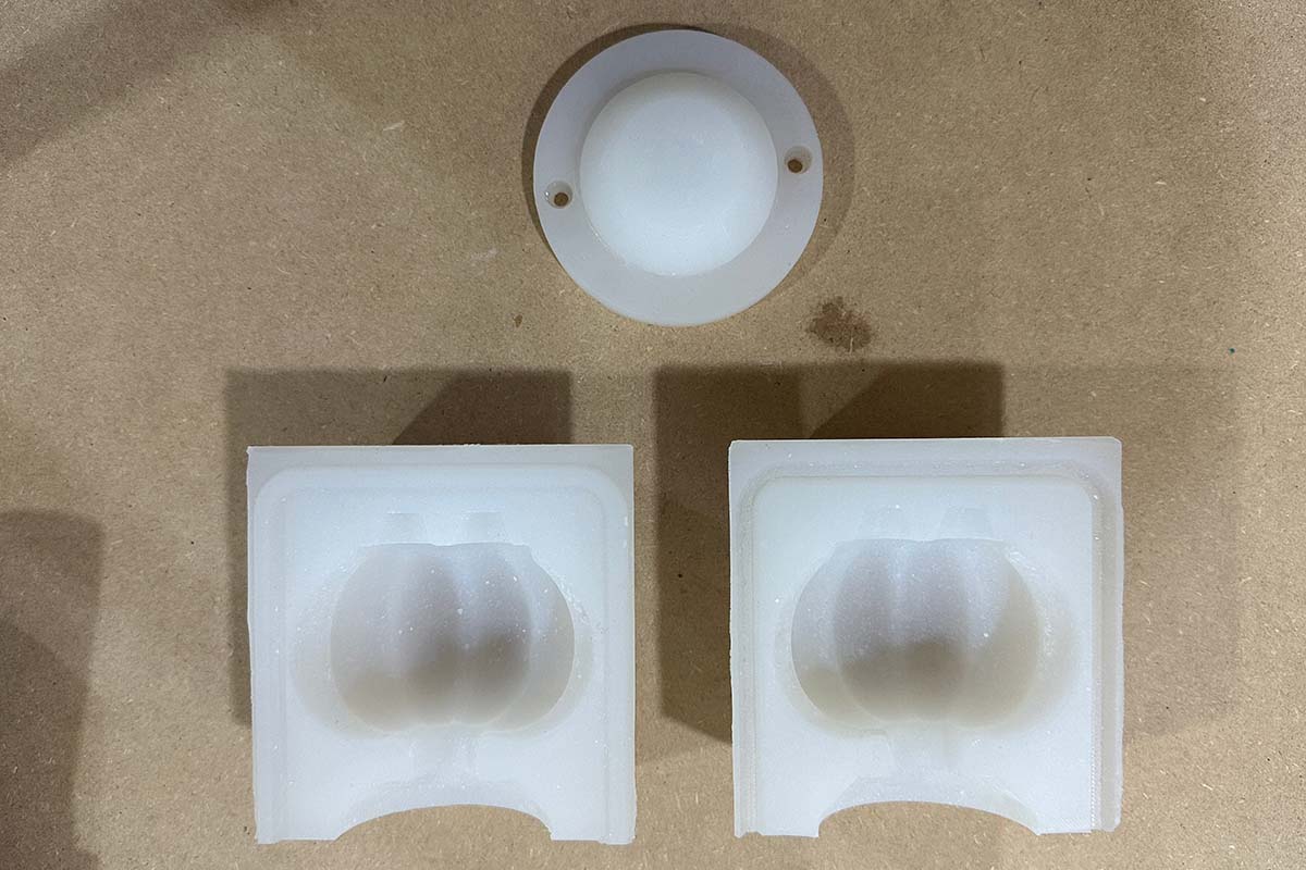
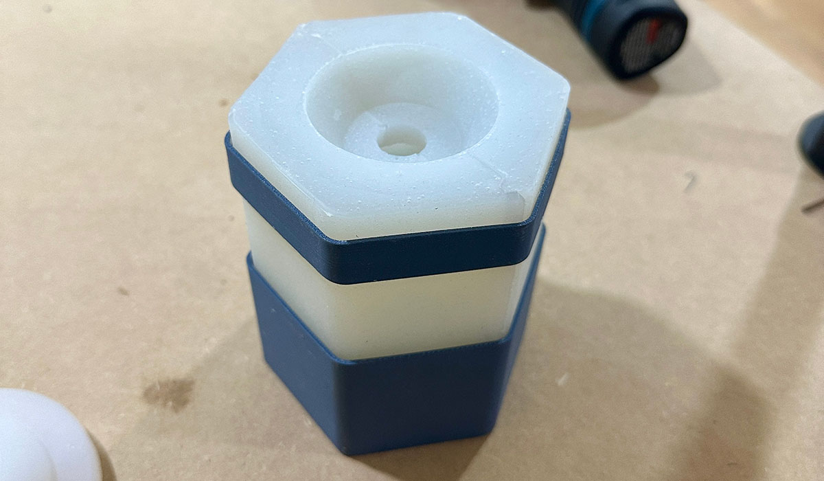
This is the result. They look very well, although you can see some lines from the print layers left by the negatives (these were printed with a layer height of 0.08 mm).
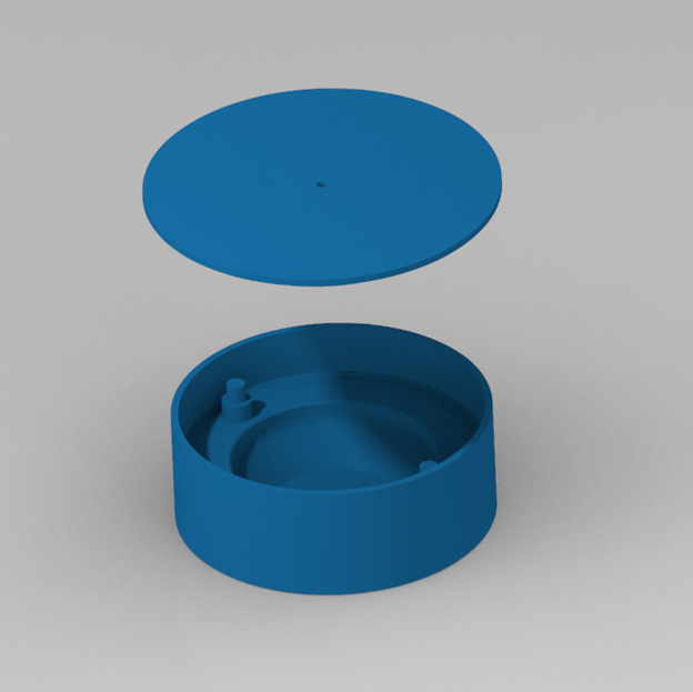
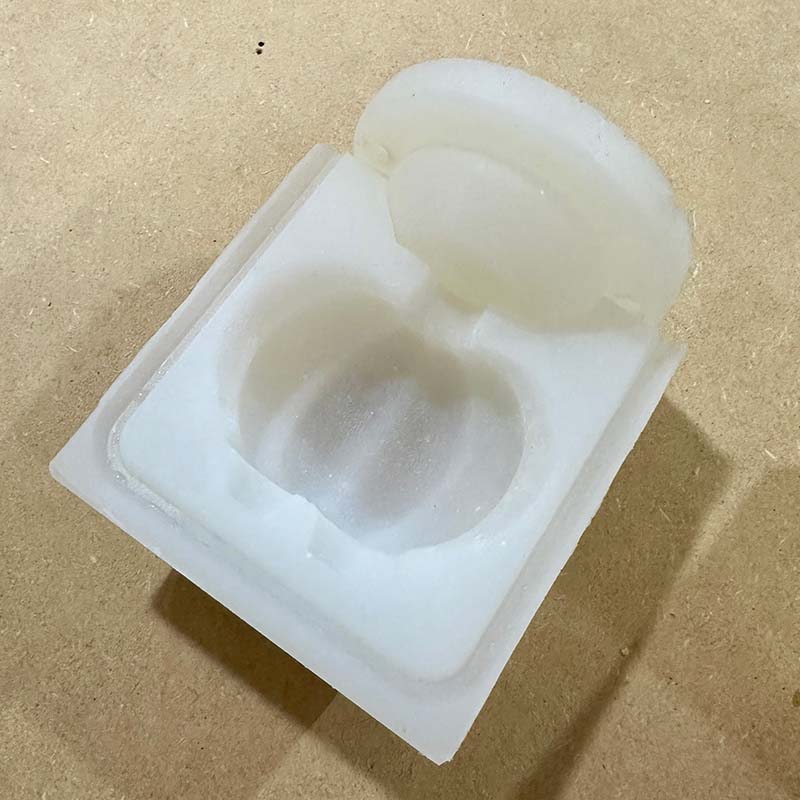
In the following images, you can see that the molds close well with both halves and the lid. Note that there is a small clearance in the heights of the groove and the tongue of the mold halves, which helps the mold close better.
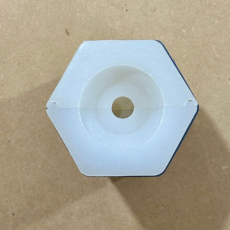
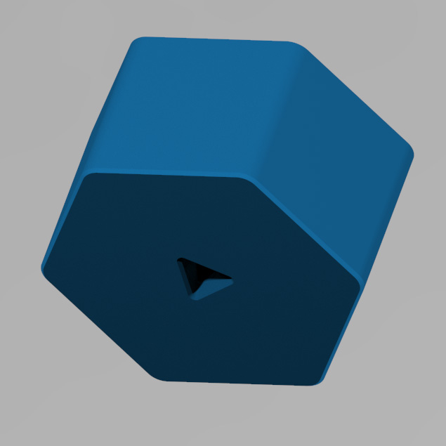
Finally, this is the mold closed and placed inside the main holder and the secondary holder, which has a hexagonal ring shape that matches the mold. This design helps keep the mold in place despite the rotational movement. This component can be detached from the machine for demolding.
Electronic Design
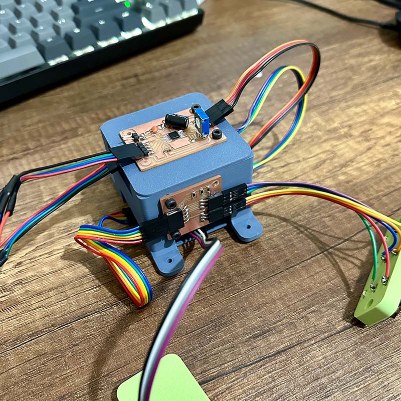
For this project, I have designed three electronic boards: the main one, which will mount the XIAO-RP2040; the stepper motor controller, based on a DRV8428; and one to connect the switches that will control the machine.
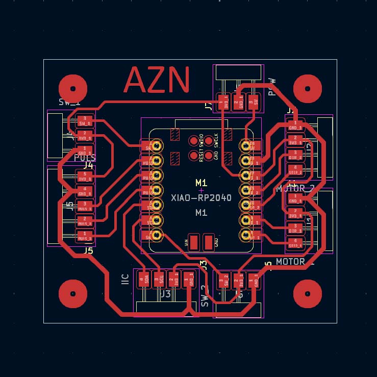
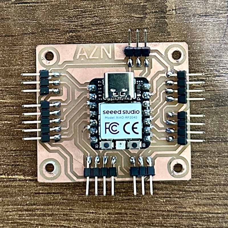
Main board: The main board basically has connections for the different modules: motor 1, motor 2, switches, and display. I also left some connections that could be used to connect additional sensors.
| Item | Components | Amount | Price per Unit ($) |
|---|---|---|---|
| 1 | SEEED STUDIO XIAO RP2040 | 1 | 6.0 |
| 2 | MALE BERG STRIP | 1 | 0.5 |
| 3 | FEMALE BERG STRIP | 1 | 0.5 |
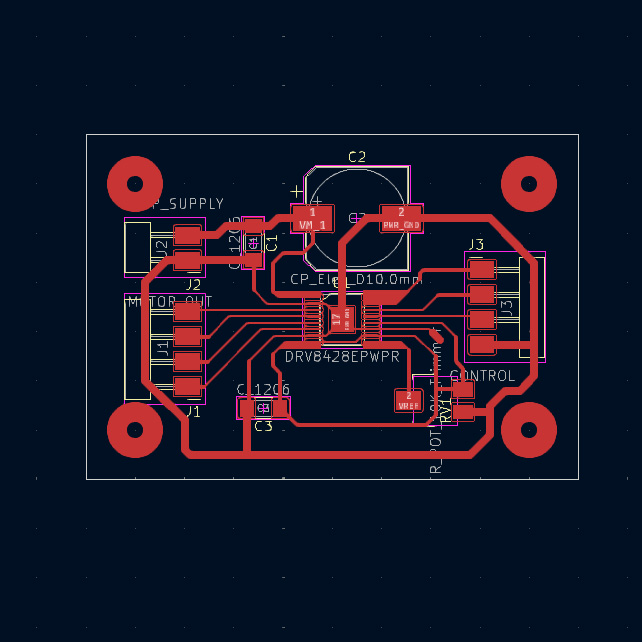
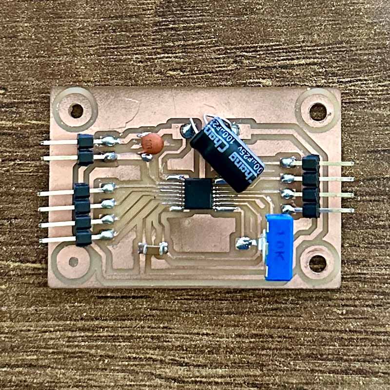
Stepper motor driver board: The motor controller follows the typical circuit recommended by the manufacturer of the DRV8428. Also, it has connections to the motor, the main board, and the 12V power supply.
| Item | Components | Amount | Price per Unit ($) |
|---|---|---|---|
| 1 | DRV8428 | 1 | 8.0 |
| 2 | ELECTROLYTIC CAPACITOR 100 uF | 1 | 1.0 |
| 3 | CAPACITOR 0.01 uF | 1 | 0.5 |
| 4 | CAPACITOR 1 uF SMD | 1 | 0.5 |
| 5 | TRIMMER 10k | 1 | 1.0 |
| 6 | MALE BERG STRIP | 1 | 0.5 |
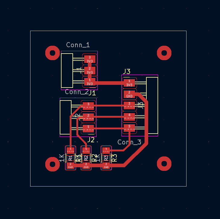
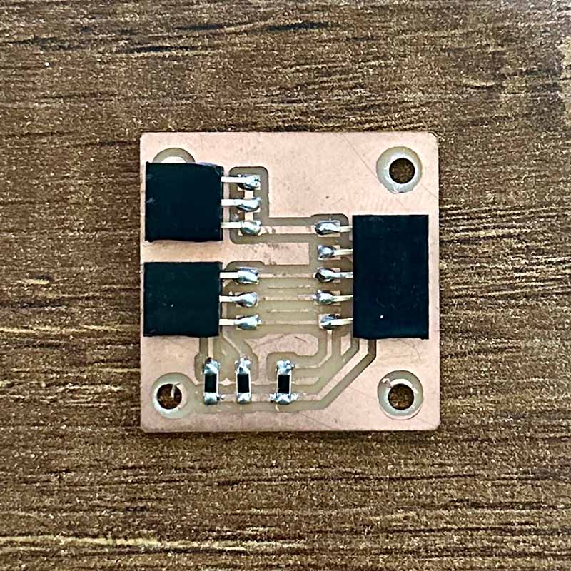
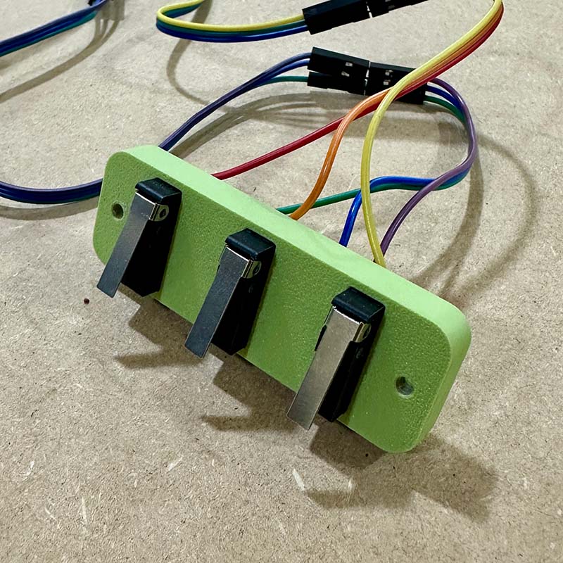
Swithc board: The board is quite simple; it only has the pull-down resistors for the switches.
| Item | Components | Amount | Price per Unit ($) |
|---|---|---|---|
| 1 | RESISTOR 1K SMD | 3 | 0.1 |
| 2 | FEMALE BERG STRIP | 1 | 0.5 |
Software
In summary, the program aims to control two motors with a speed and rotation time chosen by the user. This will allow to use materials that require different solidification times.
To achieve this goal, I set predetermined speeds and rotation times.
Speeds: 20%, 40%, 60%, 80%, and 100%
Rotation times: 1 min, 2 min, 3 min, 4 min, and 5 min
With these predefined speeds and times, it's easy to navigate and select using only three switches:
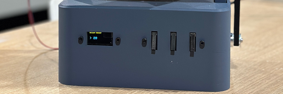
- First switch: Back
- Second switch: Forward
- Third switch: Select
System Integration
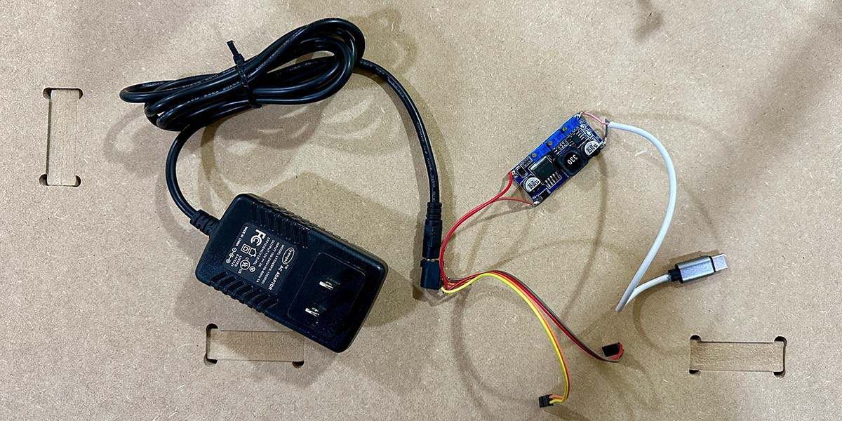
One of the goals for this project was to make the system compact and self-contained. For this reason, I decided to use a 12V, 3A power supply as shown in the image. This is connected to a power jack socket, which provides 12V power for each stepper motor and is also connected to a voltage regulator configured to output 3.3V. This 3.3V output is used to power the Xiao through a USB-C cable.
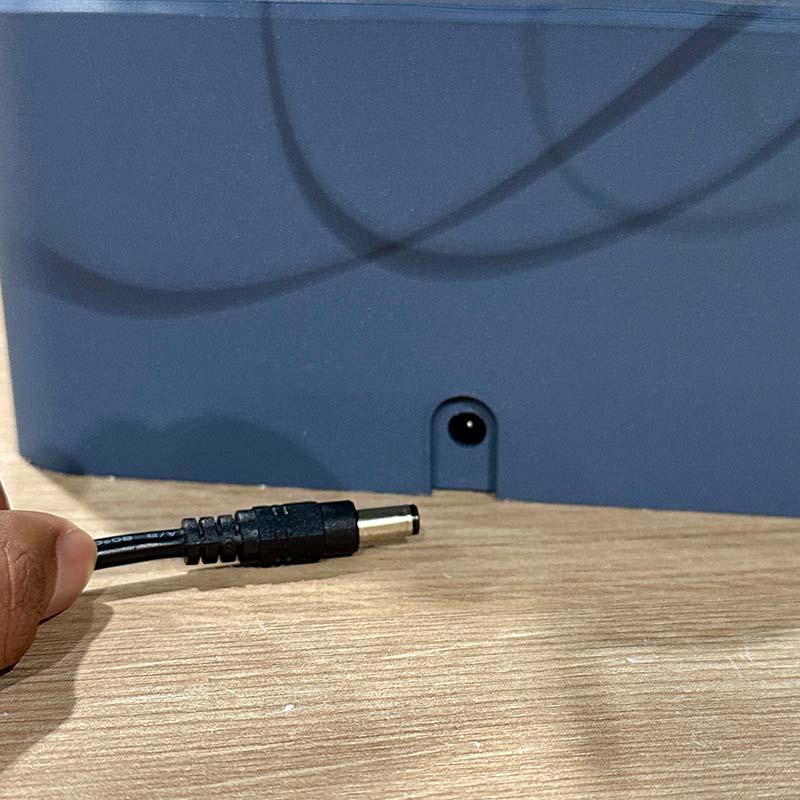
The main base has a slot for the power jack socket, and the power supply connector is attached from the back.
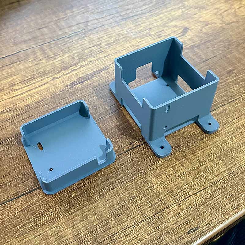
I also designed a box to hold all the electronic components. It has a cover where the motor controllers are mounted, allowing access to the interior where the main controller is located. It attaches to the main base with M3 screws.
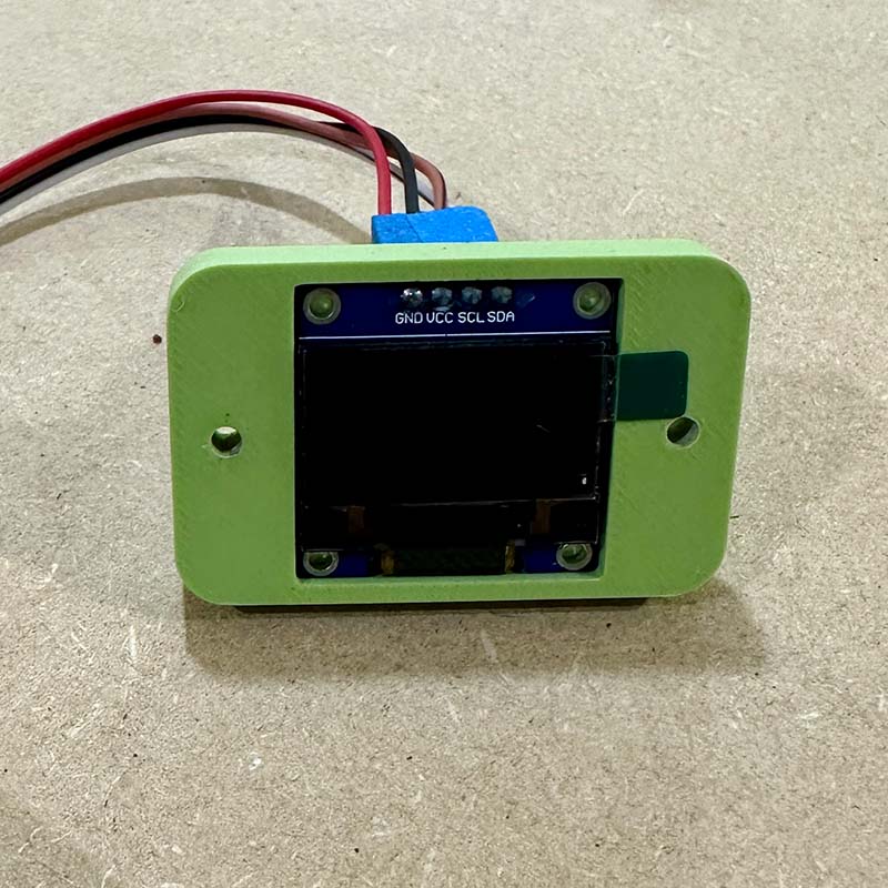
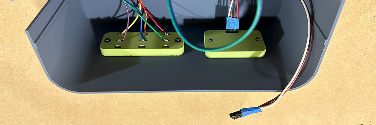
I also designed small supports where the three switches and the SSD1306 screen will be mounted. These supports are attached to the case of the machine with M3 screws.
This is how both supports look when attached to the case.
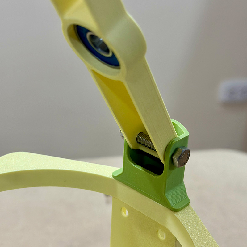
Most of the printed parts are connected using screws and their respective nuts. In the main axes, is used steel screws, providing rigidity to the structure. Where rotation is involved, there is a bearing to allow for smoother rotation.
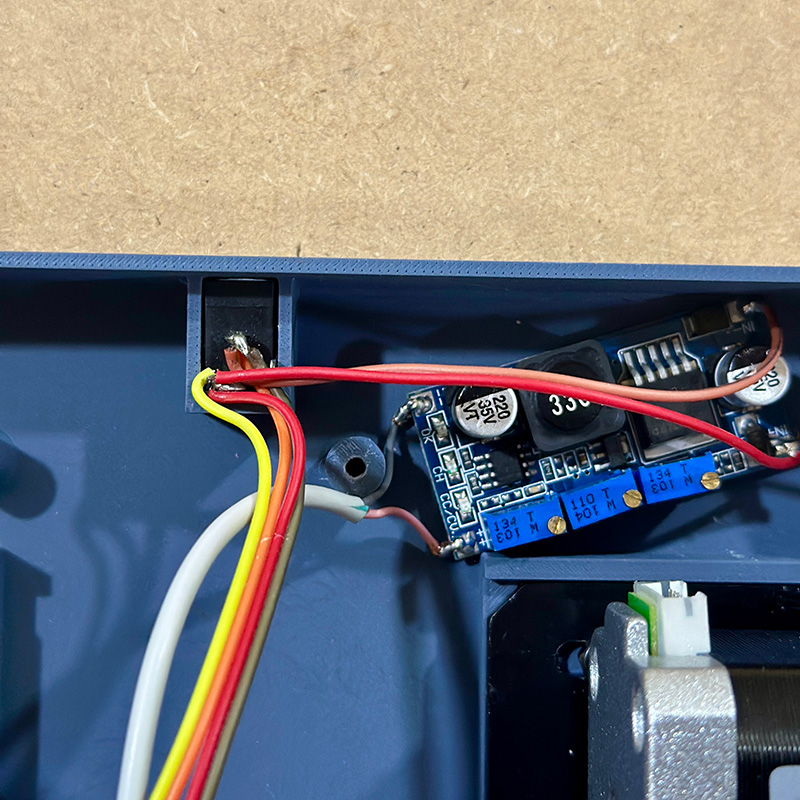
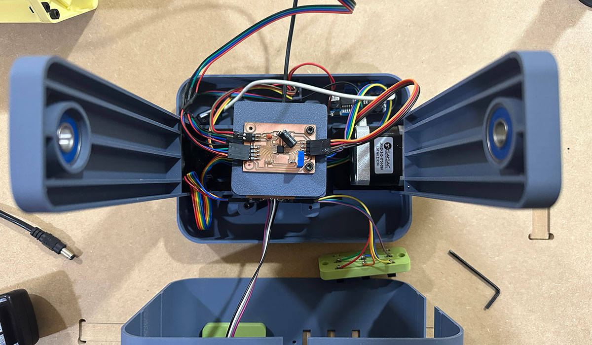
These are all the components on the main base. It looks very well, although reducing the length of the cables could improve it.
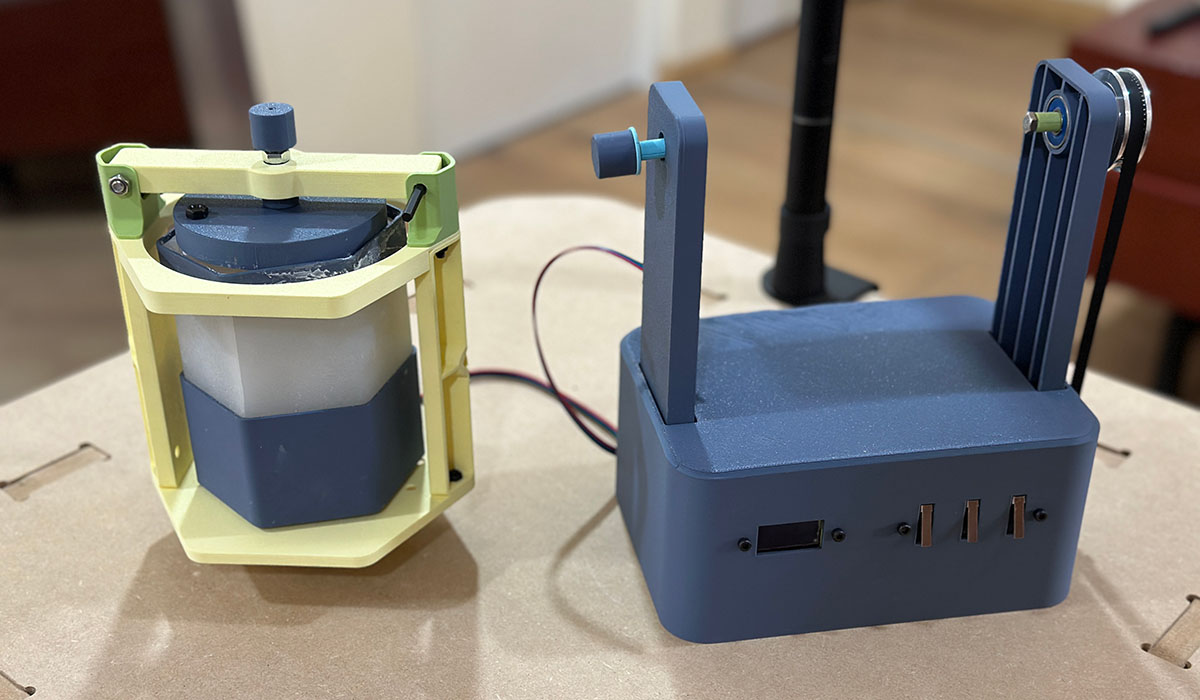
Finally, these are the two main parts of the machine. They are connected by the control cable of the stepper motor of the secondary block. The secondary block will never make a full rotation, so we won't have any problems with the cable obstructing the movement.
Other additional componets I used for assembly the machine were the following:
| Item | Components | Amount | Price per Unit ($) |
|---|---|---|---|
| 1 | NEMA 17 STEPPER MOTOR | 1 | 12.0 |
| 2 | NEMA 17 STEPPER MOTOR LOW PROFILE | 1 | 12.0 |
| 3 | NEMA 17 STEPPER MOTOR 90° BRACKET | 2 | 3.0 |
| 4 | 2GT16-5MM PULLEY | 1 | 1.0 |
| 5 | 2GT60-5MM PULLEY | 1 | 2.5 |
| 6 | 2GT-400MM BELT | 1 | 3.0 |
| 7 | 608 BEARING | 3 | 1.0 |
| 8 | LM2596S VOLTAGE REGULATOR | 1 | 2.0 |
| 9 | POWER JACK SOCKET | 1 | 0.5 |
| 10 | POWER SUPPLY 12V 3A | 1 | 3.0 |
| 11 | SSD1306 DISPLAY | 1 | 5.0 |
| 12 | LIMIT SWITCH | 3 | 1.0 |
| 13 | M5x30 SCREW | 3 | 1.0 |
| 14 | M5 HEX NUT | 1 | 0.5 |
| 15 | 1/4"x2" SCREW | 1 | 1.0 |
| 16 | 1/4" HEX NUT | 1 | 0.5 |
| 17 | M3x8 SOCKET HEAD SCREW | 20 | 0.1 |
| 18 | M3 HEX NUT | 5 | 0.1 |
| 19 | M4x12 SOCKET HEAD SCREW | 16 | 0.1 |
| 20 | M4 HEX NUT | 16 | 0.1 |
| 21 | USB C CABLE | 1 | 5.0 |
Testing
The following is the test for navigating the menu and starting the machine's movement.
The following video shows a test of demolding and rotation times for the wax. It's important to ensure the wax is at the right point of solidification before demolding to avoid this kind of issues. Since we don't exactly control the temperature of the wax when it enters to the mold, the solidification time can vary significantly. A useful reference I found for knowing when to demold, is the wax left in the container, once it is almost solidified, the mold can be safely demolded.
Here is a successful demolding. As you can see in the video, The figure is easily removed from one side, but it was necessary to be careful with the other side.
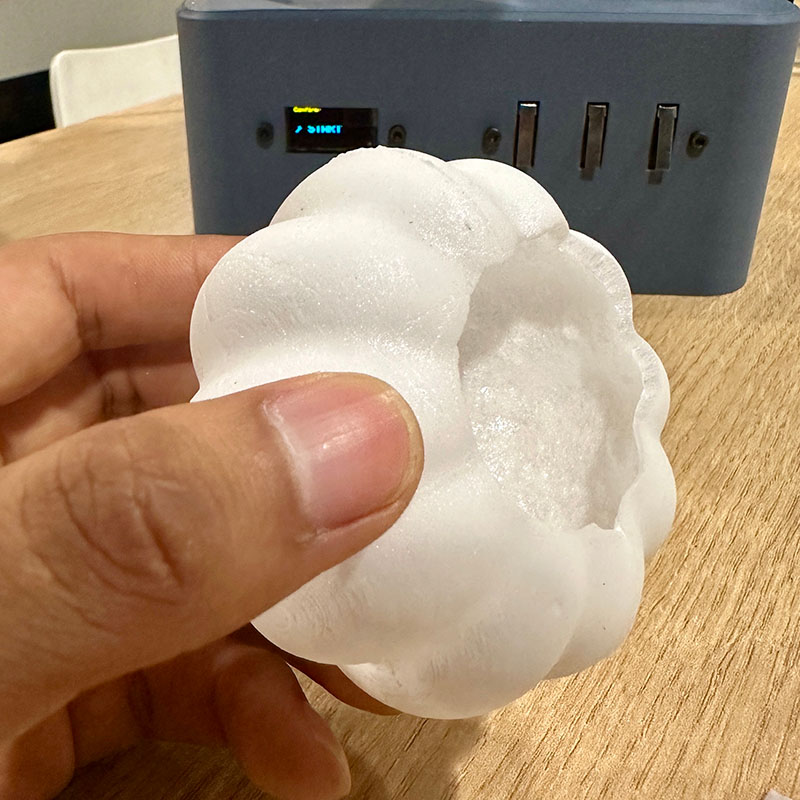
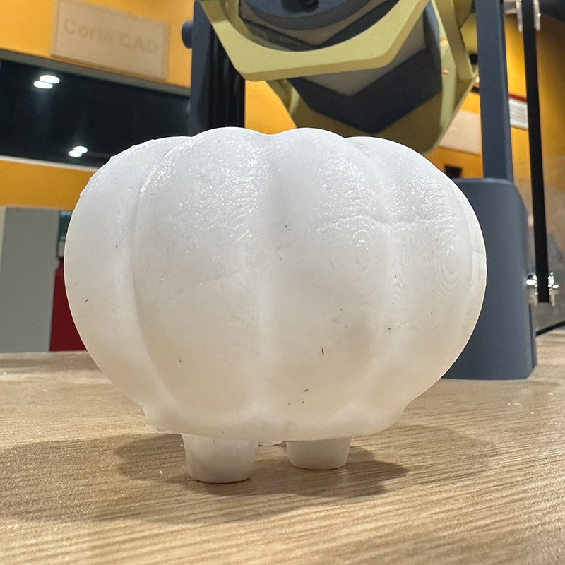
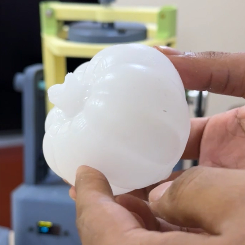
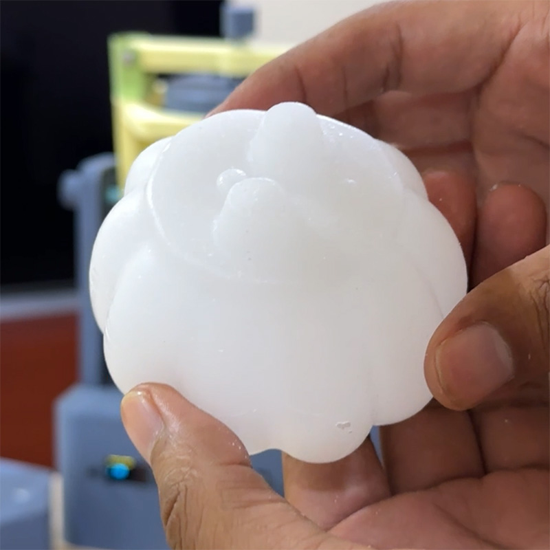
This is the result of testing different types of wax. The first two images show a wax that becomes fragile when solidified and the figure breaks easily. In the bottom two images, the figure is smoother and also more firm.
License
This project is shared under the CC BY-NC 4.0 Creative Commons Attribution-NonCommercial 4.0 International license.
Download:
Here you can download de printable parts of the machine and code: