Group Assignment
- Do your lab's safety training
- Showcase your lasercutter's focus, power, speed, rate, kerf, joint clearance and types
Showcase your lasercutter's focus, power, speed, rate, kerf, joint clearance and types
Please for group assignment details visit Anderson Zelarayan Web Page.
Do your lab's safety training
Here I want to extend some information regarding safety measures when using the laser cut. It is
important to
highlight that:
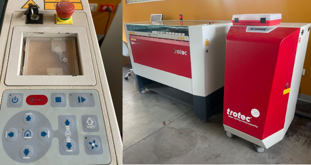
- The laser cut need to count with a filter system with high maintainance process
- To turn it on you need to use the key
- It is necessary to close the cover prior to calibrate the bed
- Once started, the bed goes down and you need to use the control system. Use the arrows to lift
the bed and proceed with calibration. You must move the bed around 20 to 15mm near to the laser
len
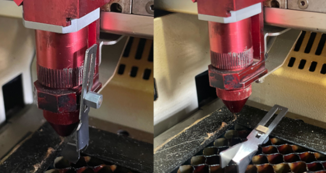
- Them,for this laser cut you'll need to use a calibration tool (similar to a key). This tool has
a to be located in a slot, like shown in the image below. Once there you need to use again the
up
arrow to slowly lift the bed until it touch the key and made it fall down. This prevent damaging
the machine
Individual Assignment
Cut something on the vinylcutter
I'm a star wars fan, so I decided to design a death star. I used corel drawn to design it. I
looked for a drawing to use it as a reference, searching in google images and found this
image. I started my draw following these steps:
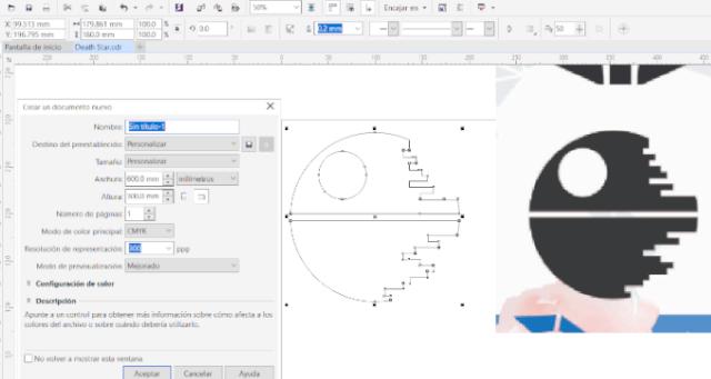
- I used Corel Draw X8, available at the fab lab ESAN.
- I open a new file choosing 600x300 mm as personalized drawing area. This
because I took the vynil cutter available measures.
- I made a screen shot of the image that I uses as reference and pasted it to corel
draw.
- I use ellipse and rectangle tools to make the drawing
- I use virtual segment removal
- I exported a first desing as SVG file, so it could be used in the vynil cutter
Vynil Cutter Use
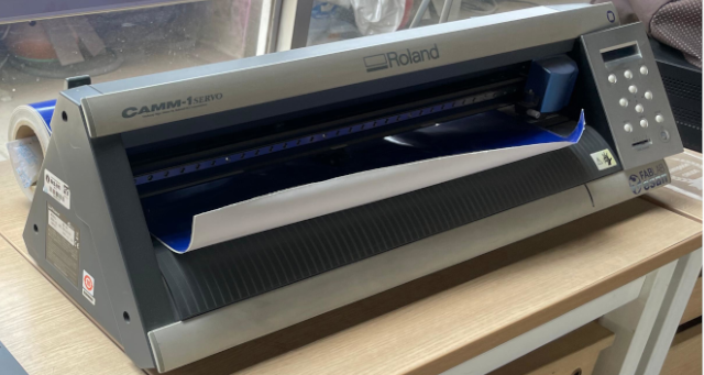 The lab has
a Roland machine GX24 (CAMM-1servo). I started following these steps:
- Connect the laptop with Ubuntu system
- We need to use Modes CE interface, that allow us to connect with the Vynil Cutter
- We need to turn on the machine, and select
Rolling this will make the machine to
move the cutter head to position at the begining point.
- At the back the machine has a lever. We need to lift it to roll the vynil, because the material
need to be stretched.
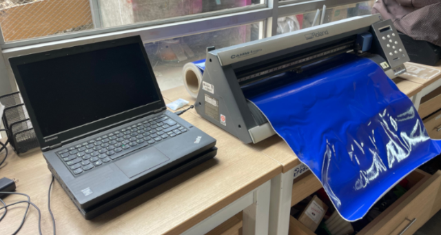
- Once everything is set, the vynil's screen will show the cutting longitude. At the begining was
set at 274mm, so I change it to 300mm to adjust it to my drawing requirement
- For the adjustment, the machine has four blank rectangles that appoint differnet distances, we
need to move a notch that is at the back and moved it to the distance needed for my draw. I
moved to 426 mm
- Once there, we open de Modes CE and follow these steps:
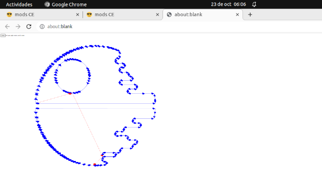
right click menu and look for the GX24 Machine (under Roland Machines)- Within the new screen we need to
open the port to select usb
- Then, we need to open the SGV file
select SGV files
- After we need to go to cut raster box and click
calculate
- The software will open the image of the cutter path.
- Close the image and go to
send file
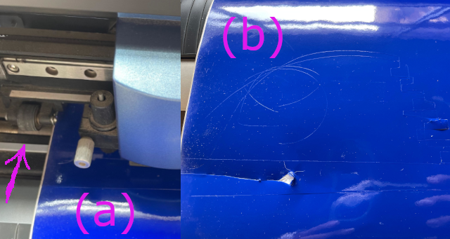
- I forgot to firmly fix the vynil roll and while doing the circle the cut move. The image bellow
shows that I forgot to set the vynil under the wheel, and the final result
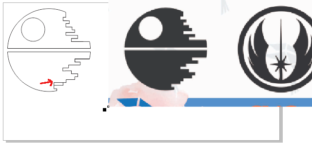
- I also noticed that I made a drawing mistake as shown in the folloing image, affecting the
final
result
- I tried again, but I made a mistake and didn't consider the first cut dimension, and the
second try the cut overlap the first. And also badly choose the output parameters Force: 20gf
and Speed: 2 cm, thus the machine did not make a clear cut
- I arrange the drawing and also scale it to 50%, following the same process I get the cut path
as
show below
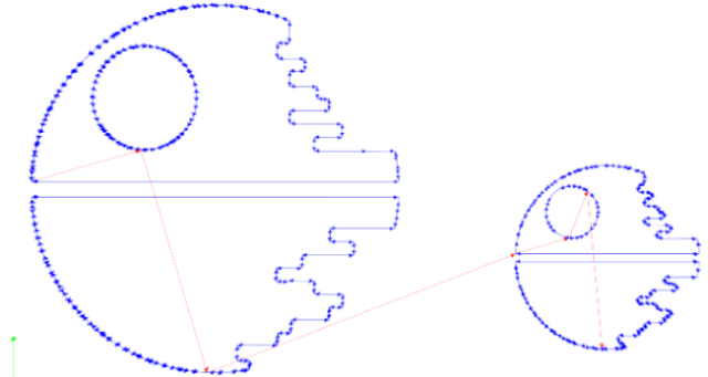
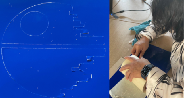
- I change the output parameters to Force: 120gf and Speed: 2 cm, the following picture
shows
the final result and when I started to stick the transfer tape
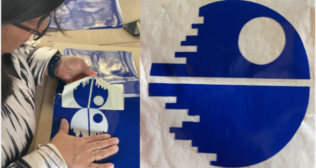
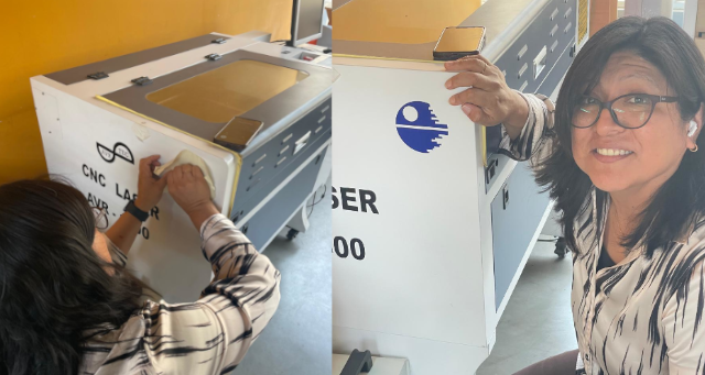
- Once I got the vynil sticker, I sticked into one of the fab lab's machine (another laser
cutter)
Parametric Construction Kit
We need first to find out the material kerf and then proceed with the kit parts design
Kerf Validation
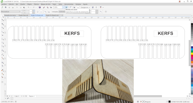
First I calculated the tolerance needed for an assembly, I cut a slight fit. For this, I drew
a first ruler using corel draw. Because the mdf is 3mm width, I prepare a ruler starting from 3.05mm
adding 0.05mm for each kerf up to 4mm.
However, the assembly did not fit adequately, it was loose, even when using 3.05mm when press fit
both rullers (see the following picture)
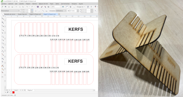
I fabricated a 2nd ruler, starting from 2.70mm adding 0.05mm for each kerf up to 3.65mm.
The assembly press fit adequately at 2.85mm (see the image below)
 To fabricate the rulers
using the trotec machine you need to:
-
Open file in Corel Draw
- The draw's lines need to have different colors, so we could differentiate those lines that
would be Cut and those that would be engraved
Black Lines (engrave) width:0.2mm
Red Lines width (cut):very thin
- Once the file is open, we need to consider the available cutting area and the material
dimensions(600x300mm)
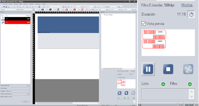
- Then,
Press Print
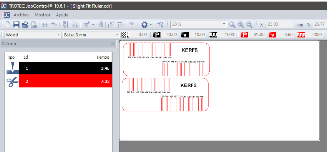
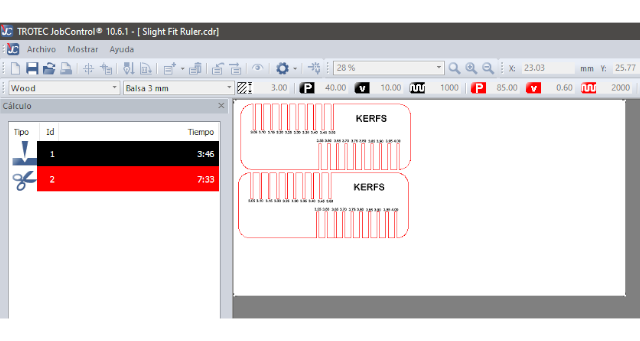
- The laser cut software will open (Trotec JobControl), at the left will appear the file name,
you'll need to click it, and move it to the cutting area
- At the bottom will appear a
Calculate buttom
- The software will provide time calculation for engraving and cutting
- At the right will appear a new window
Press Play buttom, and it will start cutting
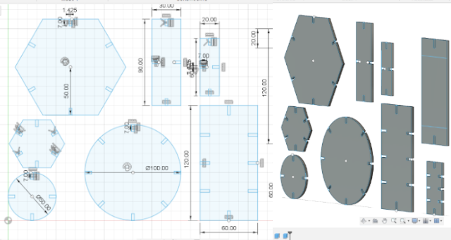
To create the construction kit, I used Fusion 360 to make some hexagonal, rectangular and circular
figures I modeled the pieces in 3D, first without a parametric desing, because I wasn't sure about
how to do it
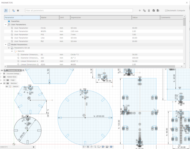
Then, I ask to my instructor how I can turn my desing to a parametric one. He told me that I have to
start over, so I can add some functions. After he explain me the basic about parametric design, I
set the following functions:
- To set tolerance
Width=2.85mm. Thus any of my rectangles to designs the press fit
would change, if I change material (mdf) width and tolerance
- To set press fit high, I set 2 different fit measures, applied accordingly to object size
Fit1=7mm for the smalless ones and Fit2=10mm for the bigger ones
- Then I set the smalless diameter for a circle that could be fabricated that allows manipulation
as
Circle=10mm. Thus, all the circles and hexagones were desing using it
- Finally I set the smalless line to desing a rectangle (when fabricated could allows manipulation)
as
line=10mm. Thus, all the rectangles were desing using it
- To distributed all the press fit rectangles I used functions that constrains its location, such
as
Coincident, Circular pattern, Rectangular pattern,
Mirror, and Offset
You can observe the final desing in the following photo:
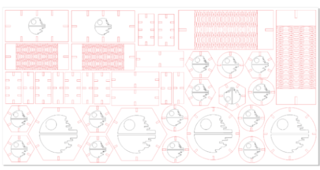
Then I exported the files to DXF format to imported in Corel Draw, that means to turn to a 2D process.
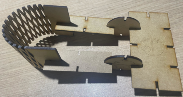
I decide to include the death star as a figure to engrave and a fabricate a flexible piece, I used a
pattern that my instructor share with me, then I fabricated them using laser cutting
To fabricate the paremtric kit I followed:
- When you press
Print You need to choose Preferences
- Set Cutting area
600x300mm
- Select material parameters
material: wood and material width: 3mm
- The parameters to engrave
Speed: 10, Power: 40 and Frequency: 1000Hz.
- The parameters to cut
Speed: 0.60, Power: 85 and Frequency: 2000Hz.
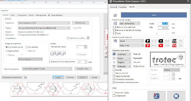
- I obtained 57.48 min to engrave and 46:12 min to cut
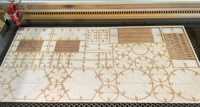
I obtained the pieces, but I have to made some changes on the flexible one, because I forgot to
delete a line.
- The first cut result>
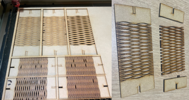
- I change the flexible piece to correct the desing and finally have a complete piece, because at
the begining
I forgot to delete a line, and during cutting the piece split in two
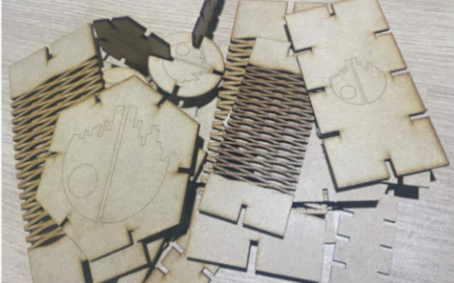
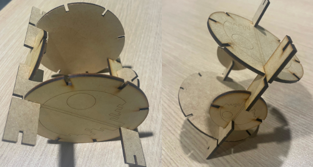
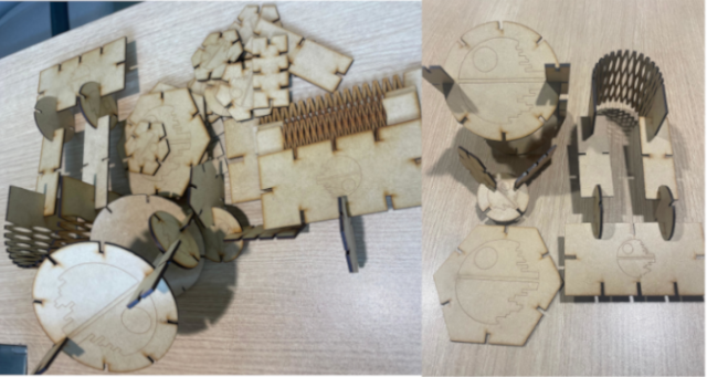
- I cut the pieces and try to unleash my imagination and build some structures.
Reflections
- We need to be careful with the width lines for cutting and engraving, taking into account To
engreve you'll need more that 0.2mm
- Use fusion 360 to create the parametric kit was more easy, because you can add kerfs rapidly
- You need to consider that Fusion 360 allows you to export to DXF, and not SVG
- You need to level the laser cut bed and consider that it could present imperfections, so you
need to select adequately your point of reference for leveling. Thus, you'll avoid that some
piece
did not get cut
You can get access to my death star SVG file here.
You can get access to my ruler file here.
You can get access to the first no parametric kit design in fusion 360 here.
You can get access to the real no parametric kit design here.
You can get access to the cdr file for laser cutting here.


 The lab has
a Roland machine GX24 (CAMM-1servo). I started following these steps:


 To fabricate the rulers
using the trotec machine you need to:


