WEEK 3
Computer-controlled cutting
Assignment:
Group Assignment:
- Characterize your lasercutter's focus, power, speed, rate, kerf, joint clearance and types.
Individual Assignment:
- Cut something on the vinylcutter.
- Design, lasercut, and document a parametric construction kit, accounting for the lasercutter kerf, which can be assembled in multiple ways, and for extra credit include elements that aren't flat.
This week I had a lot of fun cutting MDF, acrylic and vinyl. I tried out the cutting machines at the Fab lab Esan, including a Trotec Speedy 400, an AVR-1400, and a smaller one for vinyl cutting, a Roland CAMM-1. First, I did some tests to calculate the kerf; then I conducted tests varying the powerq and speed for both cutting and engraving; calculated tolerances for assembling with a certain fit and finally cut small pieces of a puzzle.
Group Assignment:
Those were the laser cutters we have in the lab, the AVR-400 and the Trotec Speedy 400. Both achieve similar quality, but the Trotec is significantly faster.
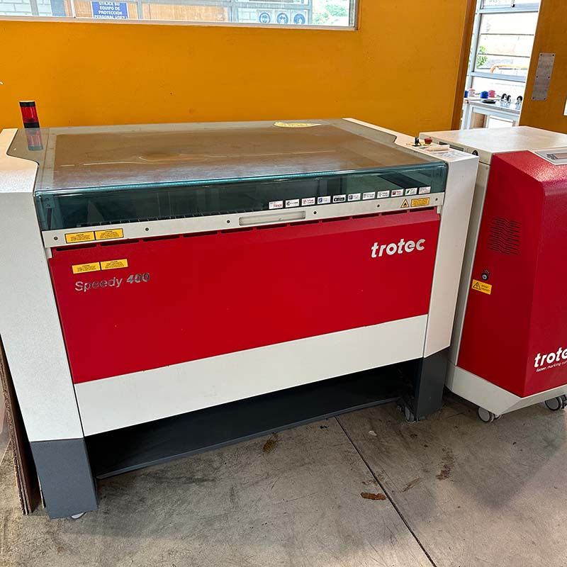
Trotec speedy 400
The main features of this cutter are as follows:
- This is a CO2 laser cutter and engraver.
- Maximum power of the CO2 laser 120 W
- Work area of 1016 x 610 mm
- Maximum work speed of 4.3 m/s.
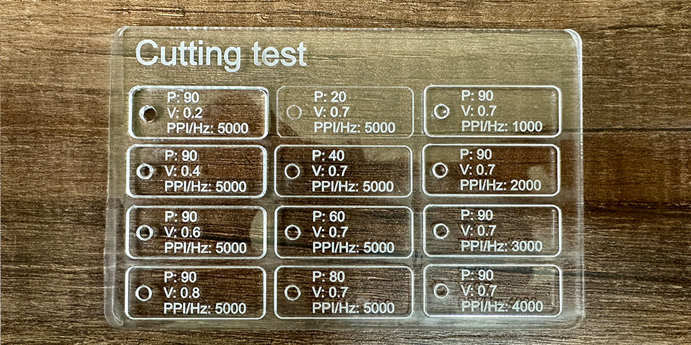
I conducted some cutting tests by varying the power, speed, and frequency. I used the lab's parameters for cutting 3mm acrylic as a base (power: 90, speed: 0.7, Hz: 5000). Currently, the lab is using two passes due to a technical issue, but for the tests, I did it in a single pass.
Using one single pass, only the first block was cut, which was tested at a speed of .2 m/s (see the following image). For this reason, two passes are being used.
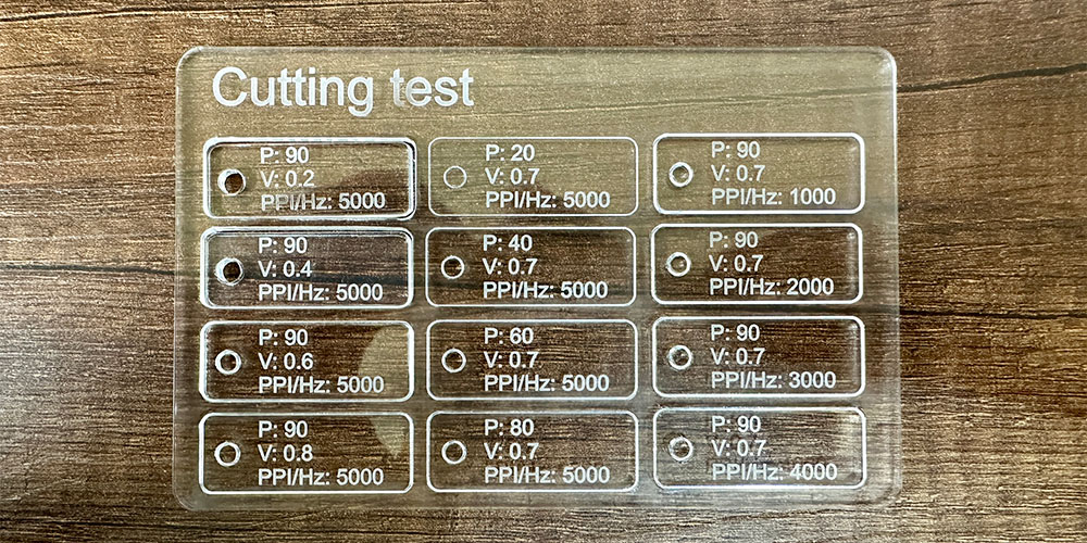
With two passes, more blocks are cut except those with power below 60.
To calculate the kerf in the cut, I conducted several tests cutting rectangles of different dimensions. Then, for each one, I calculated the difference between the value in the program and the actual value of the piece, obtaining a kerf of 0.30 mm. Considering this value in the design will improve the accuracy of the cut.
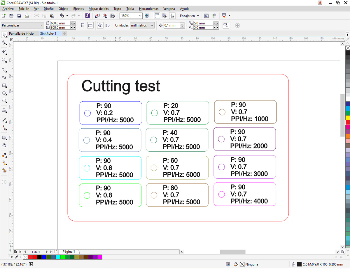
In the ESAN Fab Lab, the cutter is connected to CorelDRAW, so to perform the acrylic cutting test, I created the following drawing. It was necessary to change the color and thickness of each line to ensure the correct cutting profile is used. After this, you just have to press Ctrl-P as if you were printing something on paper, to open the cutter's software Job Control.
The cutting profiles can be defined in Job Control, and each of them is associated with a color. As shown in the following image, some parameters such as power, speed, frequency, and the number of passes can be varied.
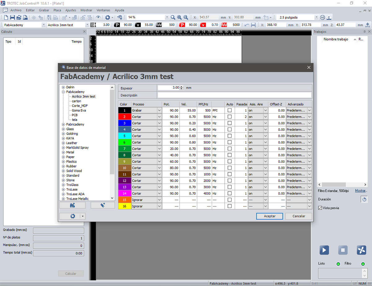
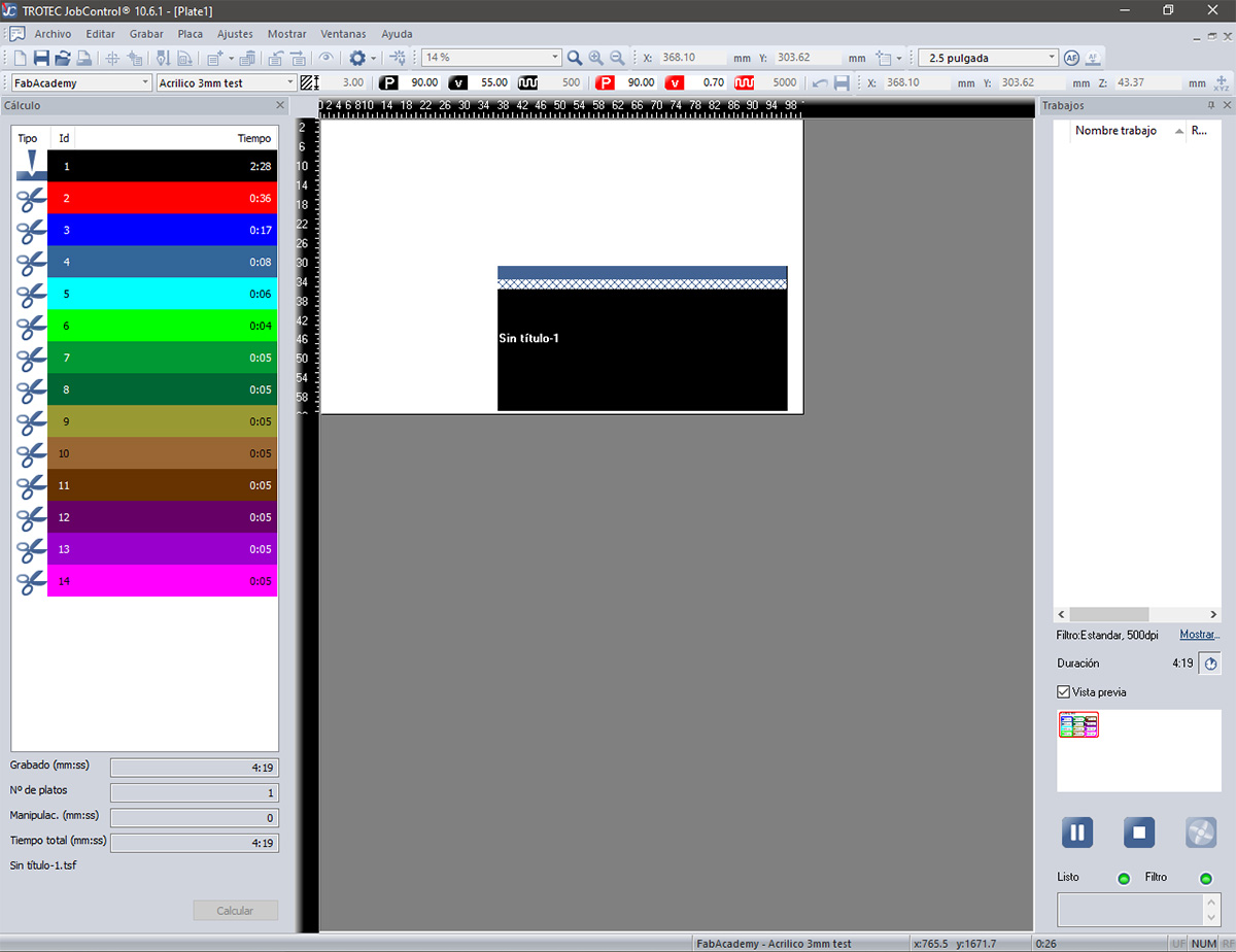
Also, from this software, you can calculate the time the entire job will take, as well as see how long each cut will take based on the color or profile used.
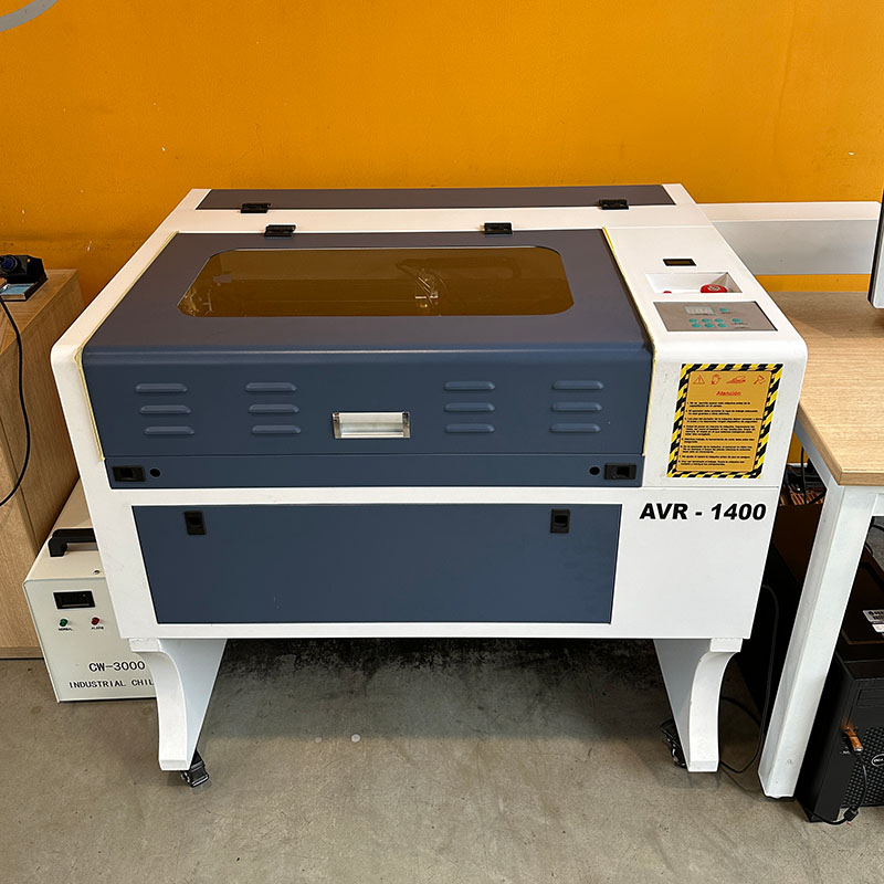
AVR-1400
The main features of this cutter are as follows:
- This is a CO2 laser cutter and engraver.
- Maximum power of the CO2 laser 100 W
- Work area of 600 x 400 mm
- Maximum work speed of 500 mm/s (engraving)
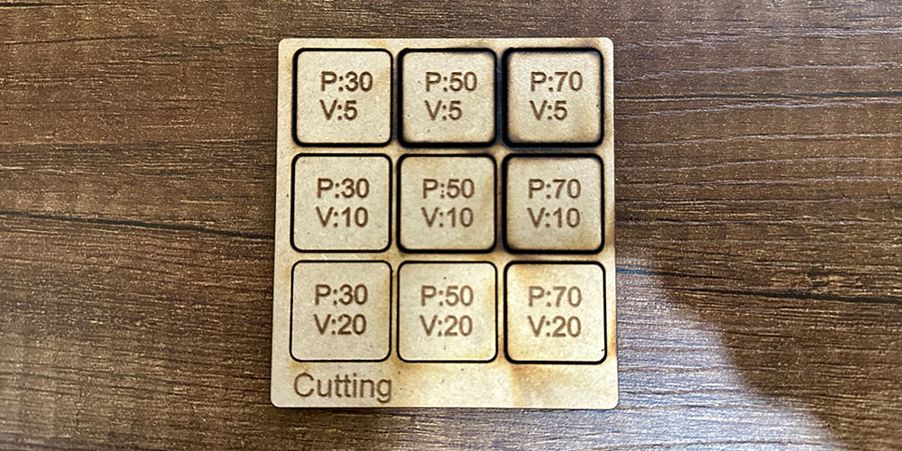
In this smaller cutter, I also conducted some cutting and engraving tests, but this time on 3 mm MDF. Here, I can adjust the speed from the cutter's user interface and the power with buttons on the machine itself.
In the following image, you can see the result of the cutting test. All managed to cut the square except for those with a power of 30 and a speed greater than 10. Also, in some cases, the power was too high or the speed too slow, resulting in wider and more burnt edges. Therefore, the ideal speed is between 10-20 mm/s, and the ideal power is between 50 and 60.
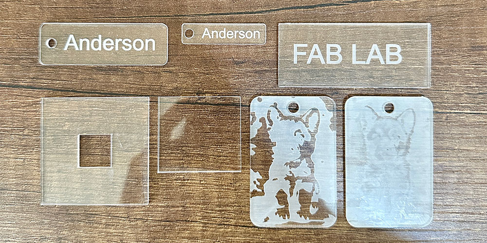
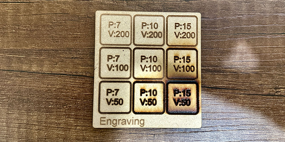
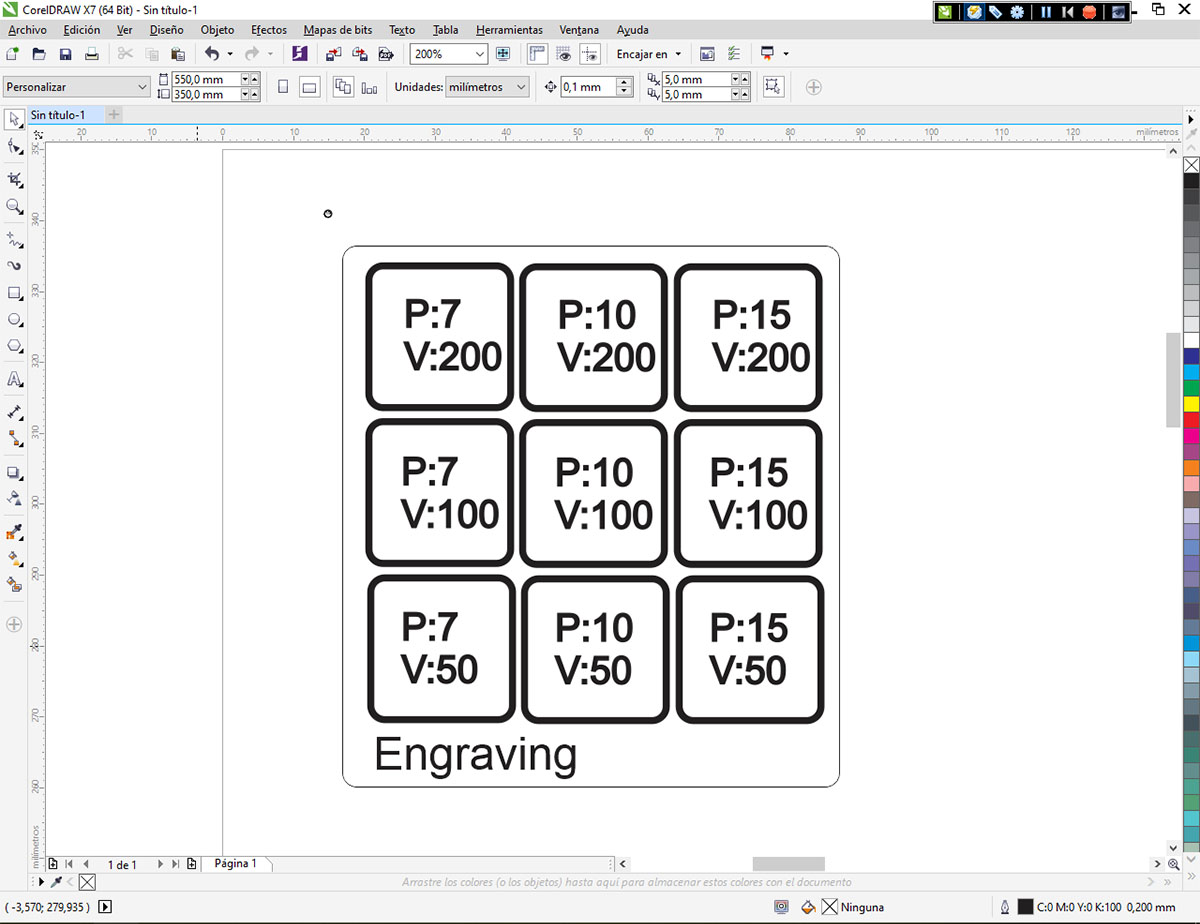
The engraving test was very similar to the cutting test, although engraving works with higher speeds and lower powers. In the following image, you can see that when the power is too high or the speed too low, the material burns too much and does not have a good quality finish. A good finish is obtained with a speed of 200 mm/s and a power of 10.
The calculation of the kerf is the same as that used for the acrylic cutting test. Several cuts were made in 3mm MDF, and the difference between the value in the plans and the actual value was calculated, resulting in a kerf of 0.10 mm.
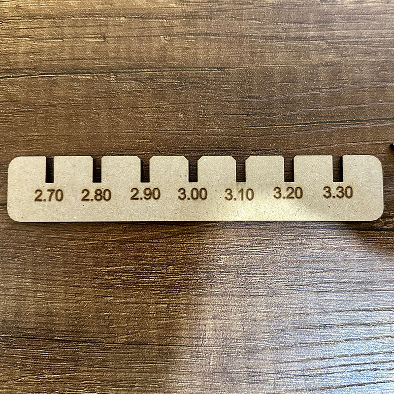
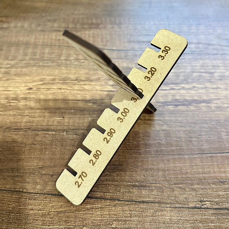
I also calculated the tolerance needed for an assembly with a slight fit. For this, I drew the following ruler and tested the assembly between its slots. I found a good fit using an increase of 0.10-0.20 mm.
This cutter is also connected to CorelDRAW, but with an additional plugin. The operation is quite similar to Trotec. Designs can be created directly in CorelDRAW or imported. The line thickness must be set to 'very thin' for cuts; the color is not relevant. For engraving, any thickness can be used.
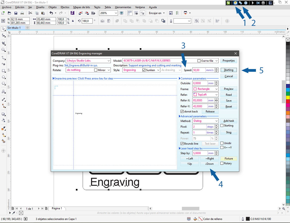
Then, you need to select the object or figure and click on the cutting icon (2) or the engraving icon (1). Next, a window will open where you can adjust the speed (3), move the laser's position (4), and start the operation (5), as shown in the following image. Note that there is no option for power adjustment because, on this machine, the power is set directly on the machine itself.
Individual Assignment:
Vinyl Cutting
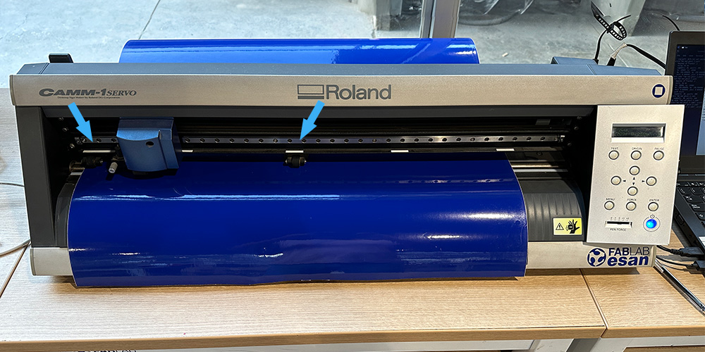
The first thing I did on the vinyl cutter was to place the vinyl and define the work area, as indicated by the blue arrows in the following image. This time, I cut out a small ghost that I designed last week when I learned how to use Inkscape.
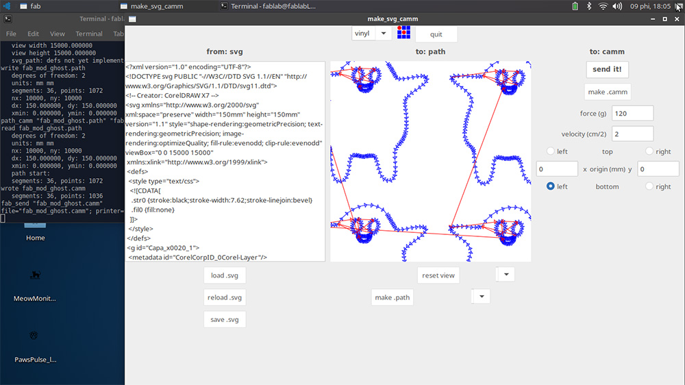
The image below shows the application used to control the vinyl cutter. It allows you to set the force and speed values and also displays the path the cutter blade will follow.
To make the cut on vinyl with the cutter, I followed these steps:
- Place the vinyl and select the work area.
- Open the application and load the file you want to cut (the file can be in PNG or SVG format).
- Select the material.
- Generate the path.
- Set the force in grams and the speed in cm/s.
- Send the cut.
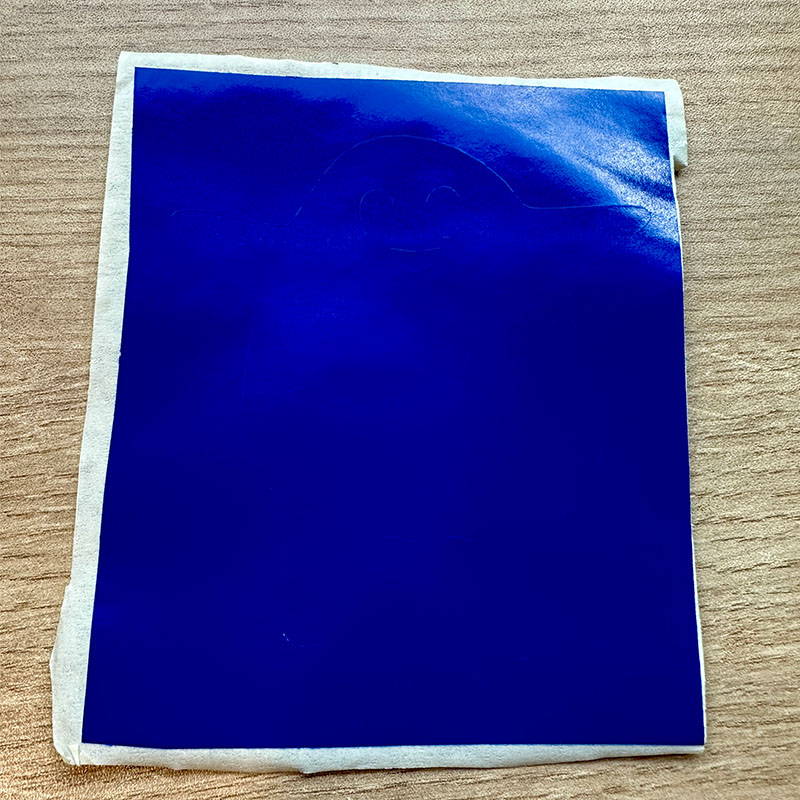
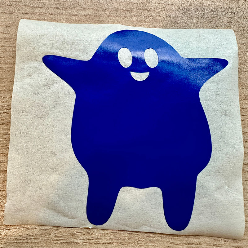
After completing the cut, you need to trim the vinyl area where the figure is located. Then, attach a transfer tape to the front surface of the vinyl. Remove the vinyl's backing and also the parts of the figure that are not part of the design; in this case, I removed the background, the eyes, and the mouth of the ghost.
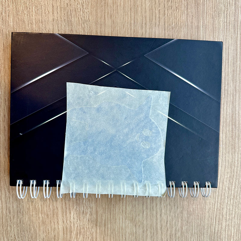
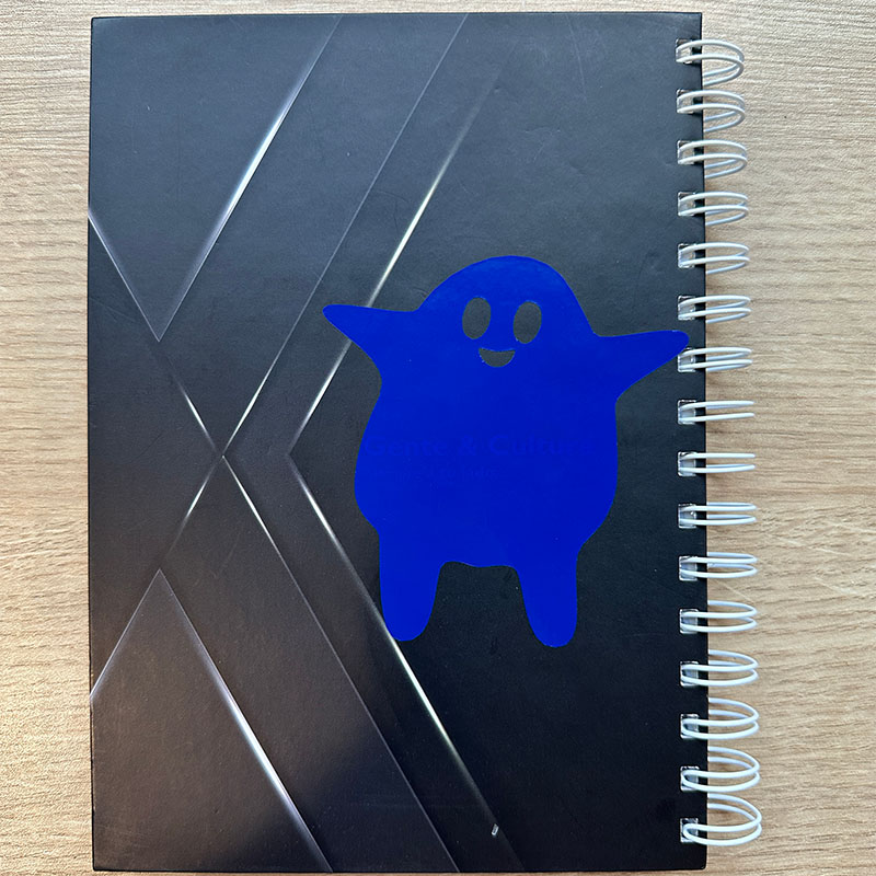
Finally, place it on the surface you want to customize and carefully remove the transfer tape.
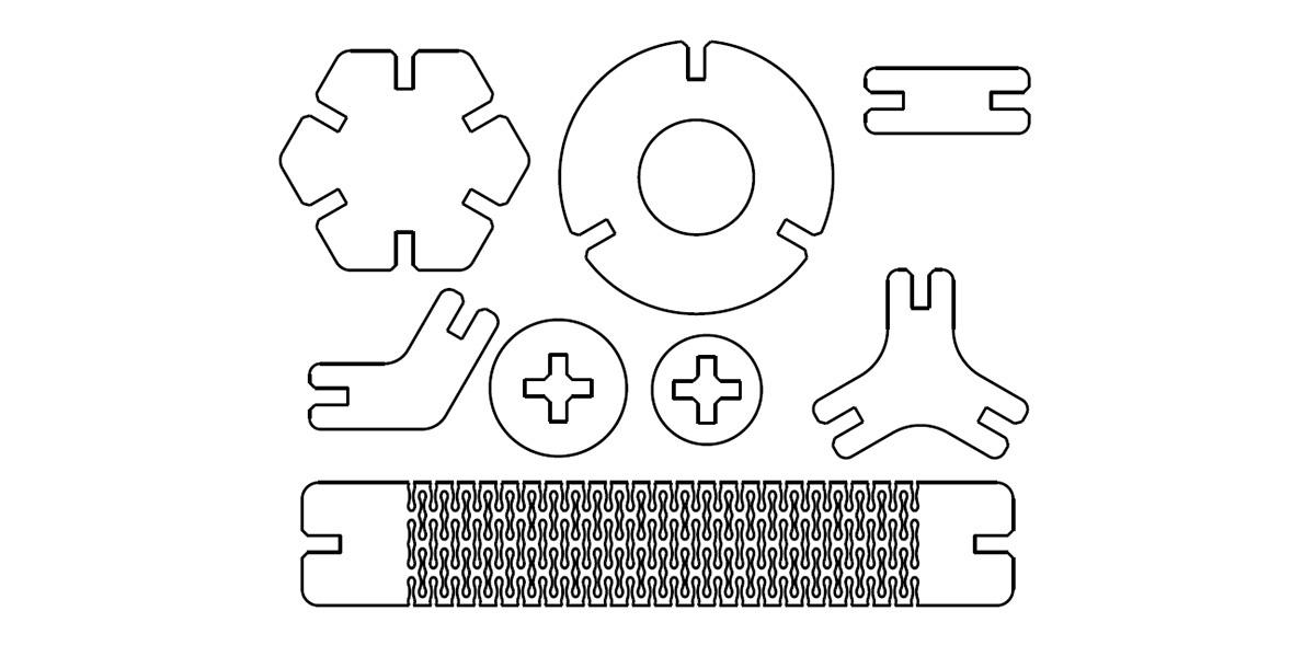
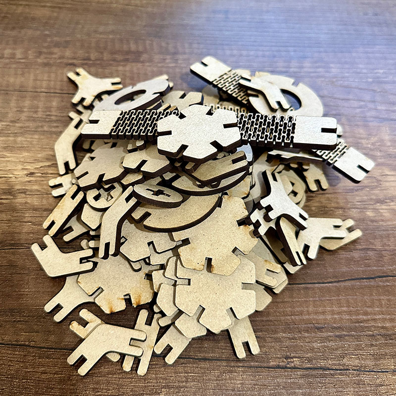
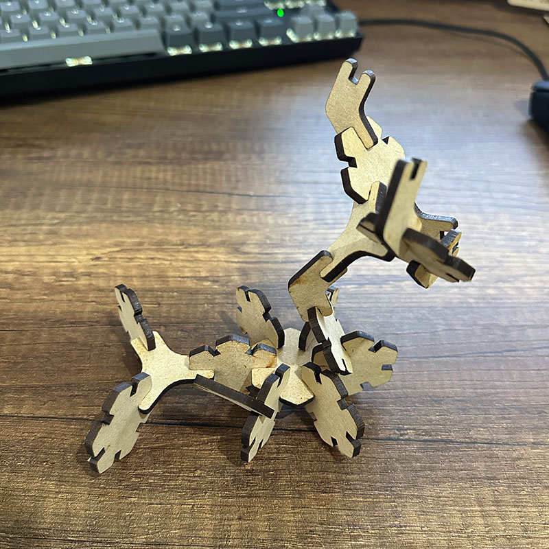
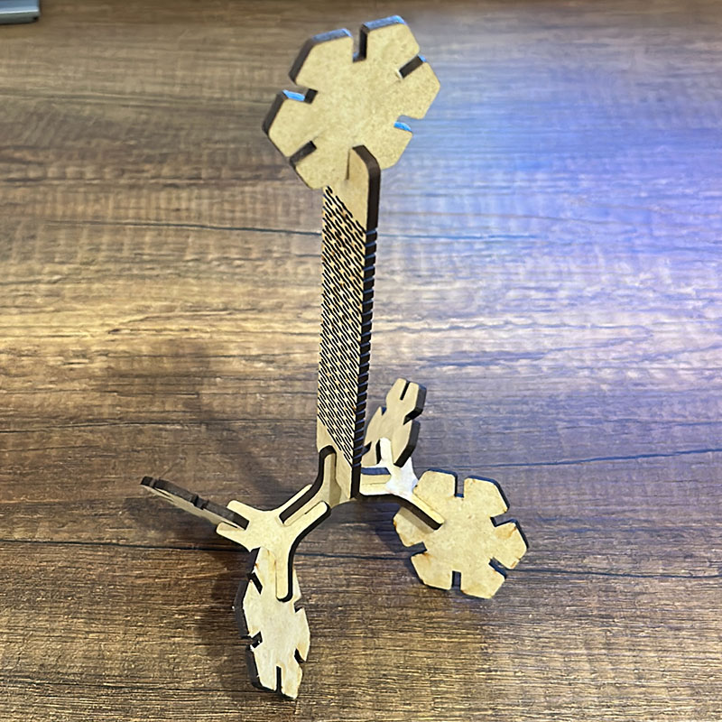
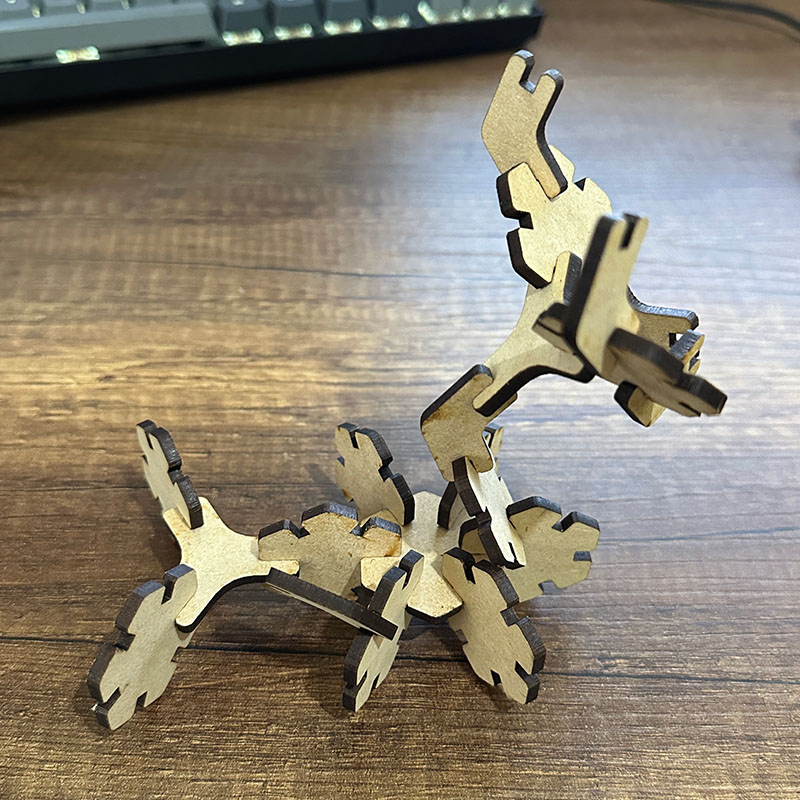
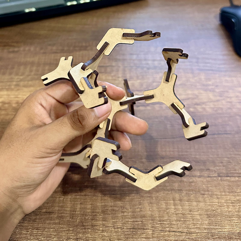
Parametric construction kit
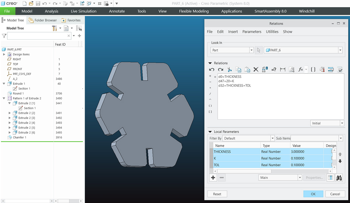
To create the construction kit, I used Creo to make some hexagonal figures and a flexible piece. What I did was model it in 3D and then I created a plan to extract the figures in 2D.
To make the pieces easy to modify, I added some parameters. Creo allows the creation of parameters of various types and also lets you establish relationships between them. I created three parameters: thickness, kerf (0.10 mm), and assembly tolerance (0.15 mm), which I calculated during the tests.
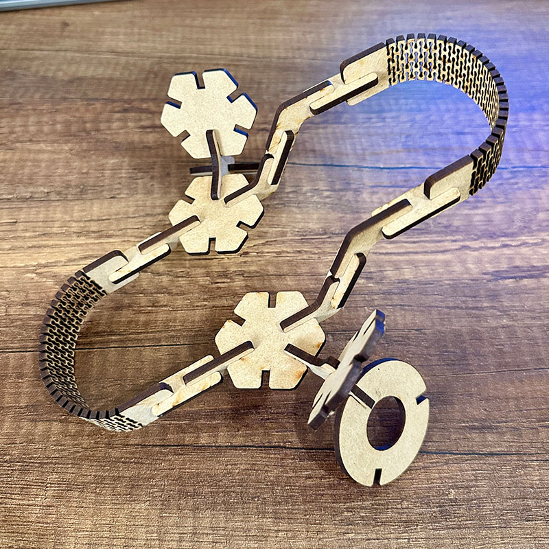
These are some structures that can be assembled with it.
Here you can download de files of the ghost and the parametric kit: