10 & 11th Week Assignment
Machine Design

Machine Design
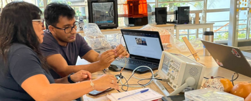
 We
reviewed different options, to work with, and decide to work on a machine that could draw some
geometric lines on "mates burilados"
Peruvians handmade traditional crafts. are produced - gourds carving with exceptionally detailed
representations of rural communities life. The gourds grow at the Peruvian coast, and they are sell as
touristic handicraft. Thus we though that some carved lines could be produce with a machine. We look for
examples, machines that could draw on irregular surfaces. Our instructor suggested to look for machines
that draw lines on eggs. My classmate was in charge of looking for similar projects, that share some
basic information on how to build them. He also found commercial options.
We
reviewed different options, to work with, and decide to work on a machine that could draw some
geometric lines on "mates burilados"
Peruvians handmade traditional crafts. are produced - gourds carving with exceptionally detailed
representations of rural communities life. The gourds grow at the Peruvian coast, and they are sell as
touristic handicraft. Thus we though that some carved lines could be produce with a machine. We look for
examples, machines that could draw on irregular surfaces. Our instructor suggested to look for machines
that draw lines on eggs. My classmate was in charge of looking for similar projects, that share some
basic information on how to build them. He also found commercial options.
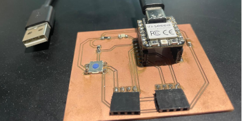
 It is a CNC machine design by JJRobots to draw basic figures on eggs.
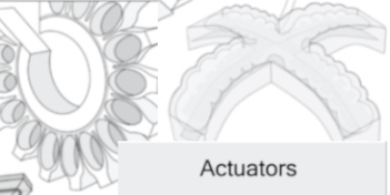
The key components in this design (as you can see in the picture) are:
It is a CNC machine design by JJRobots to draw basic figures on eggs.
The key components in this design (as you can see in the picture) are:
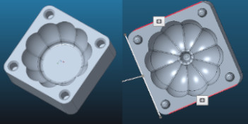
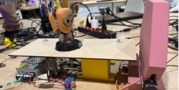
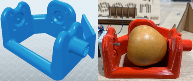
The major barrier with this design was that we need to use a DEVIA Board, that is not available locally.
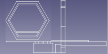
However, we decide to test the framework’s design, like shown in the image below.
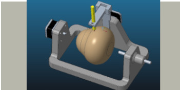
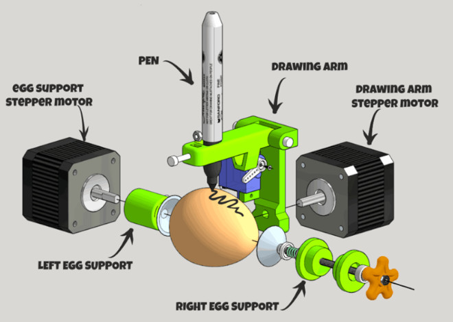
The EggBot Pro
This is a commercial device that allows to decorate different objects (that could be bigger that an egg).
It uses a solid aluminium main frame and 2 high-torque precision stepping motors to control rotation on X
axis and the movement on Y axis to generate the drawings. Also presents a pen lift mechanism using a
microservomotor. It uses a 16× microstepping to give a resolution of 3200 steps/revolution in both axes.
We noticed that this design uses NEMA 17 Stepper Motor Mounting Brackets, similar to the ones used in
some 3D printer modelss Which brings stepper motors stability within the whole mechanism. Thus, we decided to
include this commercial elements to design our main frame, instead of printing them, in order to ensure
stability, considering that rotation and Y movement at the same time could be challenging.
Engraving Easter Eggs with Laser machine
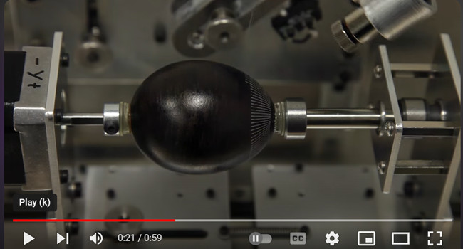 we found this variation of the egg-bot that includes a laser to engrave eggs,
created by untitled.house and that you can find in its Youtube channel. Instead of a pen, it uses a
water cooled 1 W laser diode. In this case the main frame is also made from aluminium.
we found this variation of the egg-bot that includes a laser to engrave eggs,
created by untitled.house and that you can find in its Youtube channel. Instead of a pen, it uses a
water cooled 1 W laser diode. In this case the main frame is also made from aluminium.
This could be considered for a second stage of our
project. In that case we will need to import the laser diode and test it with a different main frames
and components.
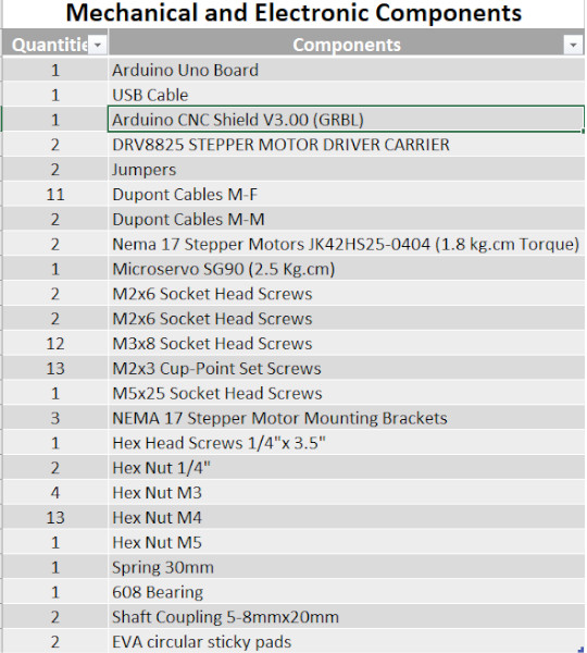
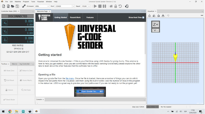
For this asignment we are allowed to use commercial devices, with our instructor support we select commercial boards
and devices that we can use for this machine design. In this case, to build this XYZ Axis Plotter (CNC machine),
all the mechanical and electronic devices that you’ll need to create this bot are:
 For this asignment
we are allowed to use commercial devices, with our instructor support we select commercial boards and
devices that we can use for this machine design. In this case, we will need to build XYZ Axis Plotter
(CNC machine), so we will need to control stepper motors. Also, we will require a microcontroler which
let us run GCode programing. As part of my contribution at this stage, I will provide devices's
technical
information, outlining the main characteristics that we will need to ensamble and programing it.
For this asignment
we are allowed to use commercial devices, with our instructor support we select commercial boards and
devices that we can use for this machine design. In this case, we will need to build XYZ Axis Plotter
(CNC machine), so we will need to control stepper motors. Also, we will require a microcontroler which
let us run GCode programing. As part of my contribution at this stage, I will provide devices's
technical
information, outlining the main characteristics that we will need to ensamble and programing it.
 In
our case
we
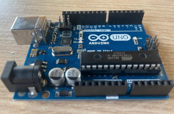
choose to use from the FabAcademy Inventory the Arduino Uno.This board, base on its data
sheet
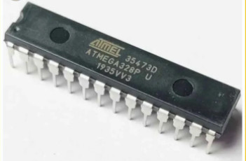
information, equipped with the well-known ATmega328P and the ATMega 16U2 Processor. It contains
everything needed to support the microcontroller; simply connect it to a computer with a USB
cable, with a AC-to-DC adapter or battery to get started. (AC power plugs: used to connect devices to
wall outlets. DC power Connector
jacks:used to connect devices to power supplies or batteries). USB connectors: used to provide
power to and transfer data between devices. One of the major feature of Uno Wifi is the
support of OTA (Over-the-air) programming for Arduino sketches and for Wifi firmware. Recommended
In
our case
we
choose to use from the FabAcademy Inventory the Arduino Uno.This board, base on its data
sheet
information, equipped with the well-known ATmega328P and the ATMega 16U2 Processor. It contains
everything needed to support the microcontroller; simply connect it to a computer with a USB
cable, with a AC-to-DC adapter or battery to get started. (AC power plugs: used to connect devices to
wall outlets. DC power Connector
jacks:used to connect devices to power supplies or batteries). USB connectors: used to provide
power to and transfer data between devices. One of the major feature of Uno Wifi is the
support of OTA (Over-the-air) programming for Arduino sketches and for Wifi firmware. Recommended
Arduino Uno has:
| Item | Description |
|---|---|
| Input Voltage (recomended) | 7-12 V |
| Input Voltage (limit) | 6-20 V |
| Power Consumption | 130 mA (sleepmode 80mA) |
| PCB Size | 53.4 x 68.6 mm |
| Weight | 0.025 Kg |
| RAM | 8 MB instruction, 12 MB data |
| Operating Conditions | Min 40 °C (-40°F) and Max 85 °C ( 185°F) (VIN) Input voltage 6-20 V Imput voltage form USB connector 5.5V |
| Product Code | A000133 |
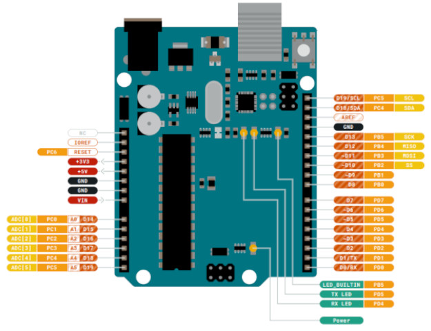
The Main Processor running at up to 20 MHz. Most of its pins are connected to the external headers, however some are reserved for internal communication with the USB Bridge coprocessor. omes preprogrammed with a bootloader that allows you to upload new code to it without the use of an external hardware programmer.
| Item | Description |
|---|---|
| Microcontroller | ATmega328P |
| Architecture | Advanced RISC |
| Operating Voltage | 2.7V to 5.5V |
| Flash Memory | 32KB. |
| SRAM | 2KB |
| Clock Speed | 16MHz |
| Digital I/O Pins | 14, (2 serial communication - 2 external interrupts) |
| Analog Input Pins | 6 |
| Timer/Counter Pins | 3 |
| Crystal Oscillator Pins | 2 |
| EEPROM | 1KB |
| DC Current per I/0 | 20 mA |
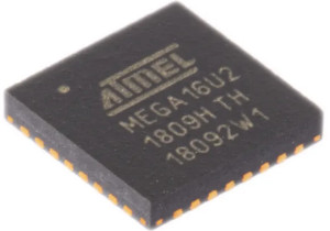
| Item | Description |
|---|---|
| Processor | ATmega 16U2 |
| Architecture | RISC |
| Operating Voltage | 2.7 - 5.5V |
| Operating Frecuency | 8 Mhz at 2.7V & 16MHz at 4.5 V |
| Operation Temperature | Industrial (-40°C to +85°C) |
| Data Memories | 16KB on In-System Self-Programmable Flash |
| EEPROM | 512 |
| SRAM | 512 |
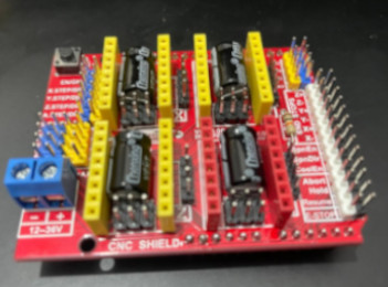 In our case we
choose to use from the FabAcademy Inventory the Arduino CNC Shield V3.00.This board, base on its data sheet
information, uses opensource firmware on Arduino to control 4 stepper motors using 4 pieces of A4988
Stepper
Motor driver breakout board, together with ArduinoUno, we can build all kinds of robotics, linear motion
project or projects including CNC routers, laser cutters and even pick&place machines. It uses e
software
called GRBL. Arduino Uno that takes G-Code commands via Serial and turns the commands into motor
signals.
In our case we
choose to use from the FabAcademy Inventory the Arduino CNC Shield V3.00.This board, base on its data sheet
information, uses opensource firmware on Arduino to control 4 stepper motors using 4 pieces of A4988
Stepper
Motor driver breakout board, together with ArduinoUno, we can build all kinds of robotics, linear motion
project or projects including CNC routers, laser cutters and even pick&place machines. It uses e
software
called GRBL. Arduino Uno that takes G-Code commands via Serial and turns the commands into motor
signals.
CNC Shield has:
| Item | Description |
|---|---|
| Input voltage: | 12-36V |
| Motor drivers: | Supports up to 4 stepper motors |
| Stepper motor driver: | Compatible with A4988/DRV8825 motor drivers |
| Power supply: | One terminal block is available for connecting the external power supply |
| Pin headers: | Expansion headers for adding additional functionality such as limit switches, end stops, and spindle control |
| Compatibility: | Compatible with the GRBL firmware and other popular CNC software |
Osoyoo web, provides this information, and a guideline for hardware installation.
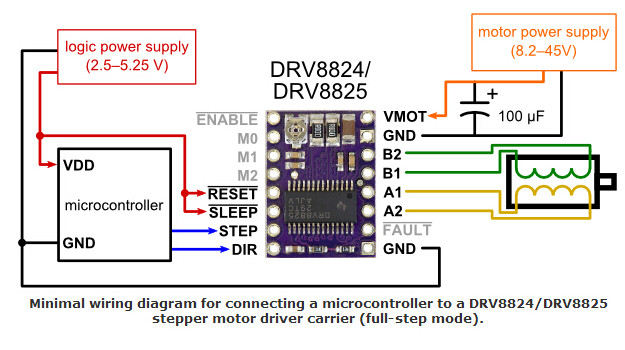 The DRV8825
provides an integrated motor driver solution for printers, scanners, and other automated equipment
applications. The device has two H-bridge drivers and a microstepping indexer, and is intended to
drive
a bipolar stepper motor. The output driver block consists of N-channel power MOSFET’s configured as
full
H-bridges to drive the motor windings. The DRV8825 is capable of driving up to 2.5 A of current from
each output (with proper heat sinking, at 24 V and 25°C).
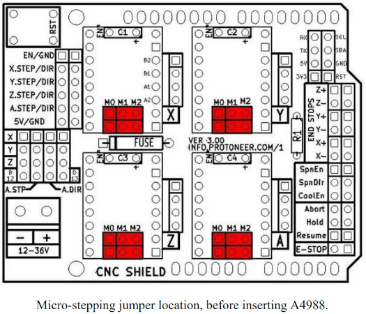
A simple STEP/DIR interface allows easy interfacing to controller circuits. Mode pins allow for
configuration of the motor in full-step up to 1/32-step modes. Decay mode is configurable so that
slow
decay, fast decay, or mixed decay can be used. A low-power sleep mode is provided which shuts down
internal circuitry to achieve very low quiescent current draw. This sleep mode can be set using a
dedicated nSLEEP pin. You can find the datasheet here
The DRV8825
provides an integrated motor driver solution for printers, scanners, and other automated equipment
applications. The device has two H-bridge drivers and a microstepping indexer, and is intended to
drive
a bipolar stepper motor. The output driver block consists of N-channel power MOSFET’s configured as
full
H-bridges to drive the motor windings. The DRV8825 is capable of driving up to 2.5 A of current from
each output (with proper heat sinking, at 24 V and 25°C).
A simple STEP/DIR interface allows easy interfacing to controller circuits. Mode pins allow for
configuration of the motor in full-step up to 1/32-step modes. Decay mode is configurable so that
slow
decay, fast decay, or mixed decay can be used. A low-power sleep mode is provided which shuts down
internal circuitry to achieve very low quiescent current draw. This sleep mode can be set using a
dedicated nSLEEP pin. You can find the datasheet here
 This
product offer a shaft motion consists of discrete angular movements of
essentially uniform magnitude when driven from a sequentially switched DC power supply, such being
describe at Electromate.com . It works with digital signals. One digital pulse to a
step
motor drive or translator causes the motor to increment one precise angle of motion. As the digital
pulses increase in frequency, the step movement changes into continuous rotation. So we can test it
at
full motion. It has windings in the stator and permanent magnets attached to the rotor. It provides
fixed mechanical increments of motion (referred as steps, and generally specified in degrees). They
are
considered ideal for applications that require quick positioning over a short distance, Allowing the
use
of an open-loop controller, which simplifies machine design and lowers cost compared to servo motor
systems.
This
product offer a shaft motion consists of discrete angular movements of
essentially uniform magnitude when driven from a sequentially switched DC power supply, such being
describe at Electromate.com . It works with digital signals. One digital pulse to a
step
motor drive or translator causes the motor to increment one precise angle of motion. As the digital
pulses increase in frequency, the step movement changes into continuous rotation. So we can test it
at
full motion. It has windings in the stator and permanent magnets attached to the rotor. It provides
fixed mechanical increments of motion (referred as steps, and generally specified in degrees). They
are
considered ideal for applications that require quick positioning over a short distance, Allowing the
use
of an open-loop controller, which simplifies machine design and lowers cost compared to servo motor
systems.
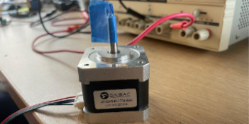
This device holds a NEMA denomitation, that accounts for the National Electrical Manufacturers Association acronym. This mean that is standirized motor size, including designations that can help as learn more about the size and capability of practically any particular motor. Step motors are categorized by NEMA frame size, such as "size 11" or "size 23" or “size 34”. NEMA 17 stepper motors are those that have a 1.8 degree step angle (200 steps/revolution) with a 1.7 x 1.7 inch faceplate. They typically have more torque than smaller variants, such as NEMA 14 and have a recommended driving voltage of 12-24V. These steppers are also RoHS compliant (acronym for "Restriction of Hazardous Substances." A European Union directive that regulates the use of certain hazardous substances in electrical and electronic equipment - EEE).
| Item | Description |
|---|---|
| Model No. | JK42HS25-0404 |
| Step Angle | 1.8° |
| Motor Length | 25 (L)mm |
| Current/Phase | 0.4 A |
| Resistance/Phase | 24 Ω |
| Inductance/Phase | 36mH |
| Holding Torque | 1.8 kg.cm |
| # of Leads | 4 |
| Detent Torque | 75 g.cm |
| Rotor Inertia | 20 g.cm |
| Mass | 0.15 Kg/td> |
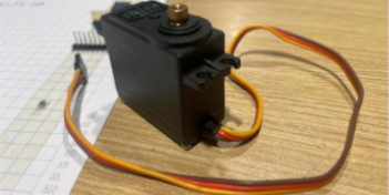
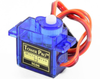 Tiny and
lightweight (it will fit in small places) with high output power. Servo can rotate approximately 180
degrees (90 in each direction), and works just like the standard kinds but smaller. You can use any
servo code, hardware or library to control these servos. With feedback & gear box. In our case it
came with a 8 different horns models (arms). We decided to use the one thah only have one arm.
Regarding arms positions, it is necessary to highlight:
Tiny and
lightweight (it will fit in small places) with high output power. Servo can rotate approximately 180
degrees (90 in each direction), and works just like the standard kinds but smaller. You can use any
servo code, hardware or library to control these servos. With feedback & gear box. In our case it
came with a 8 different horns models (arms). We decided to use the one thah only have one arm.
Regarding arms positions, it is necessary to highlight:
You can find the datasheet here .
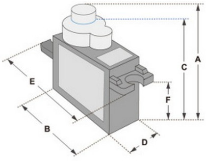
| Item | Description |
|---|---|
| A (mm) | 32 |
| B (mm) | 23 |
| C (mm) | 28.5 |
| D (mm) | 12 |
| E (mm) | 32 |
| F (mm) | 19.5 |
| Speed (Sec) | 0.1 |
| Torque (kg-cm | 25 |
| Weight (g) | 14.7 |
| Voltage | 4.8-6 |
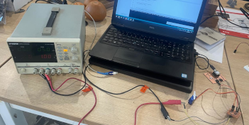
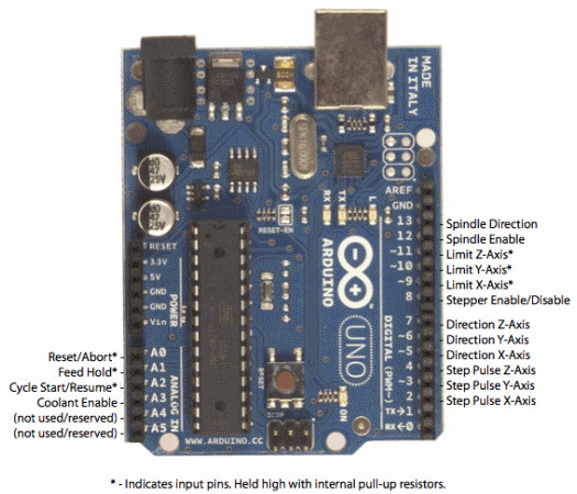
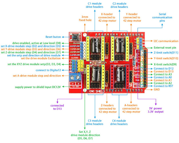
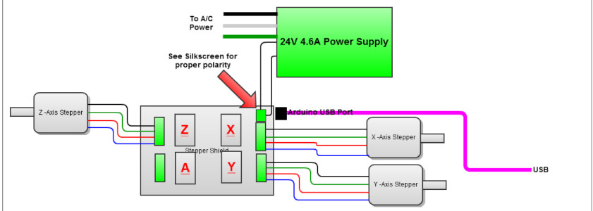
The purpose is to connect steppers motor to CNC Shield board as the below block diagram, that shows
the CNC Shield connected to 3-stepper motor:
| Item | Description |
|---|---|
| PWM Microstepping Stepper Motor Driver | Built-In Microstepping Indexer / Up to 1/32 Microstepping |
| Multiple Decay Modes | Mixed / Slow / Fast |
| Operating Supply Voltage Range | 8.2-V to 45-V |
| Reference Output | 2.5-A at 24 V and TA = 25°C |
| Reference Output | Built-In 3.3-V |
| Body Size | 9.70 mm × 6.40 mm |

Wellcome to the process of trying to make almost something