13th week Assignment
Molding and Casting
Molding and Casting
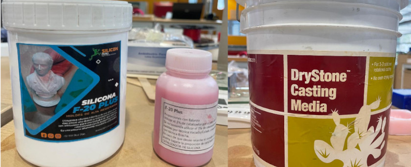
In this case materials available are:
Please for safety data sheet visitthis Web Page.
Please for safety data sheet visitthis Web Page.
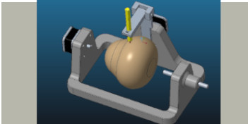
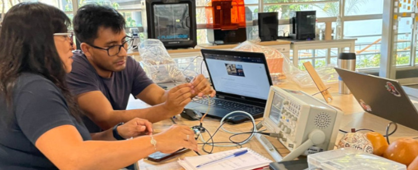
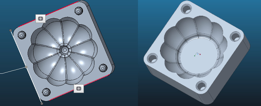
First, it is neccesary to decide about the design of the figure/object to fabricate. In our case, as a group we decide to test something related with our group machine, to fabricate a pumpink. This because it could allow us to test rounded surfaces that could be fabricated each half with different technique. One half with 3D printing and the other half with CNC milling
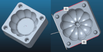
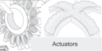
At first we considered a desing with a 80mm radio (see figure a) and produce two halfs negative molds one part for CNC miling and and the other one for 3D printing process. The idea was to reproduce one figure with two different source of positive molds, so the comparison could be easier. However, we did not notice that for setting figure's dimensions, we need to considered CNC miling machine's volume. This because the endmill have a limitation regarding milling height (25mm maximun). Thus we have to change punkin's radius to 50 mm (see figure b)

Then, we also get confused and generated possitive molds for milling and printing. That would be useful only if we manted to reproduce the mold directly form a flexible material. However, the object will have to be reproduce from cement, so we have to desing again
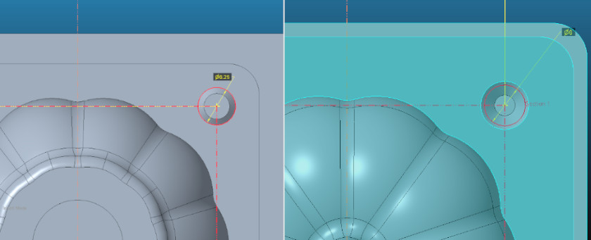 Because we need to machine two negative molds that will cast a complete figure, each of them need to
have alignned pins to allow a modls fitting. Hence, we considered four (4) pins for each mold part,
and to secure fitting, with 0.25mm tolerance.
Because we need to machine two negative molds that will cast a complete figure, each of them need to
have alignned pins to allow a modls fitting. Hence, we considered four (4) pins for each mold part,
and to secure fitting, with 0.25mm tolerance.
You can see in the image, that tolerance was consider at bottom of the pin (height) and for diameter. Thus, fitting between male-female pins will no present any problems.
 Final design
consideration have to be focus on negative-molds walls:
Final design
consideration have to be focus on negative-molds walls:
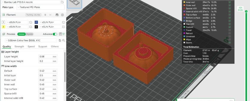
For the 3D printing we use a Bambu Lab P1S, it took 90 minutes printing in high quality. You can appreciate printing configuration in the following picture.
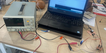
For the CNC samll scale milling we use Modela MDX20 and we follow this process
Open FabModules programSet XY Axis originSee image below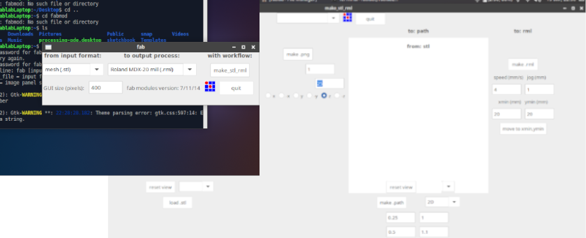
Manually calibrate Z Axis
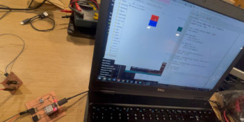
Load .stl file.
Set position in our case we inverted the image in -Z axis
Press make png buttom Press Make pathPress Make mrlSend fileThe image below shows settings before milling 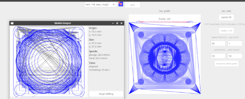
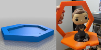
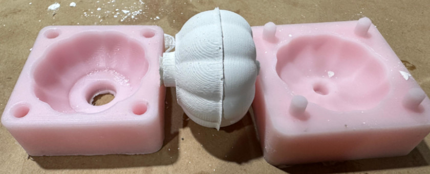
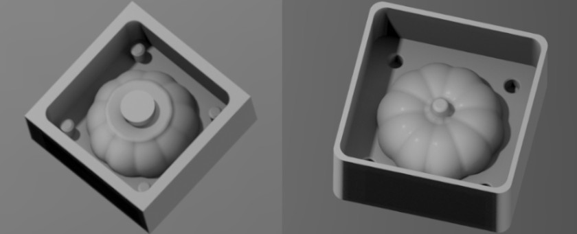
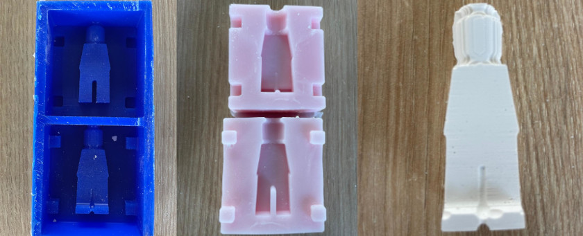
The image below shows the final negative molds in both technologies 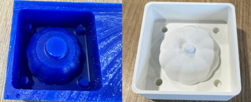
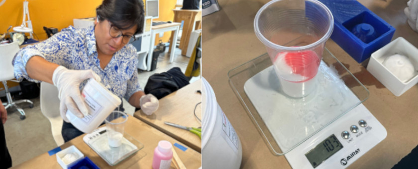
Once we have both molds (3D printed and Milled) we iniciate the process to obtain both molds following this steps:


To obtain the final figure we follow this process:


We compare some features of the processes in order to conclude which one presented better results
| Criterion | CNC Miling | 3D Printing |
|---|---|---|
| Machining Time | Roughing: 35 min Finising: 45 min | Printing time: 90 mins |
| Suface Finish | Medium quality with 1/8" end-mill (can achieve very smooth using smaller diameter) | High quality using 0.90 layer height (may require post-processing if use larger layer heights) |
| Design Complexity | Limited by the accessibility of cutting tools and the geometry of the machine | Allows complex geometries without additional cost, ideal for molds with fine details or intricate internal structures |
Please you can find editable (.prt) file and machining (.stl) files for 3D printing and CNC milling here.
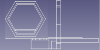
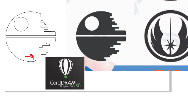
I select to fabricate a figurine base on lego figures. I based my design on a web site in order to maintain some relative dimensions. This web site show some dimensions reference to fabricate a wood-made figure, you can visit it here.
The first process was 2D design based on a figure dimension reference, as you can see in the following picture

Then, I need to create the volumetric form using extrude and revolve function on Fusion, like the show below
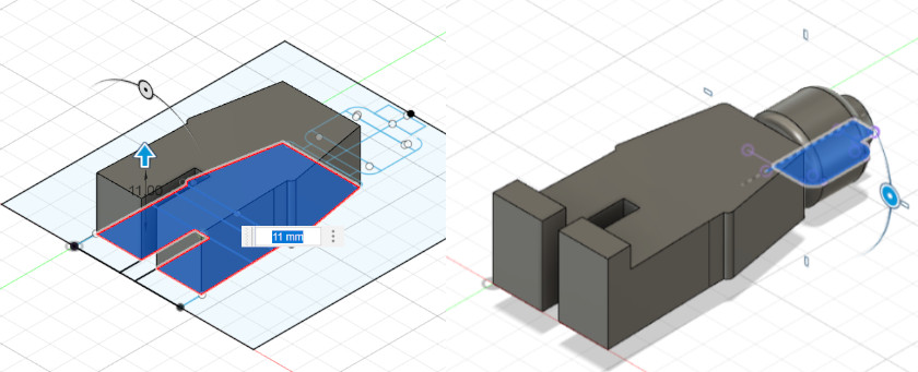
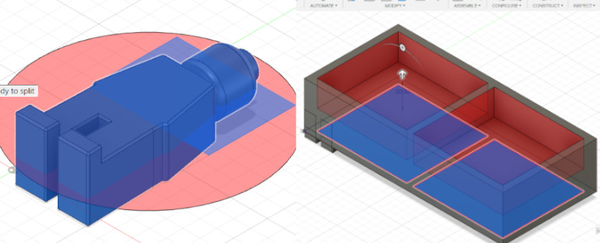
Finally, I split the figure (creating components), created the volume that represent wax dimensions, and relocate both figures into the two boxes and create "."stl" files to machine.
You can download desing files here.
For the CNC small scale milling we need to differenciate two processes that need to be developed within a waterfall schema, meaning that exist interdependancy between them.
| Rough Milling | Finishing Milling |
|---|---|
| Low quality surface finish | Quality of the surface finish is the top priority |
| Roughing end mills don't need cutters with very sharp edges, taking high chip load | Finishing end mills need sharper cutters, allowing low chip load to achieve a smoother finish. |
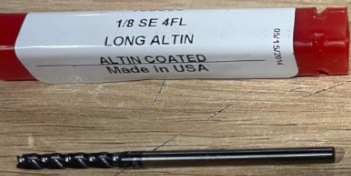
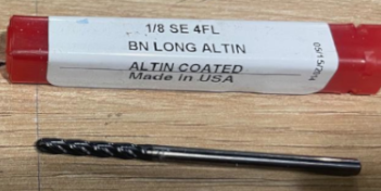
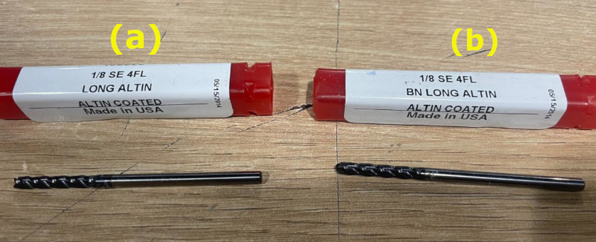
| Roughing process will be machined with 1/8" long-singled square endmill | Finishing process will be machined with 1/8" ball-nose endmill |
 |
 |
| End Mill overlaping could be set lower (aproximately 20%) | End Mill overlaping need be set close to 100% to improve the surface quality |
For both (rough and finish) CNC small scale milling processes I used Modela MDX20 and followed this process
Open FabModules programSet XY Axis originSee image belowManually calibrate Z Axis
Load .stl file.
Set position in our case we inverted the image in -Z axis
Press make png buttom 
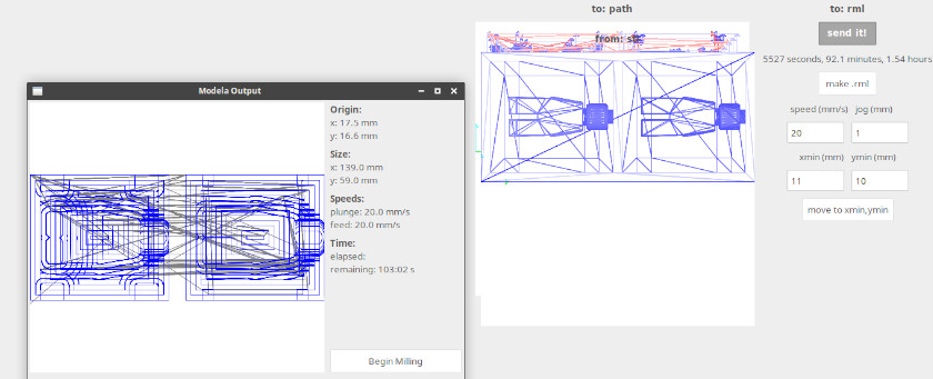
Overlapingsettings need to be stablished (25% for rough nd 60 for finish)Press Make pathPress Make mrlSend fileThe image below shows settings before milling The image shows the first machining that took 103 minutes
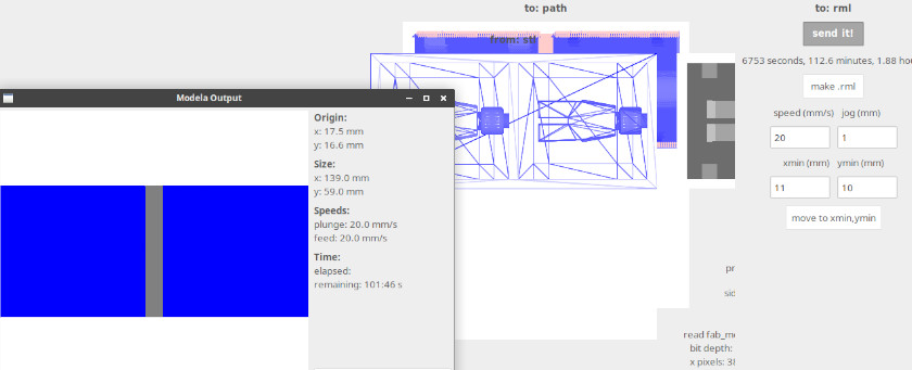
This picture shows second machining stage that took 101 minutes
Once we have both molds (3D printed and Milled) we iniciate the process to obtain both molds following this steps:
Somethings to highligh for this procees is:

Wellcome to the process of trying to make almost something