15th week Assignment
Interface and Application Programming
Interface and Application Programming
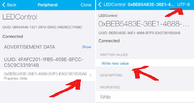
In this case, we decide to compare three (03) options available. One where we can use a third party developed interfaceand two that allow us to generate interfases:

Properties WriteHex (default option)UTF-8 String Properties write and there
you'll must click on Write new value 1 to turn the
LED on, and 0 to turn it off
#include <BLEDevice.h>
#include <BLEUtils.h>
#include <BLEServer.h>
#include <BLE2902.h>

#define LED_PIN D0 // Cambia el pin según la conexión de tu LED
#define SERVICE_UUID        "4fafc201-1fb5-459e-8fcc-c5c9c331914b"
#define CHARACTERISTIC_UUID "beb5483e-36e1-4688-b7f5-ea07361b26a8"

BLEServer* pServer = NULL;
BLECharacteristic* pCharacteristic = NULL;
bool deviceConnected = false;

class MyServerCallbacks : public BLEServerCallbacks {
	void onConnect(BLEServer* pServer) {
	  deviceConnected = true;
	};

	void onDisconnect(BLEServer* pServer) {
	  deviceConnected = false;
	}
};

class MyCallbacks : public BLECharacteristicCallbacks {
	void onWrite(BLECharacteristic *pCharacteristic) {
	  std::string value = pCharacteristic->getValue();

	  if (value.length() > 0) {
		if (value[0] == '1') {
		  digitalWrite(LED_PIN, HIGH); // Encender el LED
		} else if (value[0] == '0') {
		  digitalWrite(LED_PIN, LOW); // Apagar el LED
		}
	  }
	}
};

	void setup() {
	  Serial.begin(115200);
	  pinMode(LED_PIN, OUTPUT);

	  BLEDevice::init("LEDControl");
	  pServer = BLEDevice::createServer();
	  pServer->setCallbacks(new MyServerCallbacks());

	  BLEService *pService = pServer->createService(BLEUUID(SERVICE_UUID));
	  pCharacteristic = pService->createCharacteristic(
			  BLEUUID(CHARACTERISTIC_UUID),
			  BLECharacteristic::PROPERTY_WRITE
				);

	  pCharacteristic->setCallbacks(new MyCallbacks());

	  pService->start();
	  BLEAdvertising *pAdvertising = pServer->getAdvertising();
	  pAdvertising->start();
	  Serial.println("Esperando la conexión Bluetooth...");
	}

	void loop() {
	  if (deviceConnected) {
		// Puedes realizar otras tareas mientras está conectado
	  }
	  delay(1000); // Espera para no saturar el procesador
	}
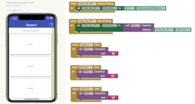
In the following image you can observe the process
You can download the Codehere.
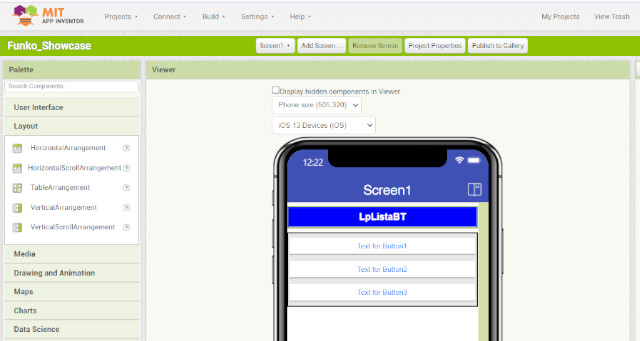
Device selector
and 3 buttoms for output's actions to be reflected on a LCD
Anger Face, Sorprised Face and Tired Face
User Interface and Layout. The first one allows
you to add the components that you decide to include in your interface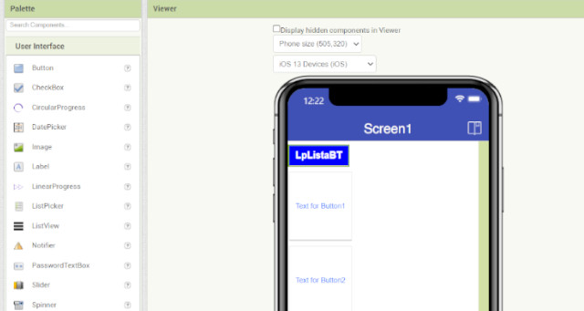
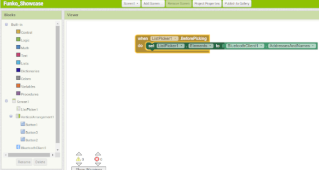
Connect < Emulator or run the app
on your cellphone (You'll need to download App Inventor throught your
Playstore or AppStore) following the app instructions to scan a QR or using
a number code to connect with the platform and get access to your developed App.

You can download the Codehere.
#include <Wire.h>
#include <Adafruit_GFX.h>
#include <Adafruit_SSD1306.h>

#define SCREEN_WIDTH 128 // OLED display width, in pixels
#define SCREEN_HEIGHT 64 // OLED display height, in pixels
#define OLED_RESET -1 // Reset pin # (or -1 if sharing Arduino reset pin)

Adafruit_SSD1306 display(SCREEN_WIDTH, SCREEN_HEIGHT, &Wire, OLED_RESET);

int sensorPin = 27;    // analog input pin RP2040 pin 27
int val = 0;  // variable to store the value coming from the sensor

unsigned int ADCValue;

void setup() {

  display.begin(SSD1306_SWITCHCAPVCC, 0x3C);
  delay(2000);
  display.clearDisplay();
  display.setTextColor(WHITE);

  Serial.begin(9600); // initialize serial communications

  pinMode(28,OUTPUT);
}

void loop() {

	display.clearDisplay();
  val = analogRead(sensorPin); // read the value from the sensor
  val = map(val,0, 1023, 0, 255);
  Serial.println(val); // print value to Serial Monitor
  analogWrite(28,val);

  display.setTextSize(2);
  display.setCursor(0, 28);
  display.print(val);

  display.display();
  delay(300);
}

import processing.serial.*;

Serial myPort;  // Create object from Serial class
static String val;    // Data received from the serial port
int sensorVal = 0;

void setup()
{
  size(720, 480);
  noStroke();
  noFill();
  String portName = "COM18";// Change the number (in this case )
  to match the corresponding port number connected to your Arduino.

  myPort = new Serial(this, portName, 9600);
}

void draw()
{
  if ( myPort.available() > 0) {  // If data is available,
  val = myPort.readStringUntil('\n');
  try {
   sensorVal = Integer.valueOf(val.trim());
  }
  catch(Exception e) {
  ;
  }
  println(sensorVal); // read it and store it in vals!
  }
 background(0);
  // Scale the mouseX value from 0 to 640 to a range between 0 and 175
  float c = map(sensorVal, 0, width, 0, 400);
  // Scale the mouseX value from 0 to 640 to a range between 40 and 300
  float d = map(sensorVal, 0, width, 40,500);
  fill(100, c, 0);
  ellipse(width/2, height/2, d, d);

  fill(255);
  textSize(30);
  text("Sensor Value: "+ sensorVal, 10, 40);


  fill(200);
  textSize(50);
  text("Sensor Value: "+ sensorVal, 10, 100);

 fill(150);
 noStroke();
 rect(100,200,c,20);
}
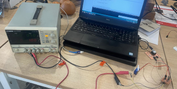
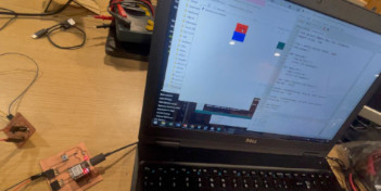
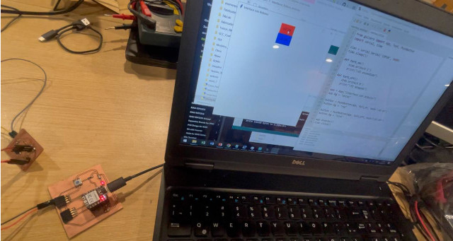
In the following image you can observe the process and interface result. We develop
an interface to show a square and a circle that increase their size regarding the imput
they recieve form the magnetic field detector. The images below shows how the interface
change when a magnet is expose from different distances

You can download the Code for Arduino Ide and Processing here.
I decided to use thonny to develop my interface. Thonny is a software that runs Python IDE.
 And to develop interface you can dowload a specific package (a sort
of plug in) call Guizero, that allows you to get access to specific coding libraries.
Guizero is designed to allow new learners to quickly and easily create Grapfic User
Interfaces for their programs. This library could be use to be run also on Phyton IDE, and
you can download it using the following instructions like it is explained here.
We also need to install another library Pyserial to get access for the serial port and
you can download it using the following instructions like it is explained here.
Further, I used guizero to develop my interface, but using Thonny, following this steps:
And to develop interface you can dowload a specific package (a sort
of plug in) call Guizero, that allows you to get access to specific coding libraries.
Guizero is designed to allow new learners to quickly and easily create Grapfic User
Interfaces for their programs. This library could be use to be run also on Phyton IDE, and
you can download it using the following instructions like it is explained here.
We also need to install another library Pyserial to get access for the serial port and
you can download it using the following instructions like it is explained here.
Further, I used guizero to develop my interface, but using Thonny, following this steps:
#define led 26

void setup() {
  // put your setup code here, to run once:
  pinMode(led, OUTPUT);
  Serial.begin(9600);
  digitalWrite(led, LOW);
}

void loop() {
  // put your main code here, to run repeatedly:
  if(Serial.available()>0){
	char option = Serial.read();
	if(option == '1'){
	  digitalWrite(led, HIGH);
	}
	else{
	  digitalWrite(led, LOW);
	}
  }
}
Go to Tools, Manage Packages,
Search for "guizero" and click on install

Go to Tools, Manage Packages,
Search for "pyserial" and click on install
from guizero import App, Text, PushButton
import serial, time

xiao = serial.Serial('COM30', 9600)
time.sleep(1)

def turn_on():
	xiao.write(b'1')
	print("LED encendido")

def turn_off():
	xiao.write(b'0')
	print("LED apagado")

app = App("Interface con Arduino")
app.bg = "white"

button = PushButton(app, turn_on, text="LED ON")
button.bg = "red"

button = PushButton(app, turn_off, text="LED OFF")
button.bg = "blue"

app.display()
xiao.close()
Play buttom on Thonny and the interface will appear in
your computer screen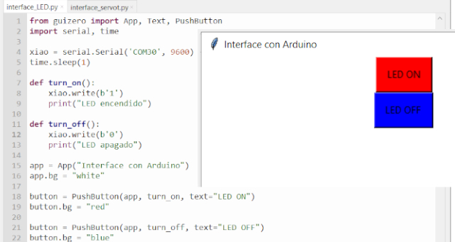
You can download the Arduino Ide and Thonny Programing files here.
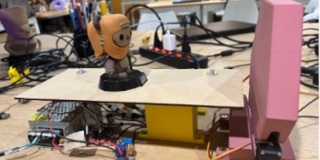
In the following video you can observe the final result when controlling the LED
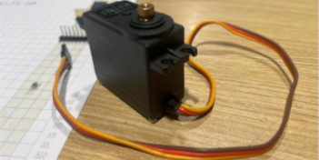
We used the same LED configuration but changing the code to control a microservo SG90
#include <Servo.h>


Servo myservo;  // create servo object to control a servo
// twelve servo objects can be created on most boards

void setup() {
	  Serial.begin(9600);
}

void loop() {
	  Serial.print("Procesos de Fabricacion Digital");
	  Serial.println(" Arduino Mega");
}
from guizero import App, Text, PushButton
import serial, time

xiao = serial.Serial('COM30', 9600)
time.sleep(1)

def turn_on():
		xiao.write(b'1')
		print("Servo 180")

def turn_off():
		xiao.write(b'0')
		print("Servo 0")

app = App("Xiao Interface")
app.bg = "white"

button = PushButton(app, turn_on, text="Servo 180")
button.bg = "red"

button = PushButton(app, turn_off, text="Servo 0")
button.bg = "blue"

app.display()
xiao.close()
Play buttom on Thonny and the interface will
appear in your computer screen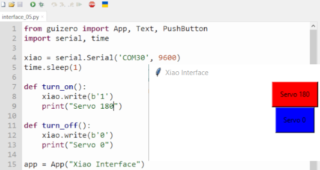
You can download the Arduino Ide and Thonny Programing files here.
In the follorwing video you can observe the final result when controlling the ServoMotor

Wellcome to the process of trying to make almost something