W17 Applications and implications
For my Final Project
For my Final Project

Propose a final project masterpiece that integrates the range of units covered, answering:
Your project should incorporate 2D and 3D design, additive and subtractive fabrication processes, electronics design and production, embedded microcontroller interfacing and programming, system integration and packaging. Where possible, you should make rather than buy the parts of your project Projects can be separate or joint, but need to show individual mastery of the skills, and be independently operable
 As a Funko Pop collector, kind of bubble head toys. I
have problems of storage and showcase them, due to the high value of some of the items.Those unique
and valuable items need to be protected, and avoid damages due to their exposure and manipulaton
whihch increase their risk of sufaring any physical damage. Thus, I'm looking for a way to showcase
some funkos, but reducing their level of physical exposure.
 Hence,
rather than acquiring or fabricating a simple shelf like the one shown in
this picture, that does not allow showcasing special items. I want to develop modular
hexagon
shelves, that could fit togehter simulating a hidden wall. The idea is to build a first hexagon
with a mobile top, when actioning it the top will open, activating a platform where the Funko
will be place and will move forward to showcase the toy. Thus, the toy will be stored adequately
and only when activating the shelf, it will appear.
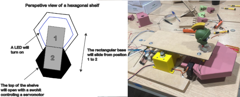
The following image tried to provide a description of the functioning process of each 3D printed hexagon. The shelve could be closed and then could be actioned, the hexagon's top will open and a rectangular platform could slides to showcase a funko
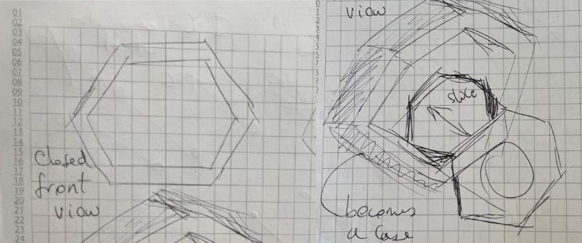
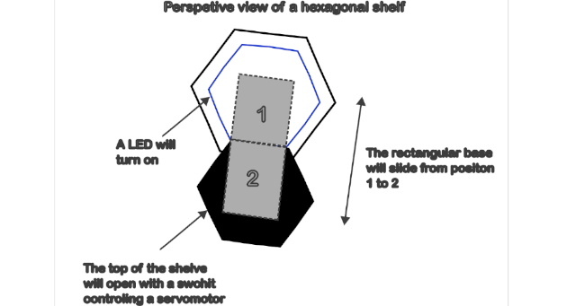
I also develop 2D graphic representation of the prototype I want to develop, that bring and explanation aobut how will function using inkscape. The idea is similar to a Cukoo clock functioning system, actrivating it and showing the toy, and then close it and hide it again
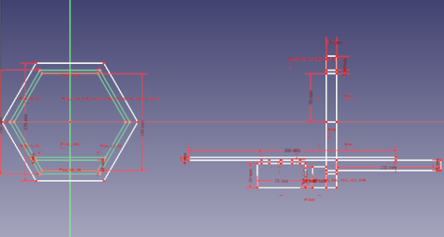
And another 2D graphic representation using FreeCad that shows front and side views
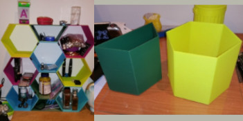 I visited some 3D printing designs repositories like thingiverse looking
for hexagon shelves models, and found two that I think could be useful. The first are big
hexagon sehlves,
functioning in a modular way, the couple forming some kind of big shelve that could be ensamble.
The problems with the design is that it seems very slim and it would need some kind of frame to
contain a top. So the frame could also provide support to have a mobile top. Considering that I
want to open and close them. I decide to look for hexagon wall shelves, that sometime I have seen
used to hold flowerpots.
I found a Wall mounted foldable modular hexagon shelf (print in place) desing by RiverRaid. You can
observe that the design include one printed piece, that is foldable and have a frame, that allows
to open and close the top, and support small flowerpots.

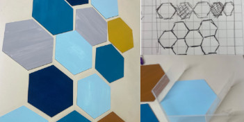 Hence, my idea
is to build the wall using hexagon forms, like simulating a bee panal. That kind of structure could
cover all or part of the wall. Could be built by modules, and each one could have different colors,
like legos that are sticked together. Thus, some hexagons could be blank and other could containg
funkos. In this way, not every hexagon serve as shelve, and coulb be build using playwood, and
replace some the hexagons with 3D printed colored pieces. Like some art wall that I found on a
friend house, that you can observe in the image. But instead of being 2D Hexagons stick in the wall,
I can produce 3D hexagons inserted in a playwood wall.
Looking for mechanisms that I can use
Thinking that I would need to use stepper motors and servo motors that I could use. I comented my idea during a global open time, thus I found some interest ideas, from artist and from previos FabAcademy Students. First I found Gonzalo Siu's FabAcademy 2015 final project.

During global open time I comment about my final prject idea and they suggest me to watch a group project develop by Benjamin Bente and Joany Jonathan from waag fab lab called the motion wall final project. .
Due to its similar functioning to a Cukoo Clock system, I look for someone that would replicate an automate Cukoo clock. I found Andy Bradford Web Page, that shares his project about a Connected Cuckoo Clock. Its result is show in the vieo below.
For my project I will need to design the following:
The following table provides details about the materials and components that I will use.
| Quantity | Unit | Description | Origin | Cost (USD) |
|---|---|---|---|---|
| 1 | Kg | One 3d printing filament | China | 26.32 |
| 6 | Pieces | 3mm mdf (0.30x0.60 mm) | Chile | 4.74 |
| 1 | Piece | 15mm mdf piece (0.60x 0.80 mm) | Chile | 6.58 |
| 1 | Piece | 3mm Color Acrylic (0.30x0.60 mm) | Chile | 4.74 |
| 1 | Und | XIAO ESP32C3 | China | 5.92 |
| 2 | Und | MG995 Servos Motors | China | 13.16 |
| 3 | Und | Micro limit switch 3P SPDT 1A 125V AC | China | 1.58 |
| 1 | Und | Nema 17 Stepper Motor | China | 13.16 |
| 1 | Und | XL4015 5A Voltage and Current regulator | China | 6.58 |
| 1 | Und | Energy source 12V | China | 13.16 |
| 4 | Und | One terminal block 2x1 | China | 0.53 |
| 8 | Und | One terminal block 3x1 | China | 1.05 |
| 3 | Und | One terminal block 4x1 | China | 0.53 |
| 3 | Und | Resistors 1k | China | 0.39 |
| 1 | Und | DRV8428E driver | China | 9.21 |
| 1 | Und | Trimmer 10K | China | 1.32 |
| 1 | Und | Unpolarized capacitor 0.1 uF | China | 0.26 |
| 1 | Und | Polarized capacitor 100 uF | China | 1.32 |
| 1 | Und | Unpolarized capacitor 1 uF | China | 0.26 |
| 1 | Und | USB Type-C Connector | China | 6.58 |
| 1 | Und | 10 Amps 125 Volts AC Power Cord Cable for Electronics | China | 2.63 |
| 1 | Und | MGN12H 350mm Linear Rail 11.6 | USA | 31.58 |
| 4 | Und | 1/2 inch Bore Bearing: R8-2RS bearing size: Inner Diameter: 0.5 inches (12.7 mm); Outer Diameter: 1.125 inches (28.575 mm); Width: 0.3125 inches (7.938 mm) | USA | 6.32 |
| 1 | Und | GT2 Timing Belt Pulley,16 Teeth 5mm Bore Aluminum Timing Belt Pulley Tool for CNC | USA | 2.11 |
| 40 | cm | GT2 Belt 2mm Pitch 6mm Wide | USA | 1.10 |
| 2 | Und | M5 Metric Hex Head Socket Cap Bolt | China | 0.05 |
| 2 | Und | M5 Metric Hex Nut | China | 0.05 |
| 4 | Und | M3 Metric Hex Head Socket Cap Bolt | China | 0.11 |
| 4 | Und | M3 Metric Hex Nut | China | 0.11 |
| 4 | Und | M3 Metric Screw | China | 0.11 |
| 4 | Und | M3 Metric Nut | China | 0.11 |
| 4 | Und | M3 Self Drilling Screws for wood | China | 1.05 |
| 2 | Und | M8 Self Drilling Screws for wood | China | 1.05 |
| - | - | Dupont cables M-F | China | 0.66 |
| - | - | Dupont cables M-M | China | 0.66 |
For my project I will made/fabricate the following:
For my project I will use the following processes:
At this moment, the following questions arise:
Could a program be created to move both servo motors simultaniously in opposite directions at the
same time?
Could the integration be achieved without delays?
Should other materials be used to fabricate the case?
Would be useful to replicate a 3D printer mechanical movement of the platform?
I will answer those question while designing and fabricating my prototype parts in the following
weeks, while trying to stick to the project plan that you can see in the following pictures


The main function of the machine is to create showcase and hide objects (funkos), so the project will be evaluated based on achieving both objectives. For testing purposes, I will used real toys expenting to recreate a stable XY axis movement. Additionally, each system must be tested separately: The servo motors need to be able to open the printed top, and it would be tested first. Then I will test the limit switches systems, the fisrt one located at the base of the mobile top that will active the stepper motor to generate the platform movement. Then, the second switch will alert the motor to stop the showcase. Then, a new command will activate the platform movement in opposite way and the third switch will stop the motor again, complete hidden the object.
Estimated costs taken from Sai SAC Store