WEEK 4
Electronics production
Assignment:
Group Assignment:
- Characterize the design rules for your in-house PCB production process
- Send a PCB out to a board house
Individual Assignment:
- Make and test a microcontroller development board
- Extra credit: personalize the board
- extra credit: make it with another process
This week, I learned about the different techniques for making electronic boards, the materials and tools used. I also learned to use a machine to make my own board and i made some tests, learned to solder, and to test the board I made.
Group Assignment
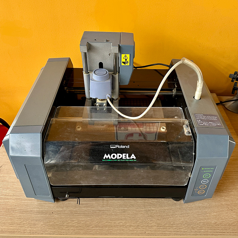
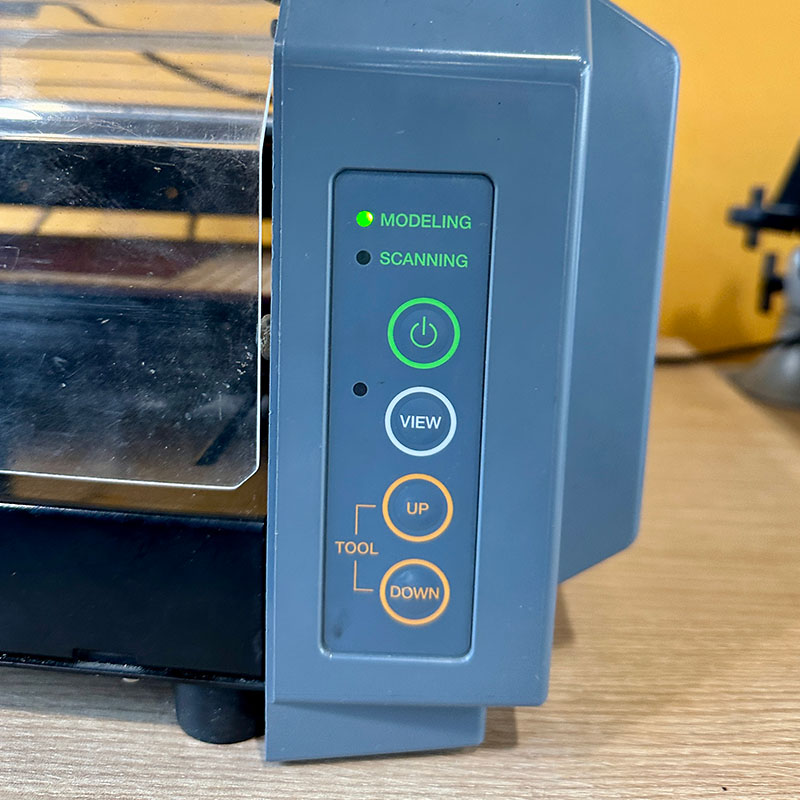
In the Esan fab lab, we have this machine the Modela MDX-20 from the Roland brand. It's quite easy to use since the software does almost all the setup work. It has 4 buttons on its front panel that allow you to turn it off, move it, and calibrate the tool's height. Even though all the machining is automatic, the calibration on the z-axis is manual, so you have to lower the tool gradually to avoid breaking it.
Some features of the milling machine are as follows:
- Max. operation area: 203.2 mm (X) x 152.4 mm (Y) x 60.5 mm (Z)
- Max. table load weight: 1000 g (2.2 lb.)
- Interface: Serial (RS-232C)
- Acceptable material: Wood, Plaster, Resin (modeling wax, styrenform), Chemical wood, Aluminum (A5052 according to JIS), Brass
- Tool chuck: 6 mm or 1/8 in. tool chuck included
- Revolution speed: 6500 rpm
- Feed rate: 0.1 to 15 mm/sec.
- External dimensions: 476.8 mm (W) x 381.6 mm (D) x 305 mm (H)
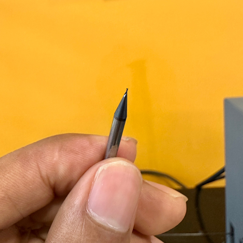
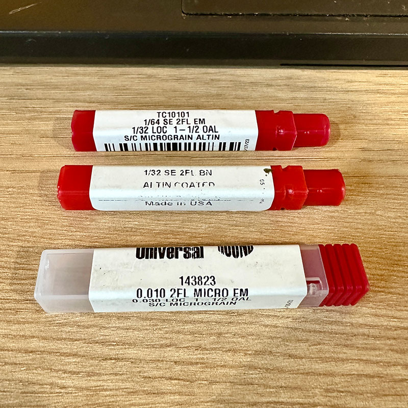
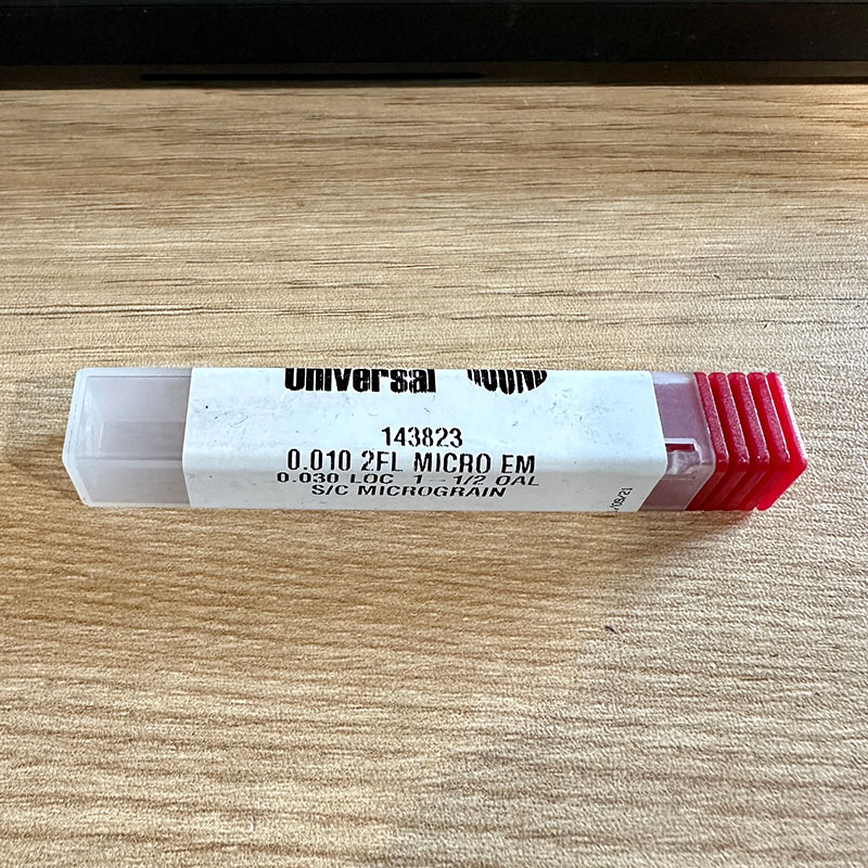
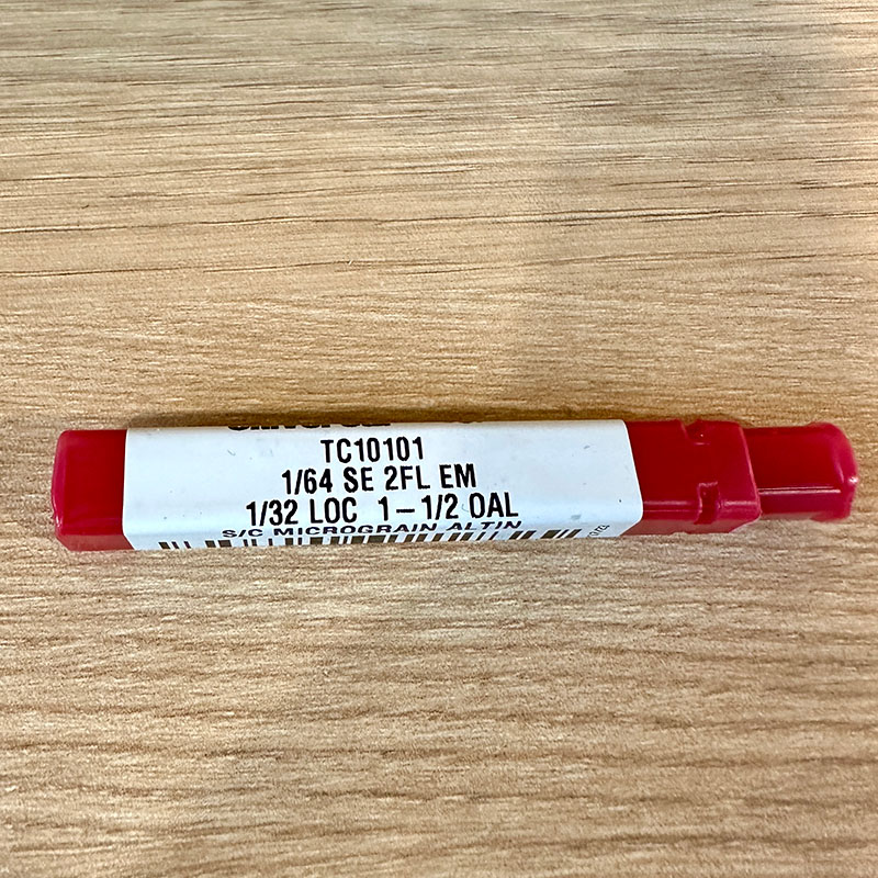
Since the tracks of the borads are quite small, very small mills are used for machining. On this occasion, I mainly used three: a 1/64” mill for milling the traces, a 1/32” one typically for making the cuts, and a 0.001” one when the traces are smaller. It's important to be careful because if one of these mills falls, it's very likely to break.
This week, we learned about making PCBs, but we haven't learned to design them yet. For that reason, we used the files of the board that was shared in the class. To calculate the tool paths, we used a web application called Mods Project. This application allows you to connect to the milling machine and send the cutting files. Although it is a web application, at the Esan Fab Lab, we have it installed locally. Once you load the profile of the milling machine, it's quite easy to use.
It's possible to use a PNG or SVG file; in this case, I used the PCB design in PNG format.
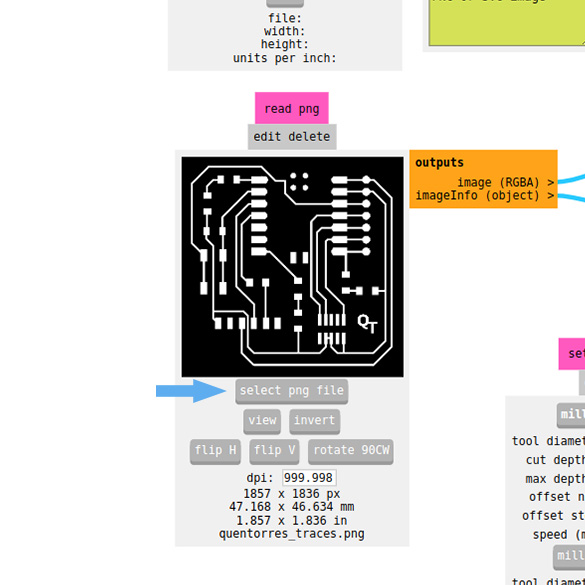
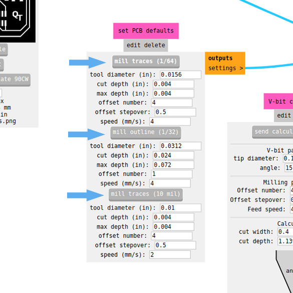
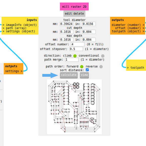
The next step is to select the mill that will be used, depending on the task to be performed on the milling machine, whether it's cutting or milling, and then calculate the toolpath.
The next panel allows us to select the origin of the machining coordinates. This is very useful when making multiple borads on a single FR1 plate. Since we have Mod installed locally, I used the websocket panel with pyserial instead of web serial. To make this switch, I simply had to deactivate and activate the indicated switches. Then, on the websocket panel, I opened the port to establish communication with the machine.
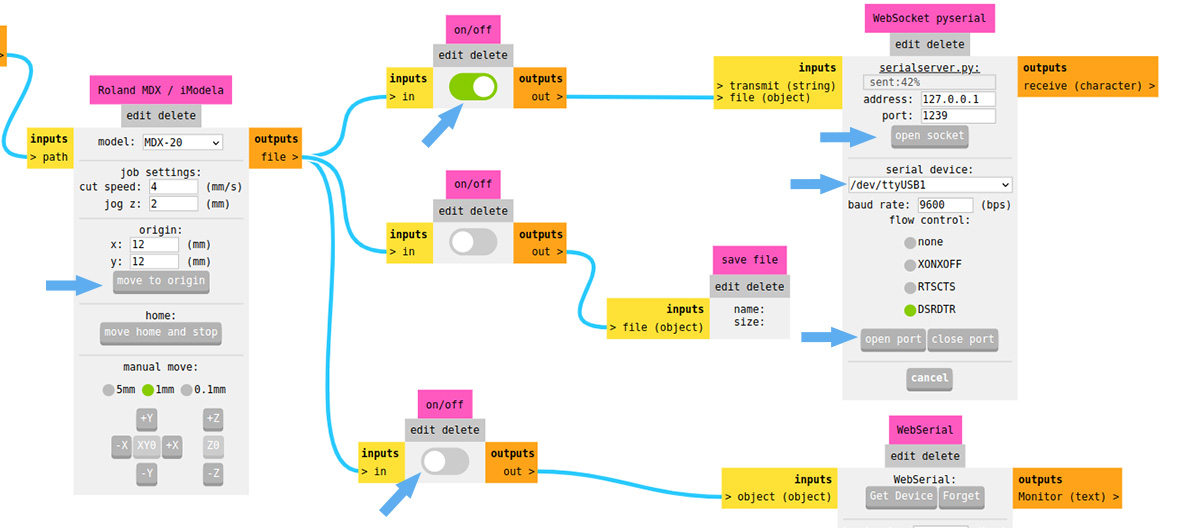
Having the machine configured, the only thing left is to calibrate the zero on the z-axis. This calibration must be done manually and each time the mill is changed. To perform the calibration, simply lower the tool using the buttons on the machine's front panel. When it's about 3 mm away, lower it with extra care. When it's noticed that it has removed a bit of material, that's when you need to stop.
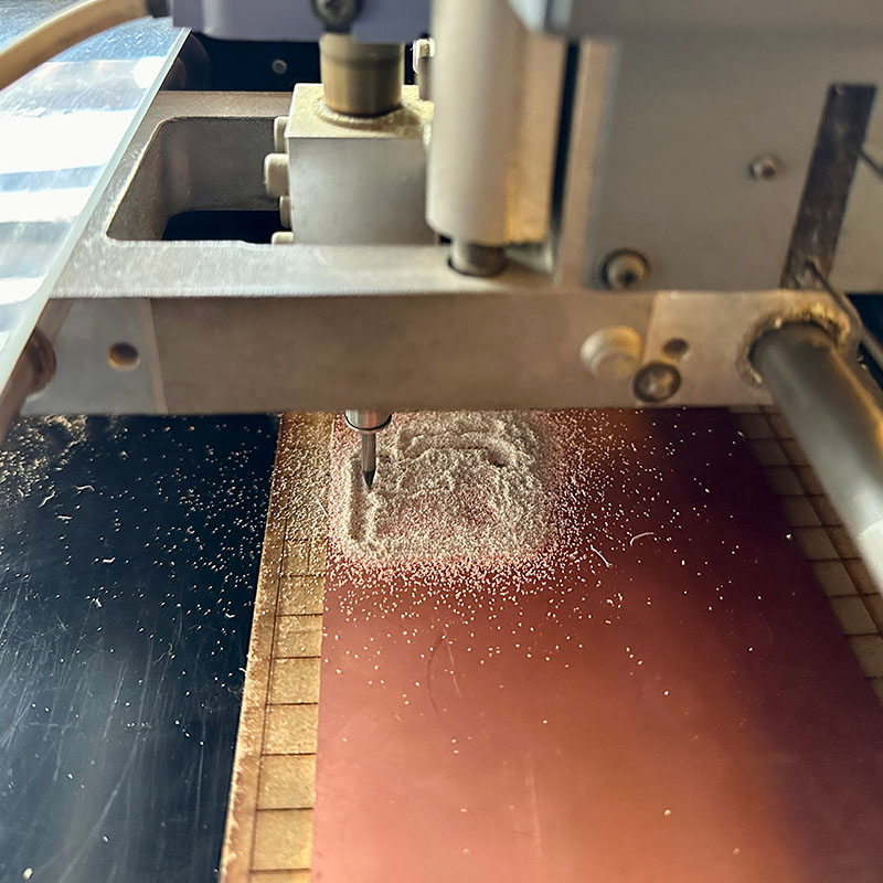
Once the zero is calibrated, you can start machining. For the tests, I used the 0.001” and the 1/64” mills.
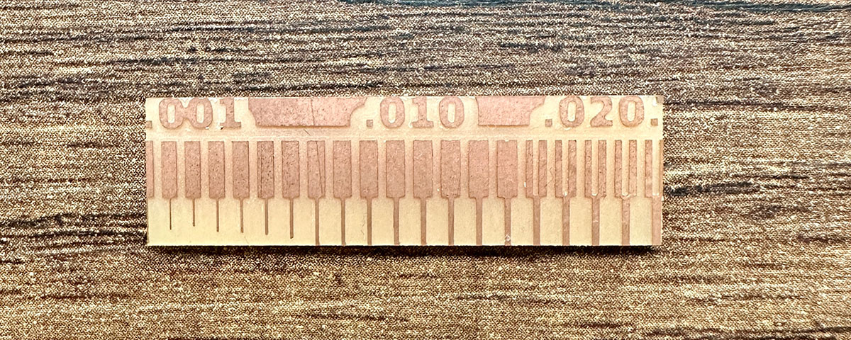
The image I used for the test is as follows: it has lines of different separations and thicknesses.

The following image shows the result of milling with the 0.001” mill.
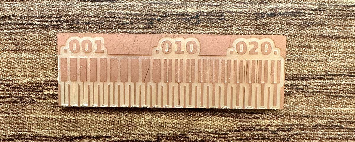
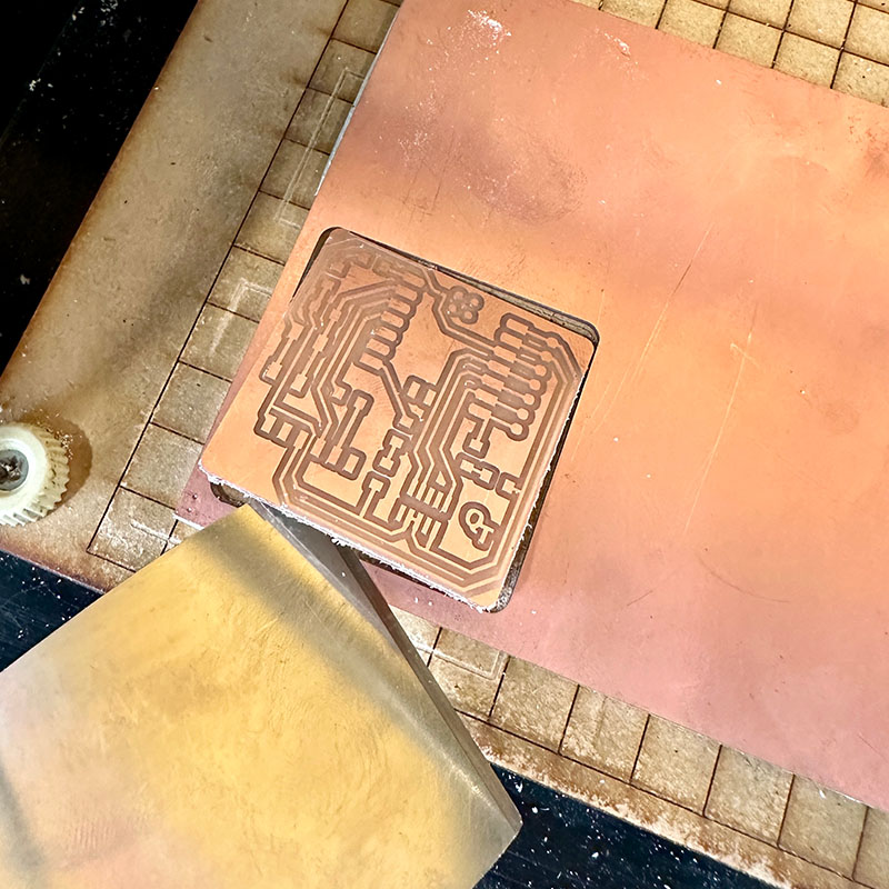
The following image shows the result of milling with the 1/64” mill.
Individual Assignment:
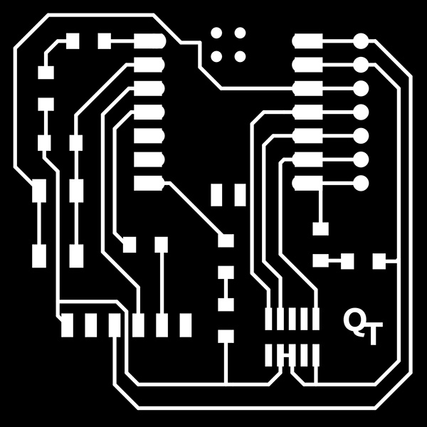
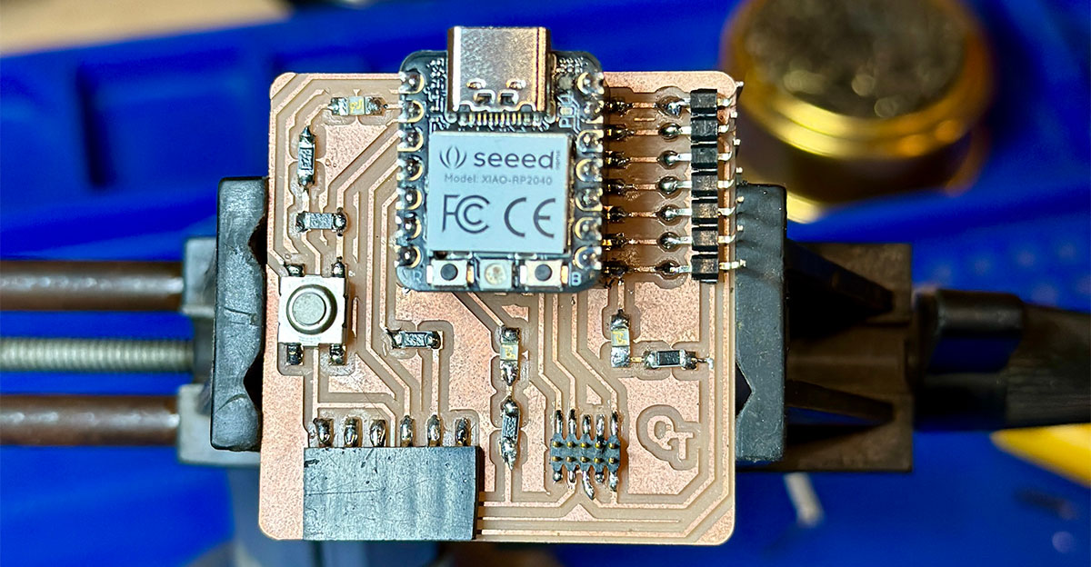
In this part, I made one of the development boards for the XIAO-RP2040 microcontroller developed by Quentorres. I obtained the files from their website.
I used the images of the boards in PNG as in the previous test and Mods to generate the toolpath. After securing the FR1 board with double-sided tape on the machine, I proceeded with the zero calibration on the z-axis. I did this first with the 1/64” mill to remove the copper and then with the 1/32” mill to make the cut.
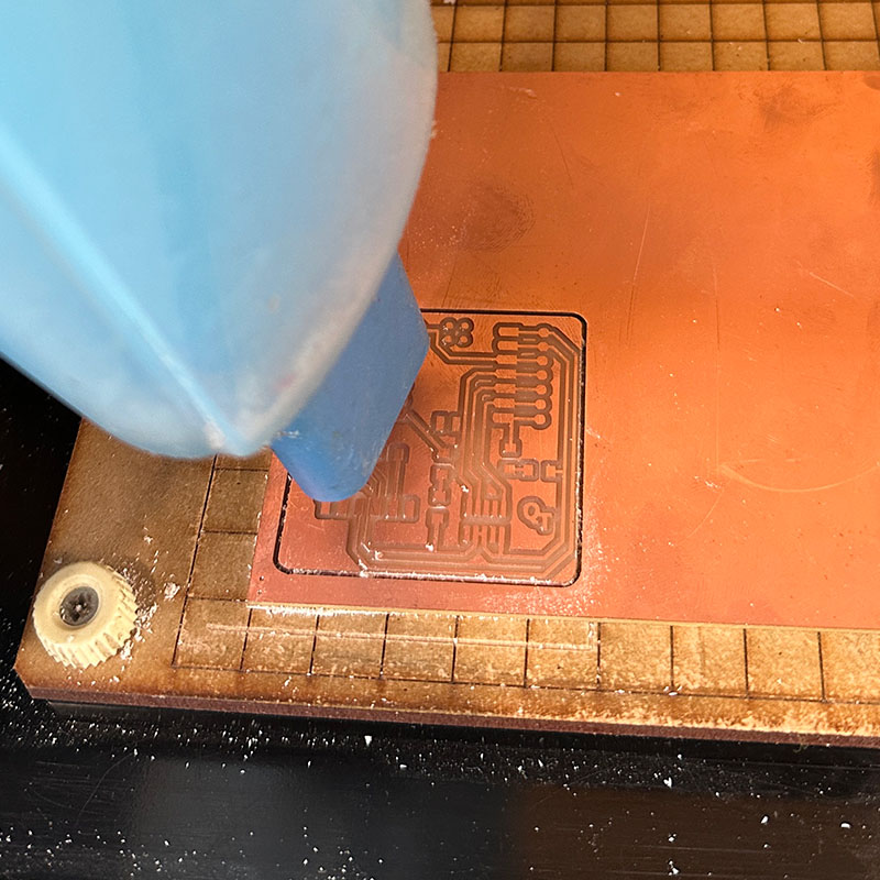
Once the cutting was finished, I removed the board from the machine, cleaned it, and proceeded to solder each component. But before that, I did some soldering tests to better learn the technique.
The necessary components are as follows:
| Item | Components | Amount |
|---|---|---|
| 1 | SEEED STUDIO XIAO RP2040 | 1 |
| 2 | CONN HEADER SMD 10POS 1.27MM | 1 |
| 3 | CONN HEADER SMD R/A 6POS 2.54MM | 1 |
| 4 | Tactile Switch SPST-NO Top Actuated Surface Mount | 1 |
| 5 | LED BLUE CLEAR 1206 SMD | 3 |
| 6 | RES 1K OHM 1% 1/4W 1206 | 4 |
| 7 | RES 499 OHM 1% 1/4W 1206 | 1 |
| 8 | CONN HDR 7POS 0.1 TIN SMD | 2 |
I think the soldering result is quite acceptable. The most difficult parts to solder were the resistors and LEDs because they are very small components. I also had to bend the legs of some components to better fit them onto the board. The final result can be seen in the following image.
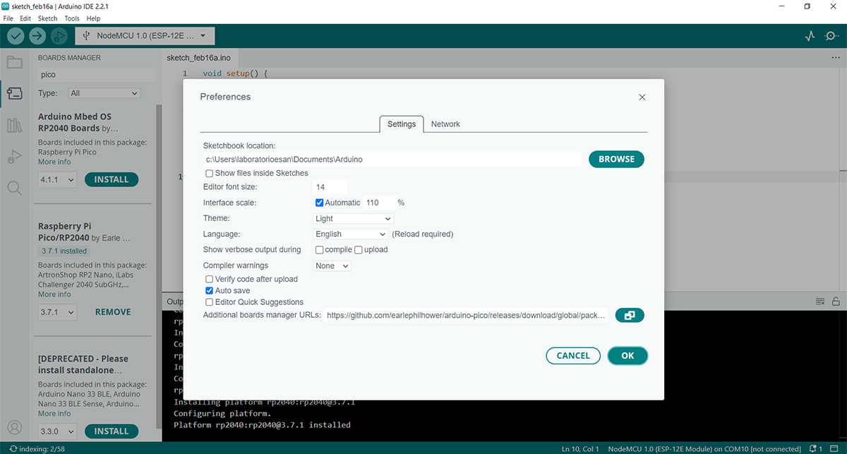
After finishing soldering the components, I wrote a small program in Arduino to test the board. It's a quite simple program to turn one of the LEDs on and off. But first, I had to add the board from the program's preferences as shown in the following image. For this part, I used the work of earlephilhower.
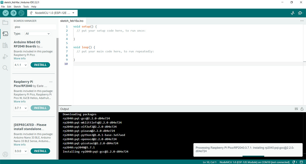
Then, you need to install the Raspberry Pi Pico/RP2040 from the board manager of the IDE.
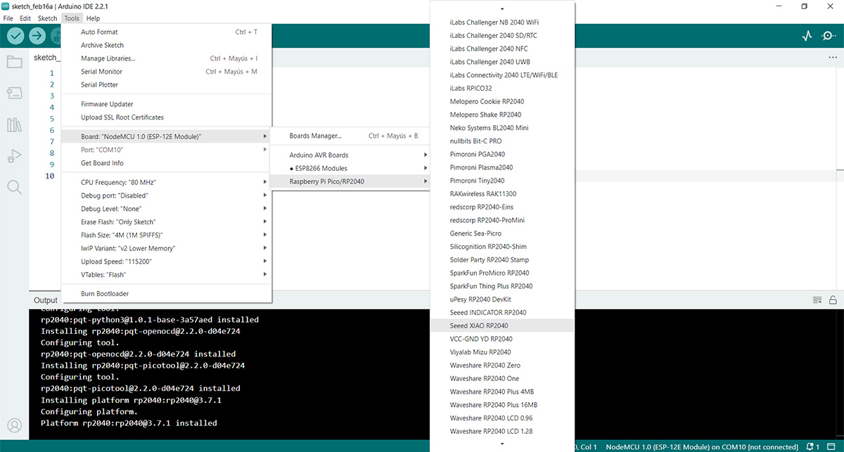
Finally, select the board from Tools. With this setup, you can start programming.
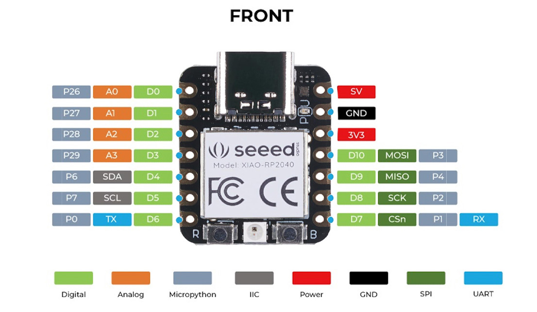
To test, I uploaded this program to the board. It's simply to turn the LED connected to pin 26 on and off in the Quentorres board. In the iamge we can see the locacion of the 26 pin in the xiao
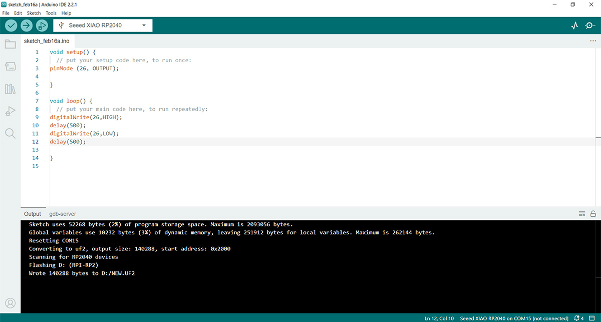
//blink a led program
void setup() {
pinMode (26, OUTPUT);
}
void loop() {
digitalWrite(26,HIGH);
delay(500);
digitalWrite(26,LOW);
delay(500);
}
Finally, we upload the program to the board.
This is the result of the test. I had to change the LED connected to pin 1 because it wasn't working, probably due to overheating it while soldering.