Assignment
Group Assignment:
- - Design a machine that includes mechanism, actuation, automation, application - Build the mechanical parts and operate it manually - Document the group project and your individual contribution.
Research
Group Assignment Continued
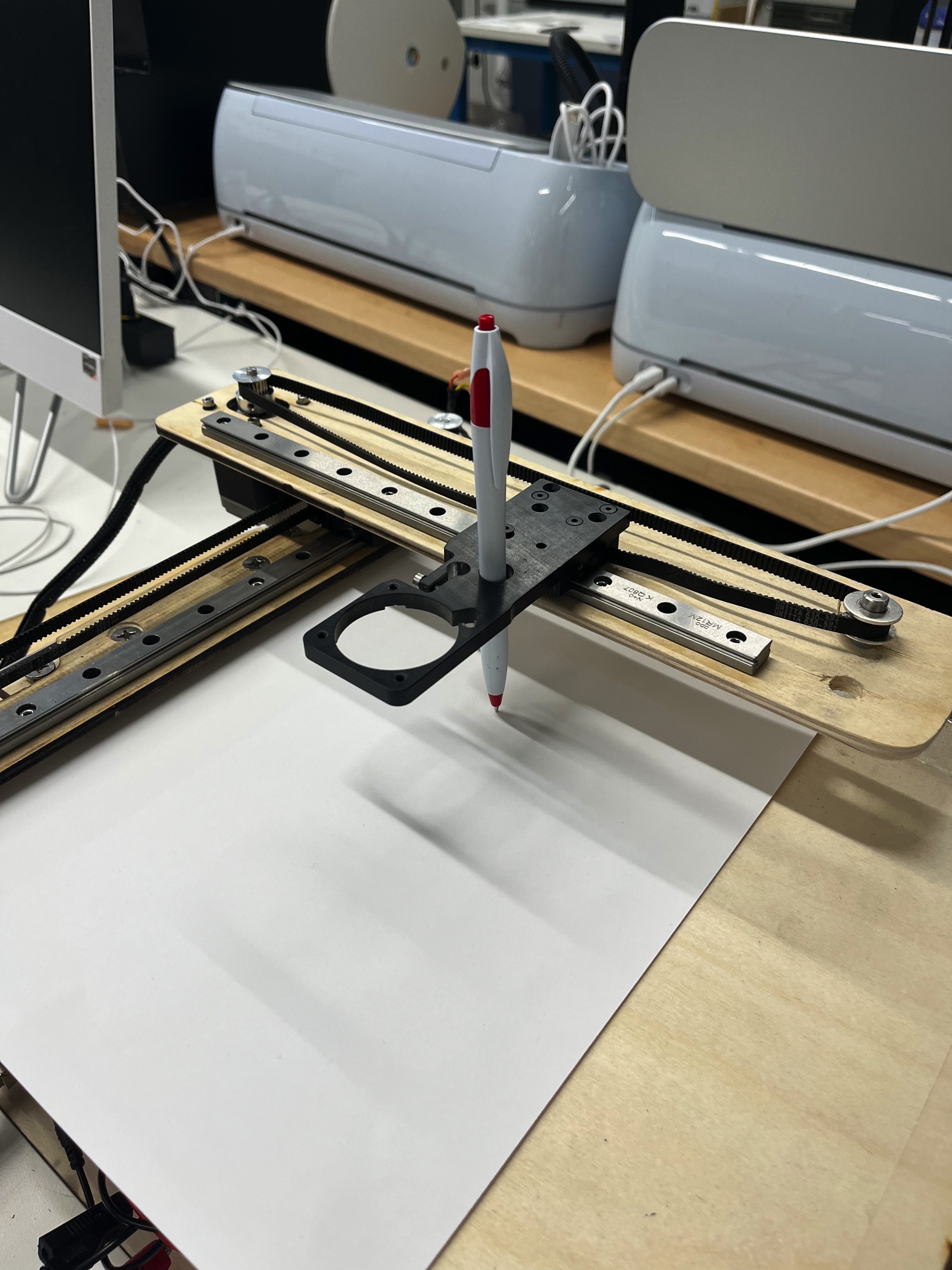
- We started by brainstorming how we wanted to address the assignmet and we ultimately decided to build a CNC Pen Plotter from parts taken from an old MakerGear 3D printer.
- First, we disassembled the old printer to see what parts we had AND to see which parts we in working order.
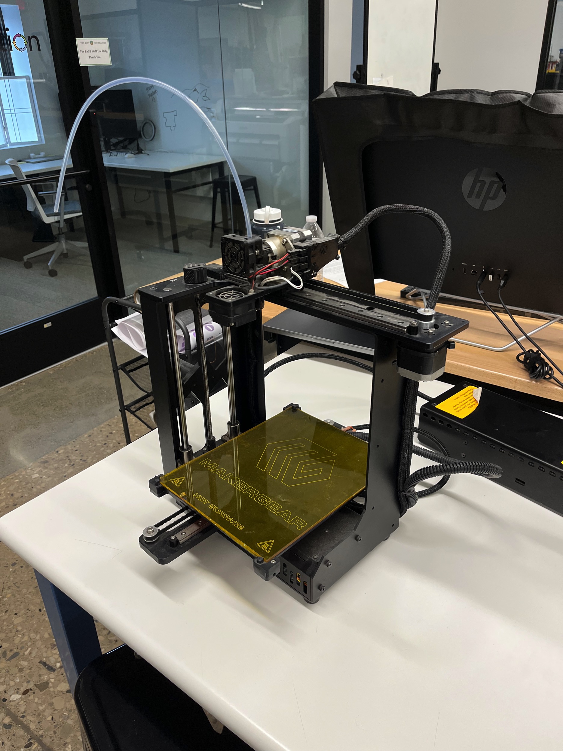
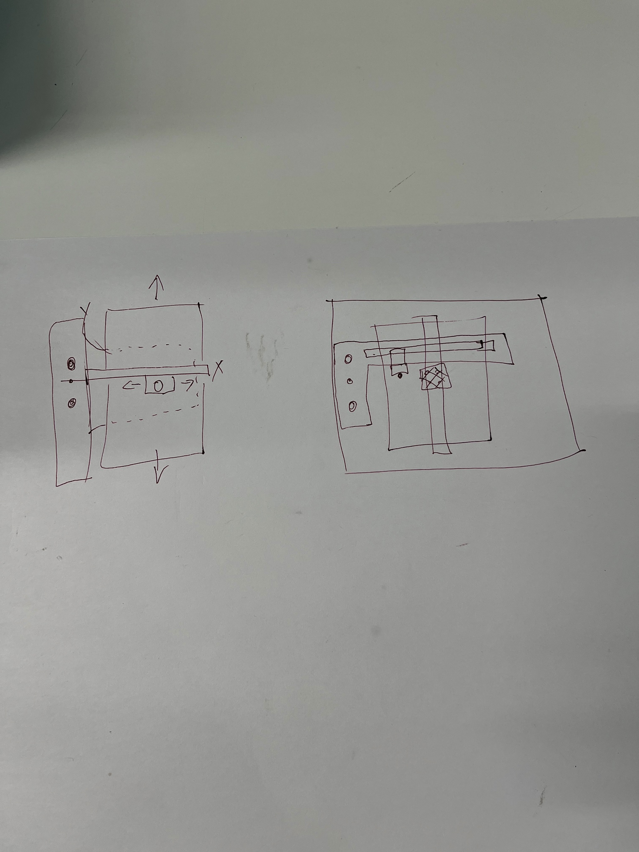
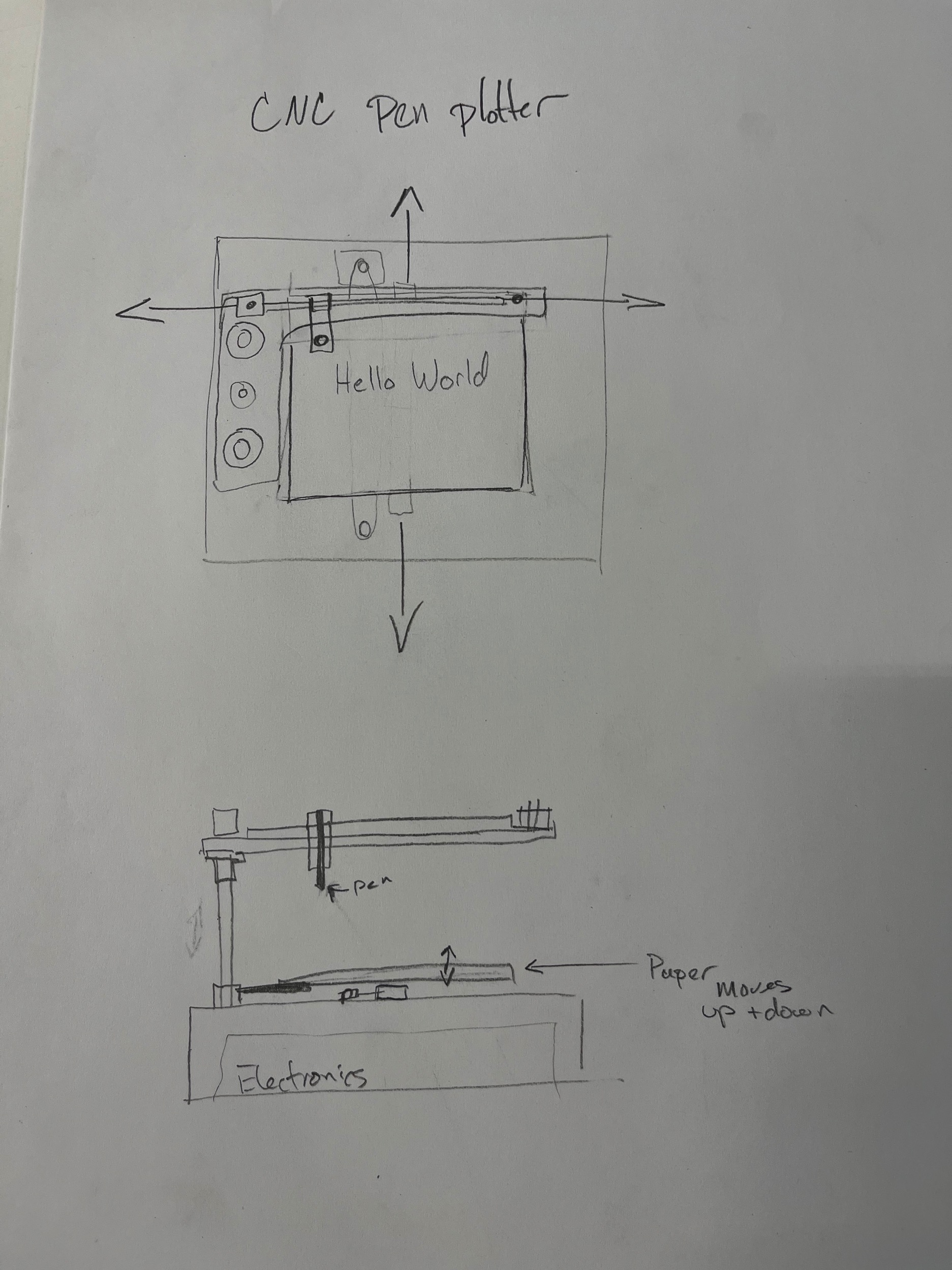
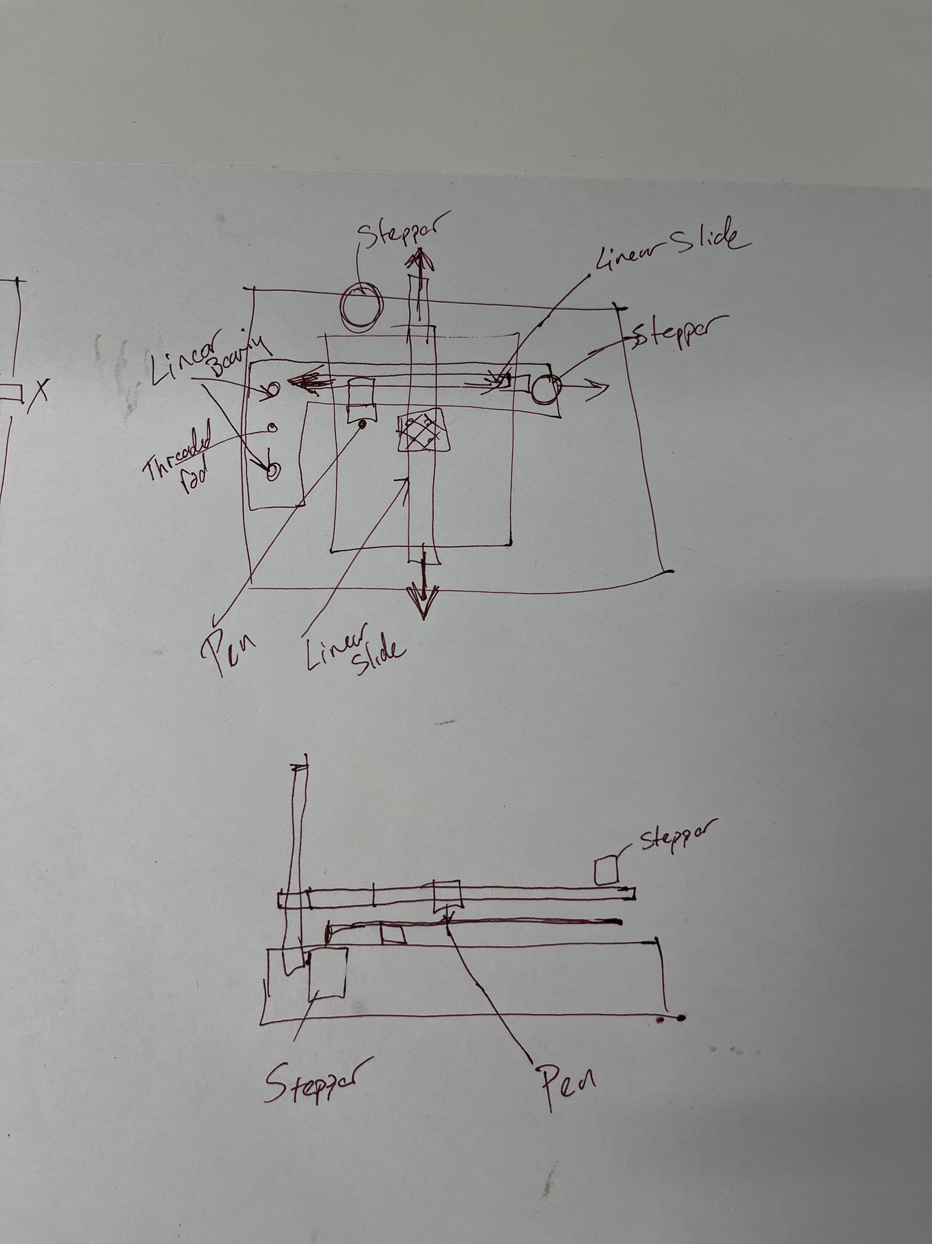
- Next, we sketched out our concept based on the parts we had and the parts we would need to design to make the plotter work.
- Next, we created a CAD model of our original idea. The CAD model helped us get a better visual of the machine and allowed us to more rapidly modify the designs for laser cutting.
- Once the parts were cut we were able to assemble the mechanical components of the pen plotter.
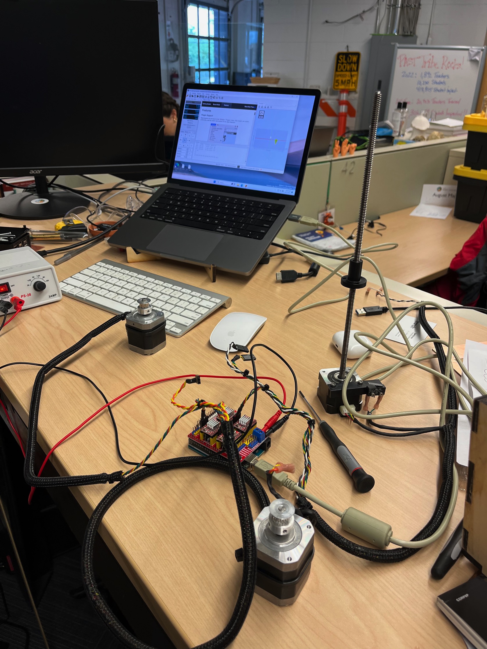
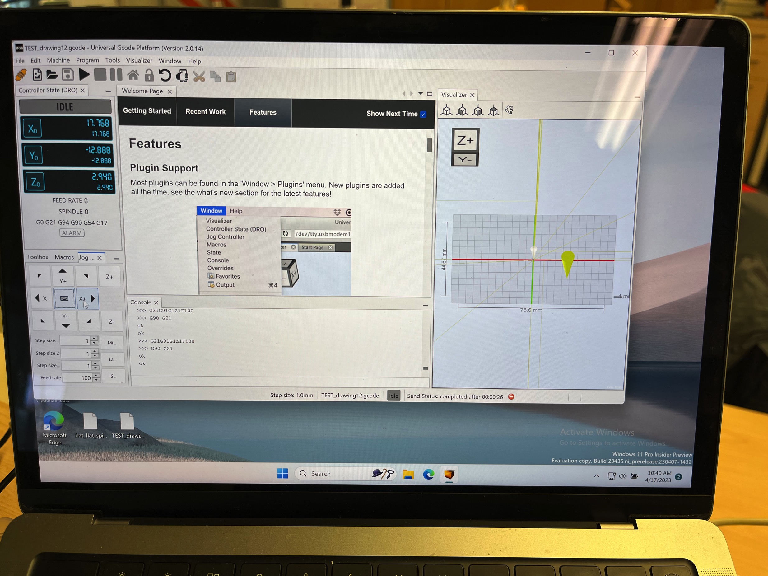
- While the mechanical components were being cut and assembled, we started the programming on an Arduino Uno. The first step was to add the GRBL library to be able to control the stepper motors. Next, we installed Universal Gcode Sender (UGS) on our laptop.
- We did run into several issues along the way. We use Mac computers with M1 processors and ran into issues with the installation. Ultimately, we used Parallels to run Widows on the Mac and everything started working much better.
Future Development of Poly the Plotter
The images below and the video is on our Group Assignment link above.
Design Files
Screw Pad File X & Y Axis Part File Box Base File Arduino GRBLuploadIndividual Contribution
My contribution to this week's assignment consisted of the following:
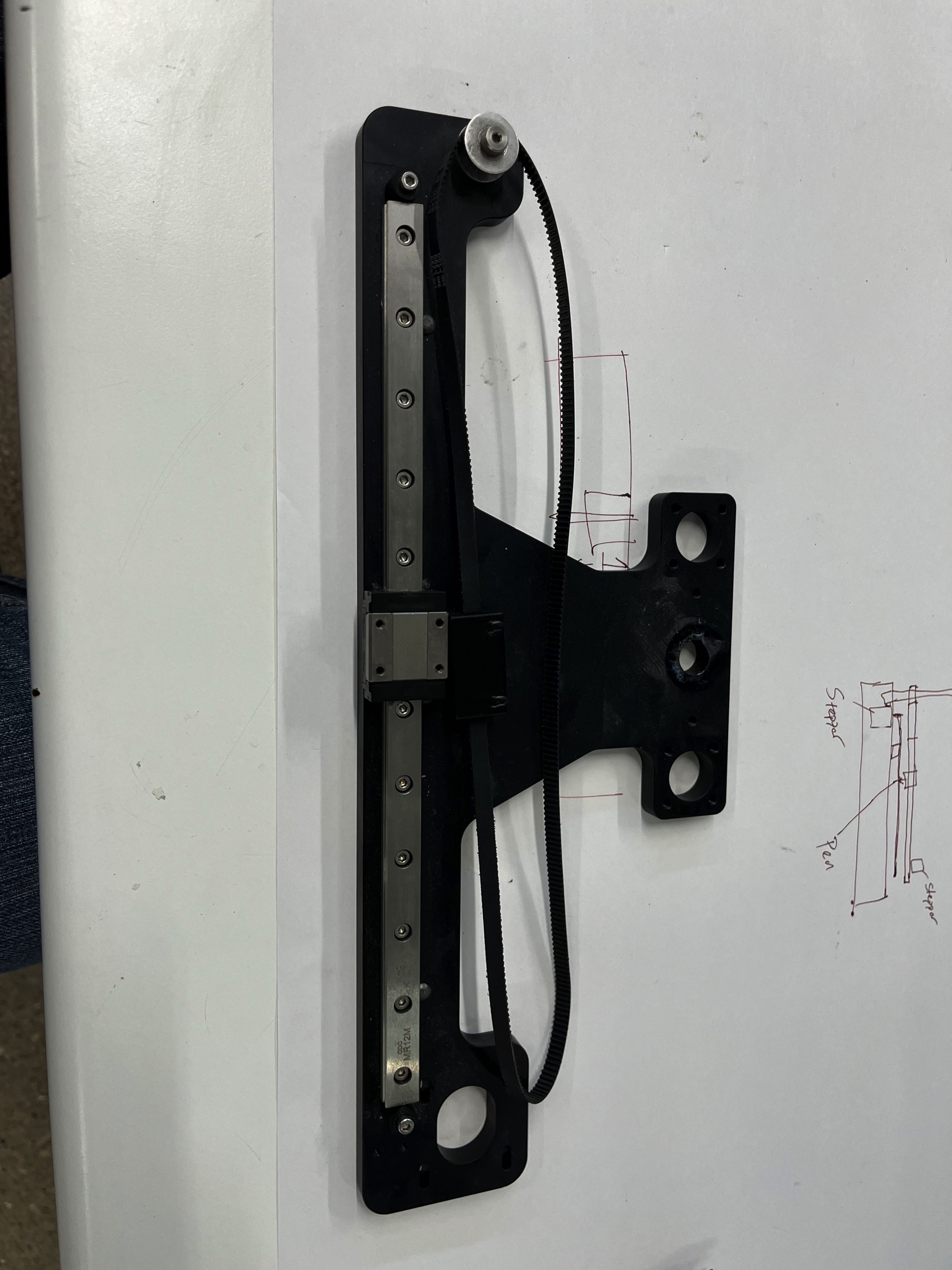
- I disassembled the MakerGear 3D printer to determine what parts we had to work with and what parts we would have to fabricate to make our pen plotter a functional machine. I wanted to take the stepper motors, belts, and linear slides from the 3D printer since I knew they already worked. These parts would also help determine the overall size of the plotter we would make.
- Then I began to research how to make all the individual parts work together. I watched several YouTube videos (see Research section above) to learn about Universal Gcode Sender and the Arduino CNC motor shield.
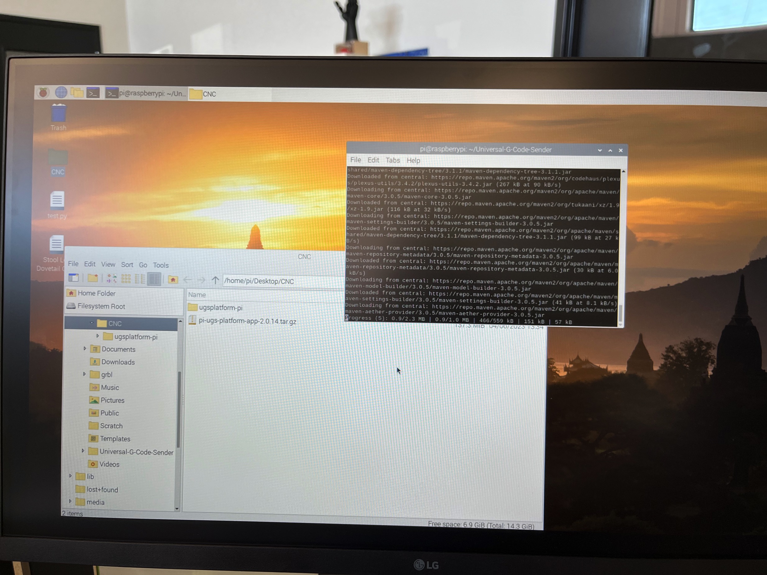
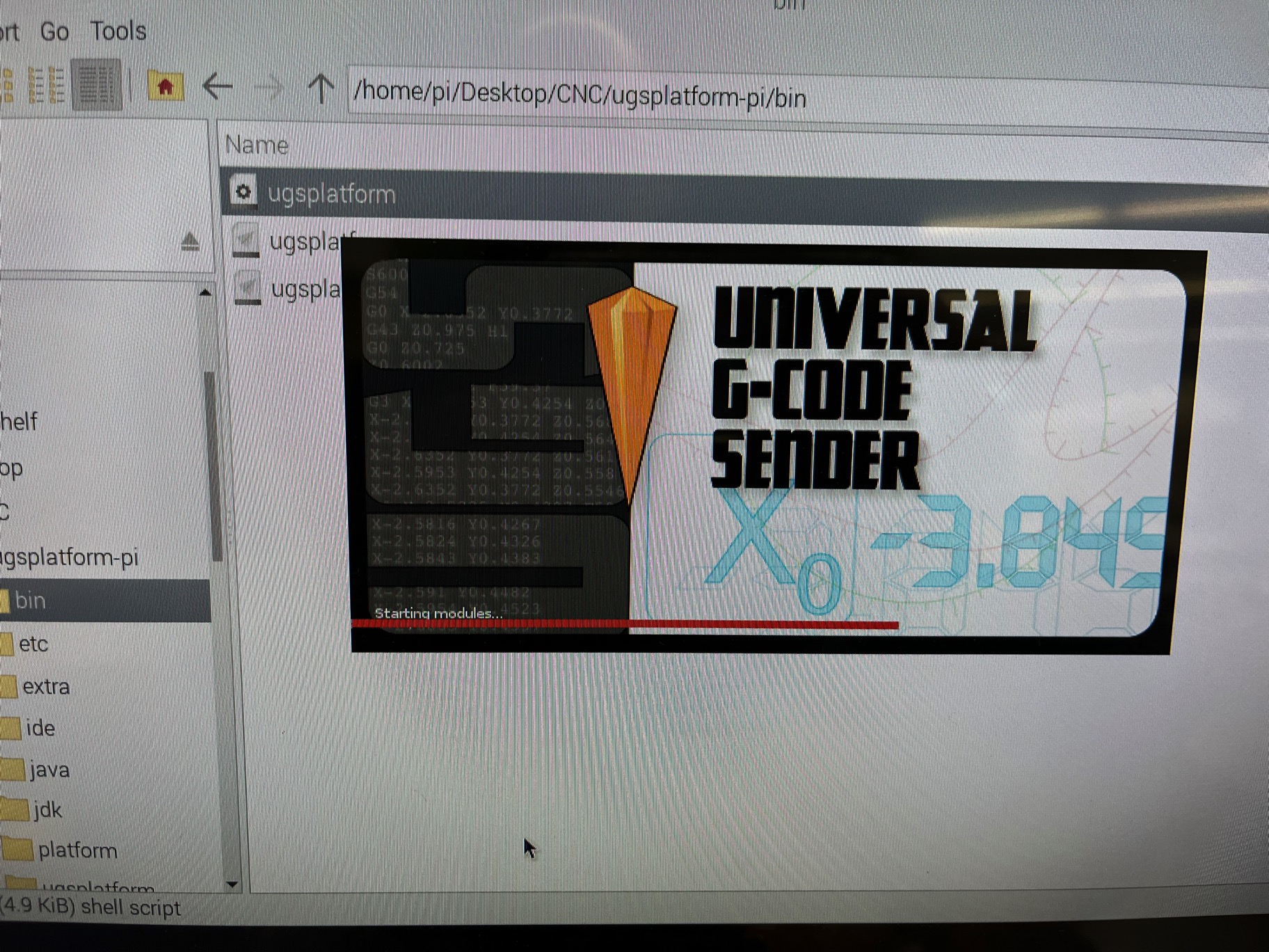
- After figuring out WHAT I needed to do I then needed to find out HOW to make it all happen. This was the hardest part. I tried to run everthing off a RasPi but but I struggled to get that to work so I ended up doing it from my MacBook. Some of the issues were related to connecting the UGS to RasPi...I could install and open the application but nothing would actually work.
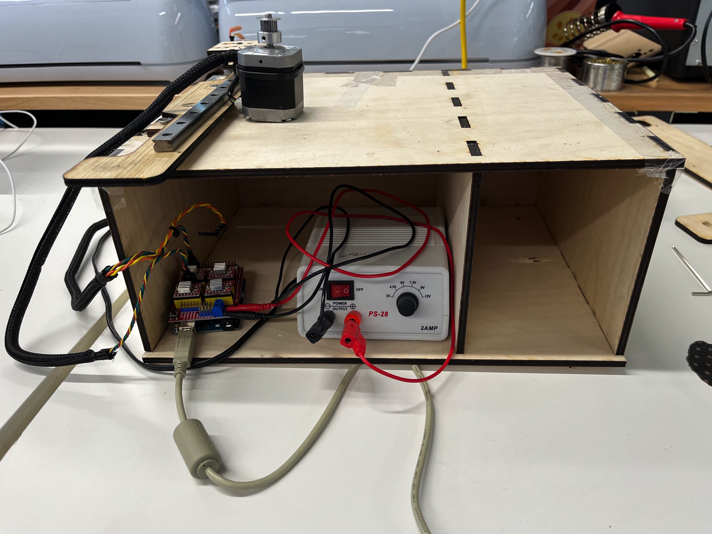
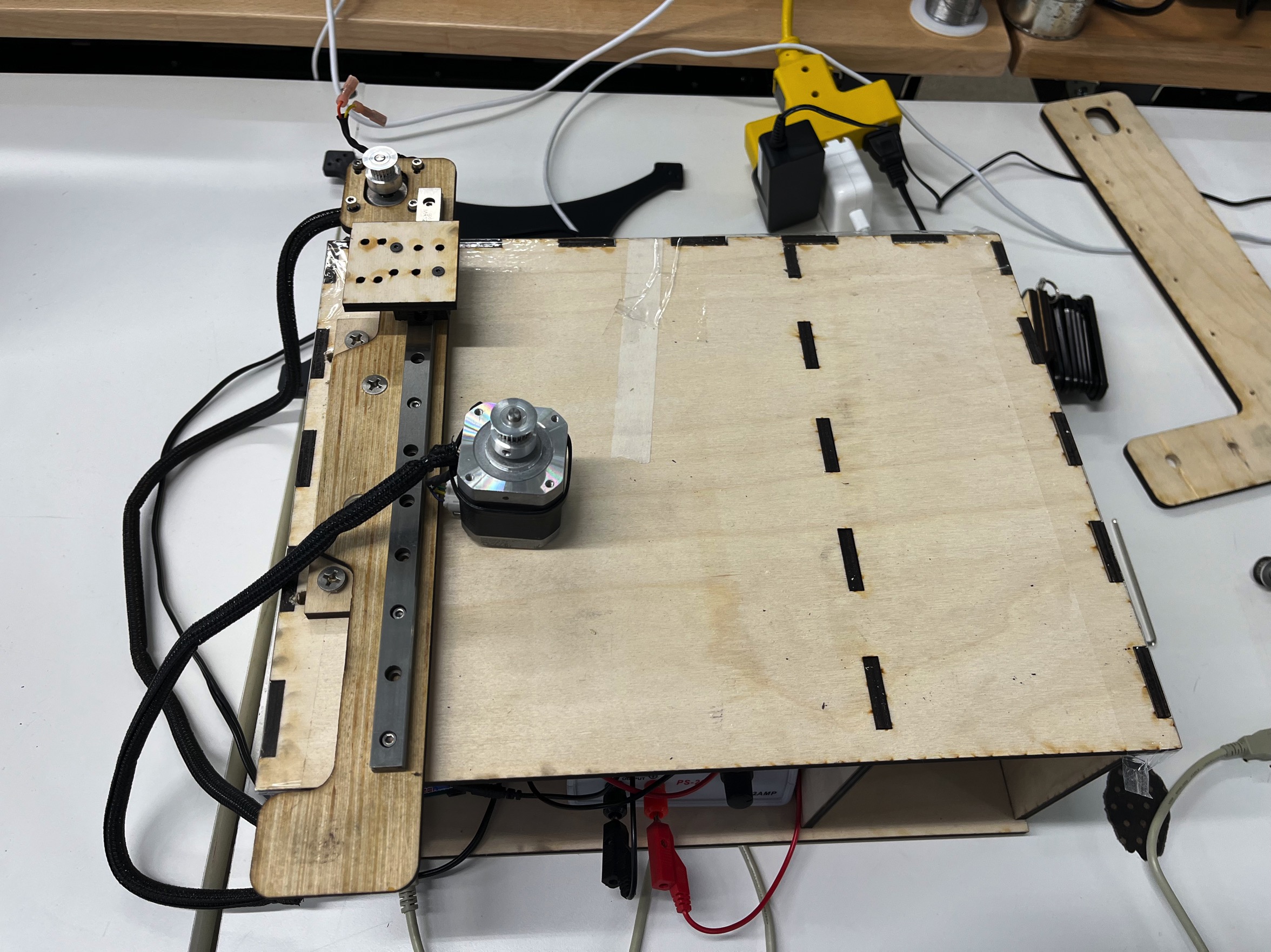
- After my partners fabricated the additional parts needed (box or body for the plotter, rail mounting components, and other small laser cut parts) I dry fit the motors, pulleys and belts, and linear slides together to make sure they all worked together again. Once I was happy with the the fit I began to asseble the final plotter.
- Next was wiring the motors and testing the beltdrive system. The pictues illustrate the process. The parts worked well for the most part. Iteration 2 will require adjustments to the spacing to the belts are tighter and there is no slop in the motion of the mechanism>
- After everthing was assembled and programmed I used the Biteable application to edit and create the documemtaion video for class.