Assignment
Individual Assignment:
- Design a development board to interact and communicate with an embedded microcontroller
- Extra credit: Try another design workflow
- Extra credit: Make a case for it
- Extra credit: Simulate its operation
Group Assignment:
- Use the test equipment in your lab to observe the operation of a microcontroller circuit board.
posted on Kelleigh's page since we do not have a group work page. We all worked together on this even though it is on Kelleigh's page
Research
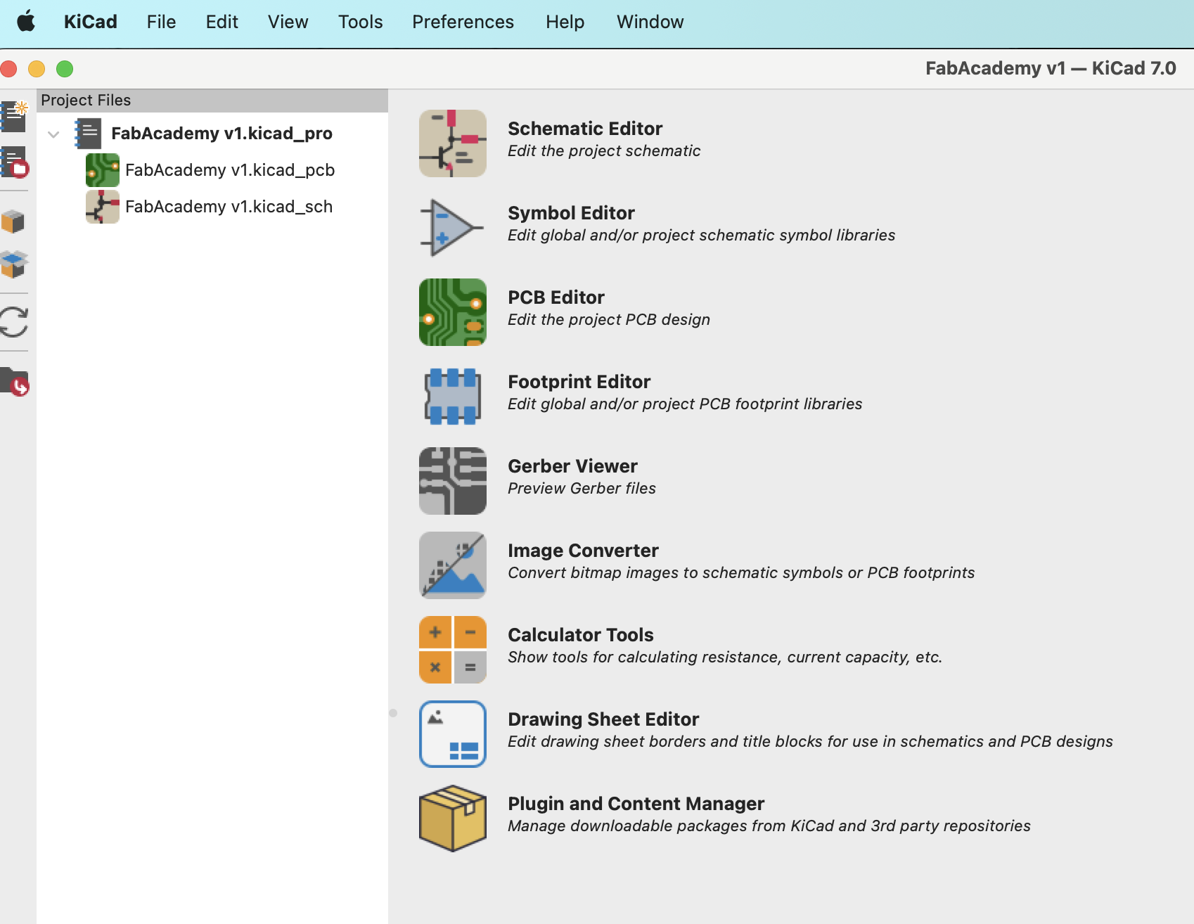
- I started by downloading and installing KiCad.
- After installing KiCad, I watched a few tutorials to better understand how to use KiCad.
- I followed the tutorial to create the stop light board even though it was the wrong format. The tutorial showed a through hole example rather than surface mount but it did give me a giid idea of how to use the applicaiton so I could create my own circuit using the proper components.
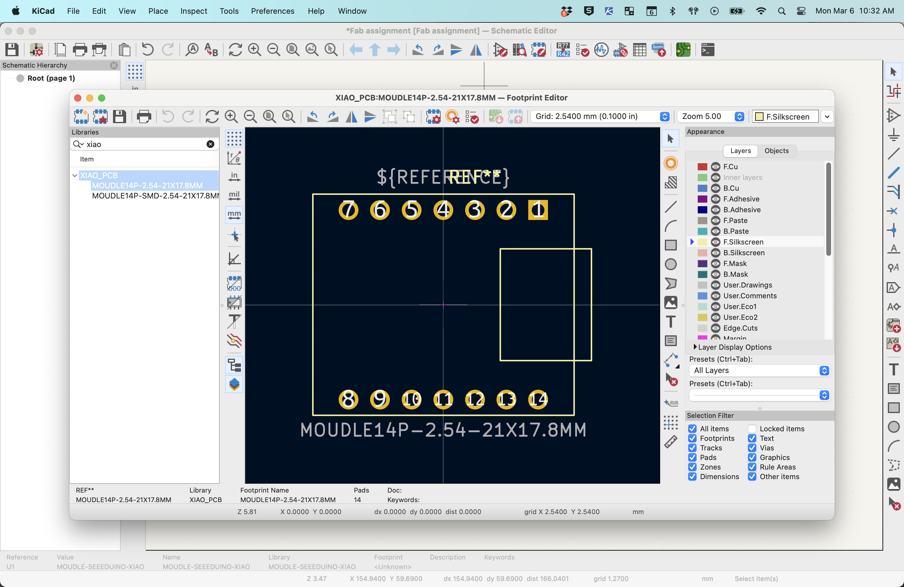
- After completing the tutorial design, I had to upload the Fab Library for KiCad so that I could use the proper components in te schematic as well as the footprints for the surfave mount of the Seeed Studio Xiao RP2040. This was a little tricker than it should have been since I was not able to download the correct files at first. Once I found the correct files and installed the footpriint library I was able to create a simple LED circuit fairly easily.
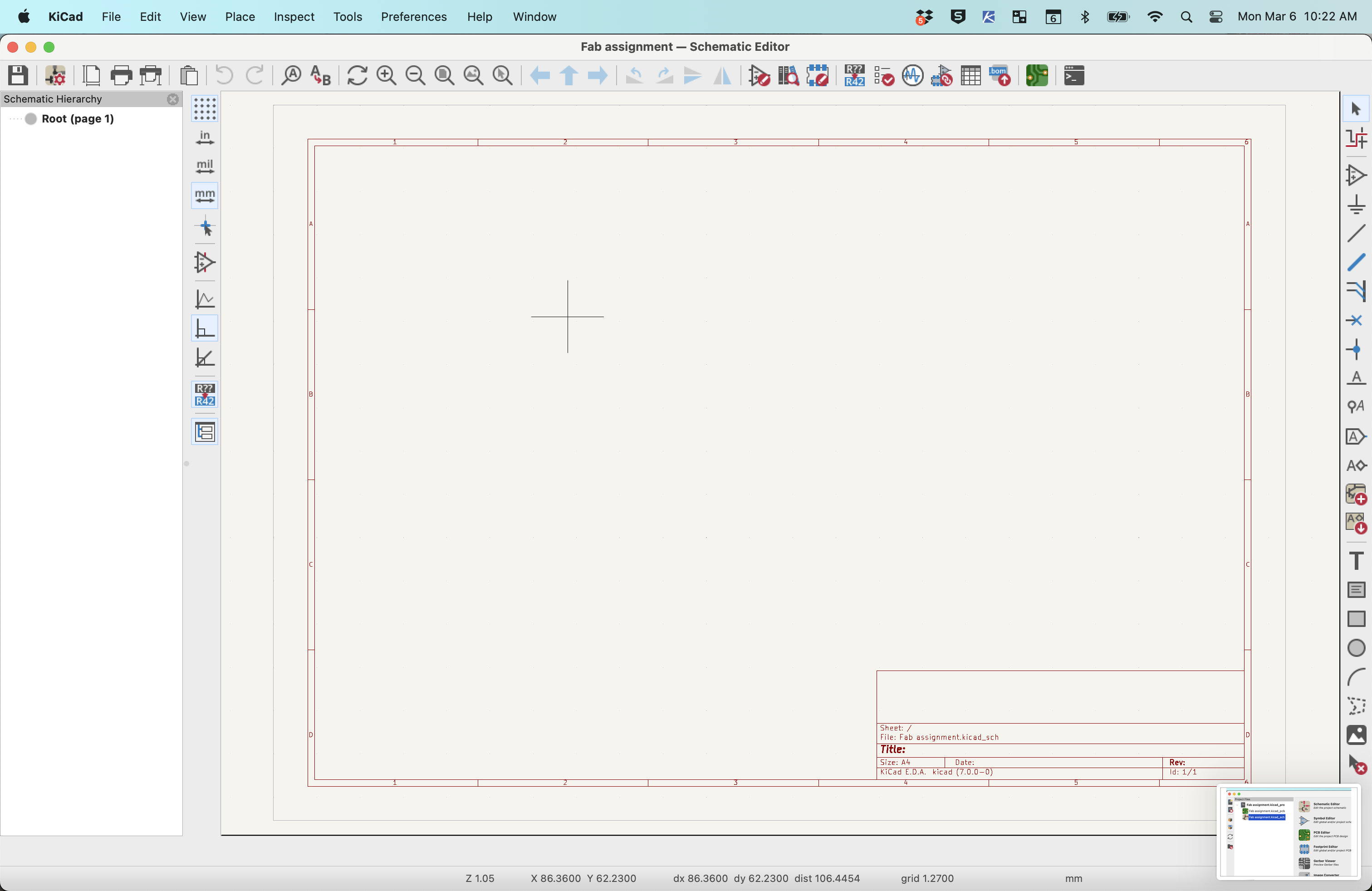
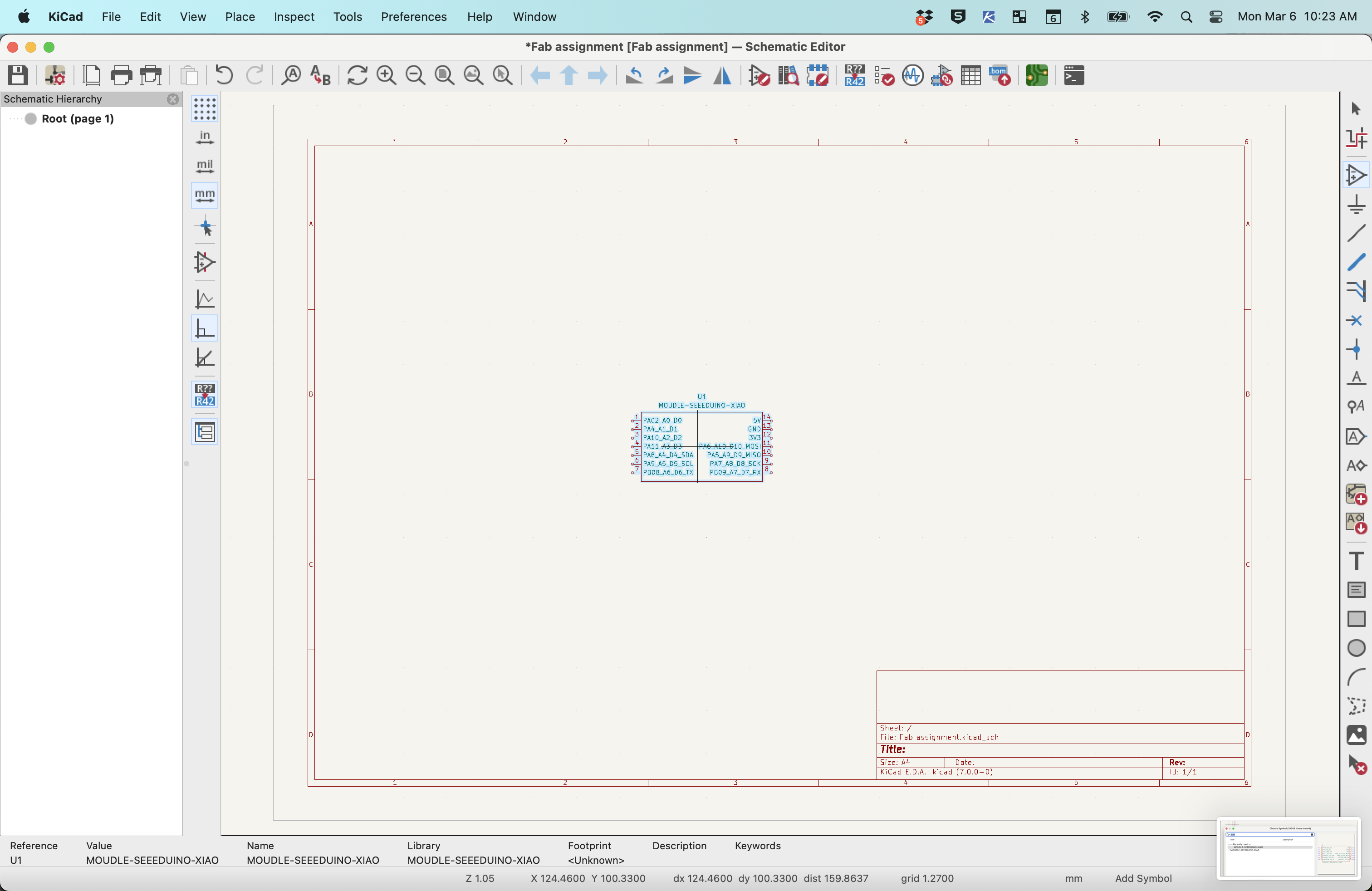
- For the correct PCB, I created a new project and began similarly to the stop light project.
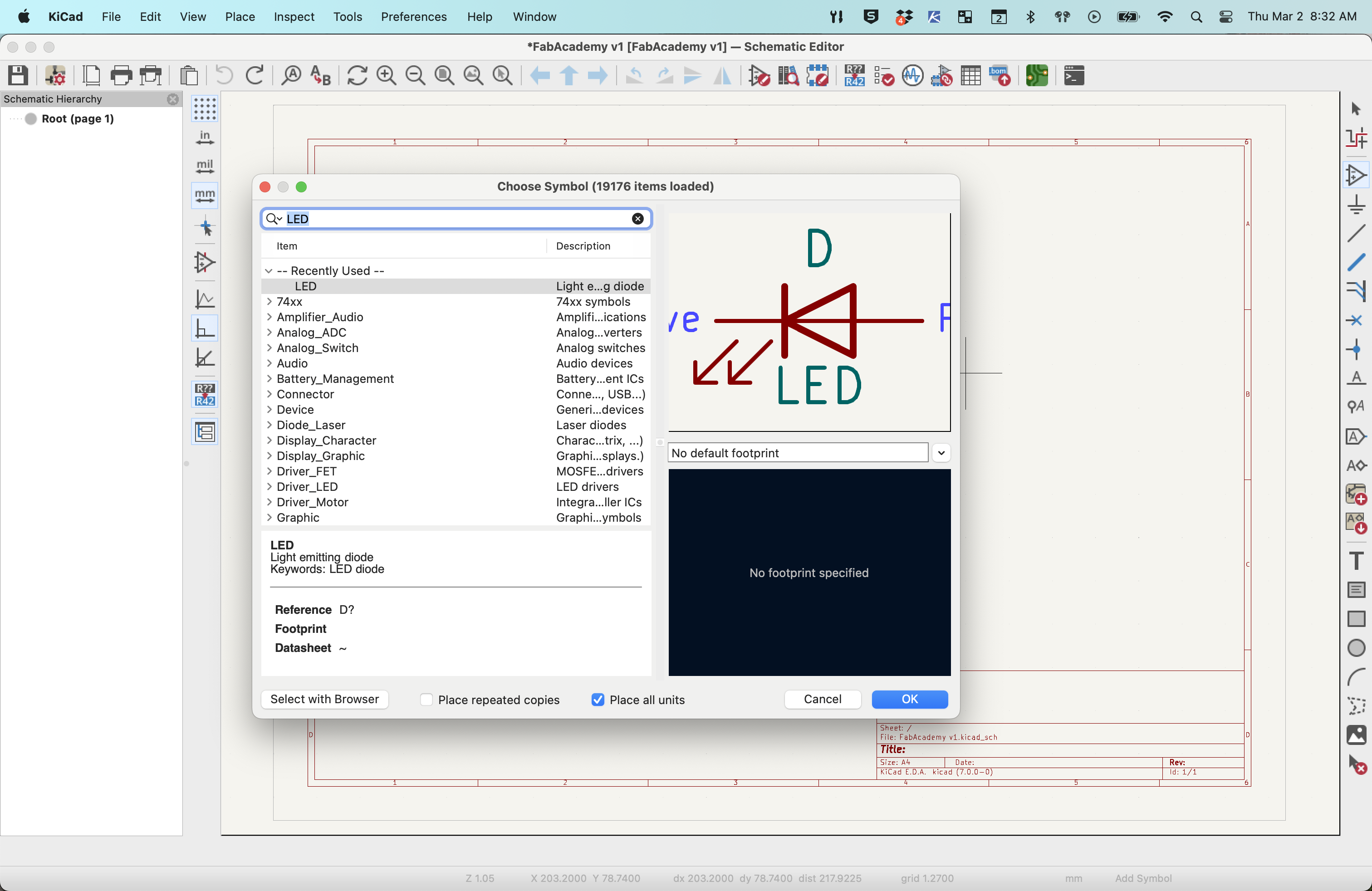
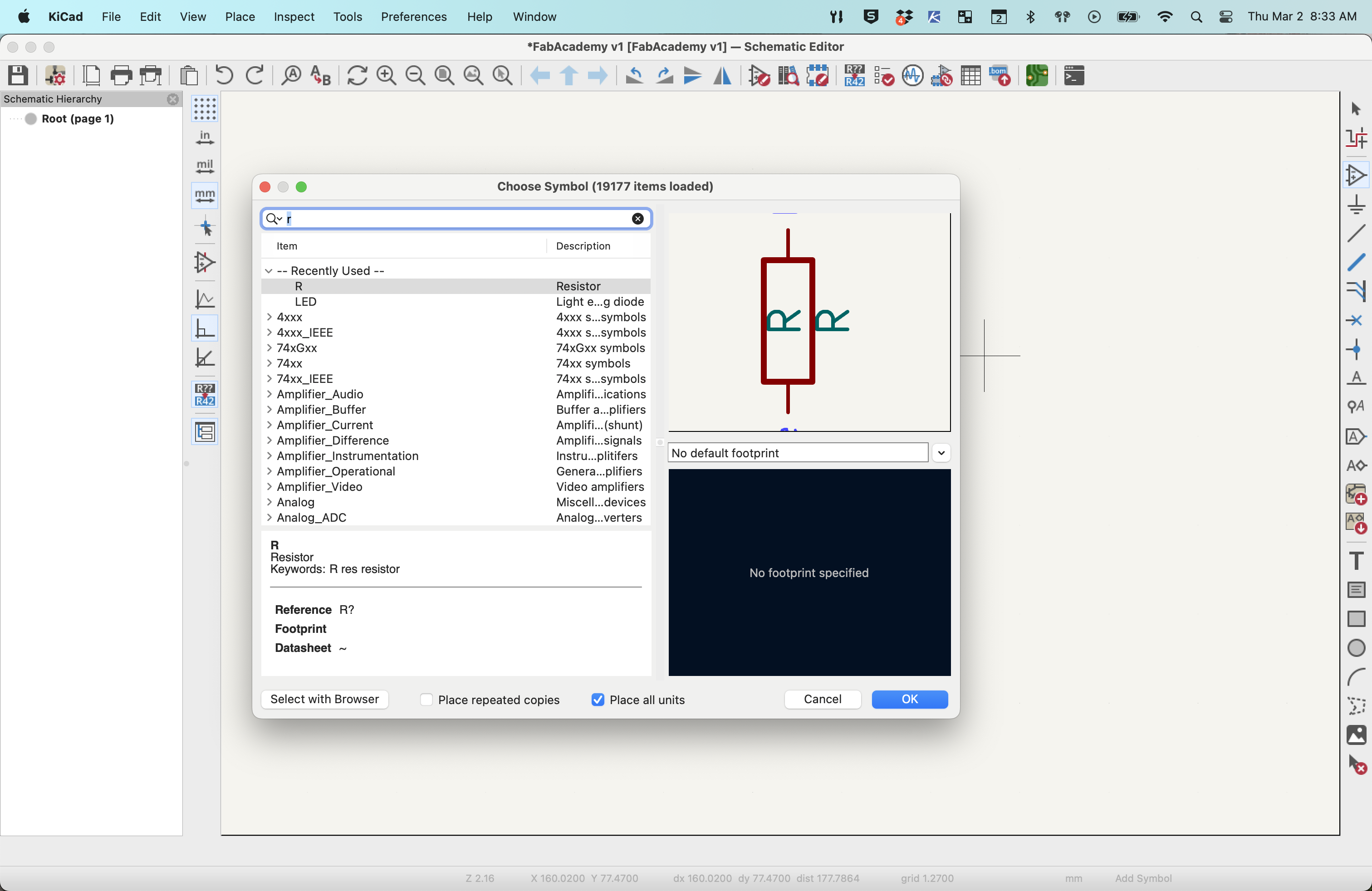
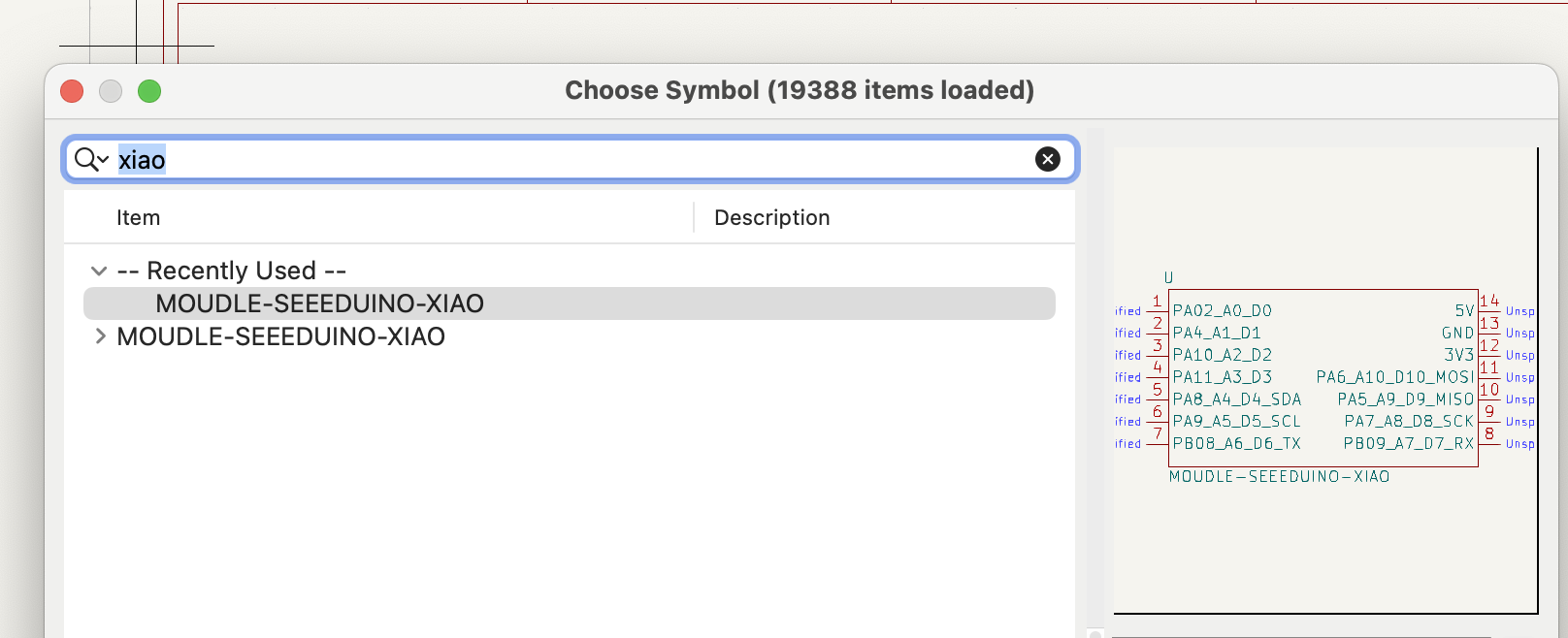
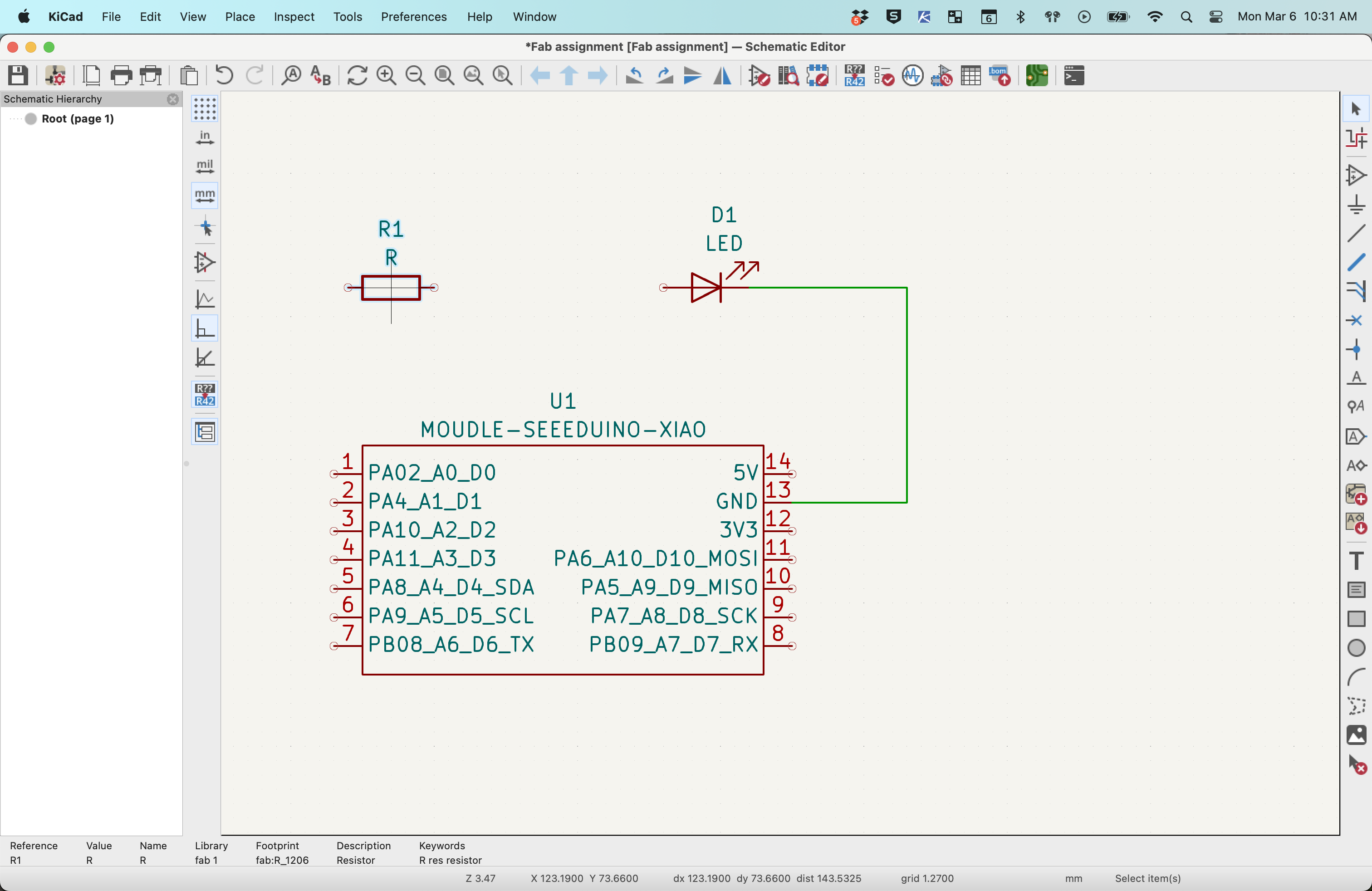
- First, select the schematic symbol for the Seeeduino-Xiao from the symbols list.
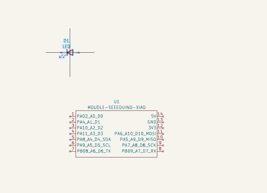
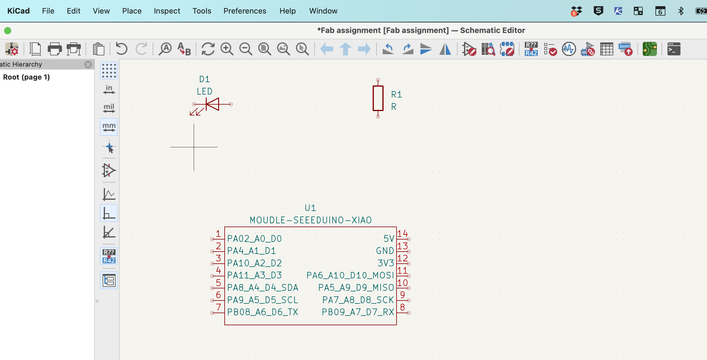
- Next, select the LED symbol and then the resistor symbol and place them in the schematic.
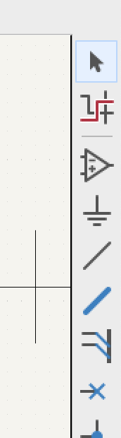
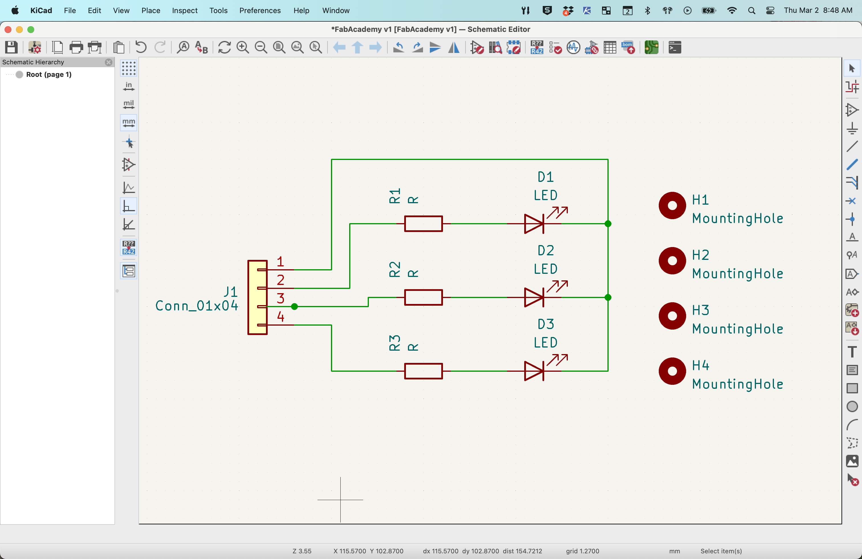
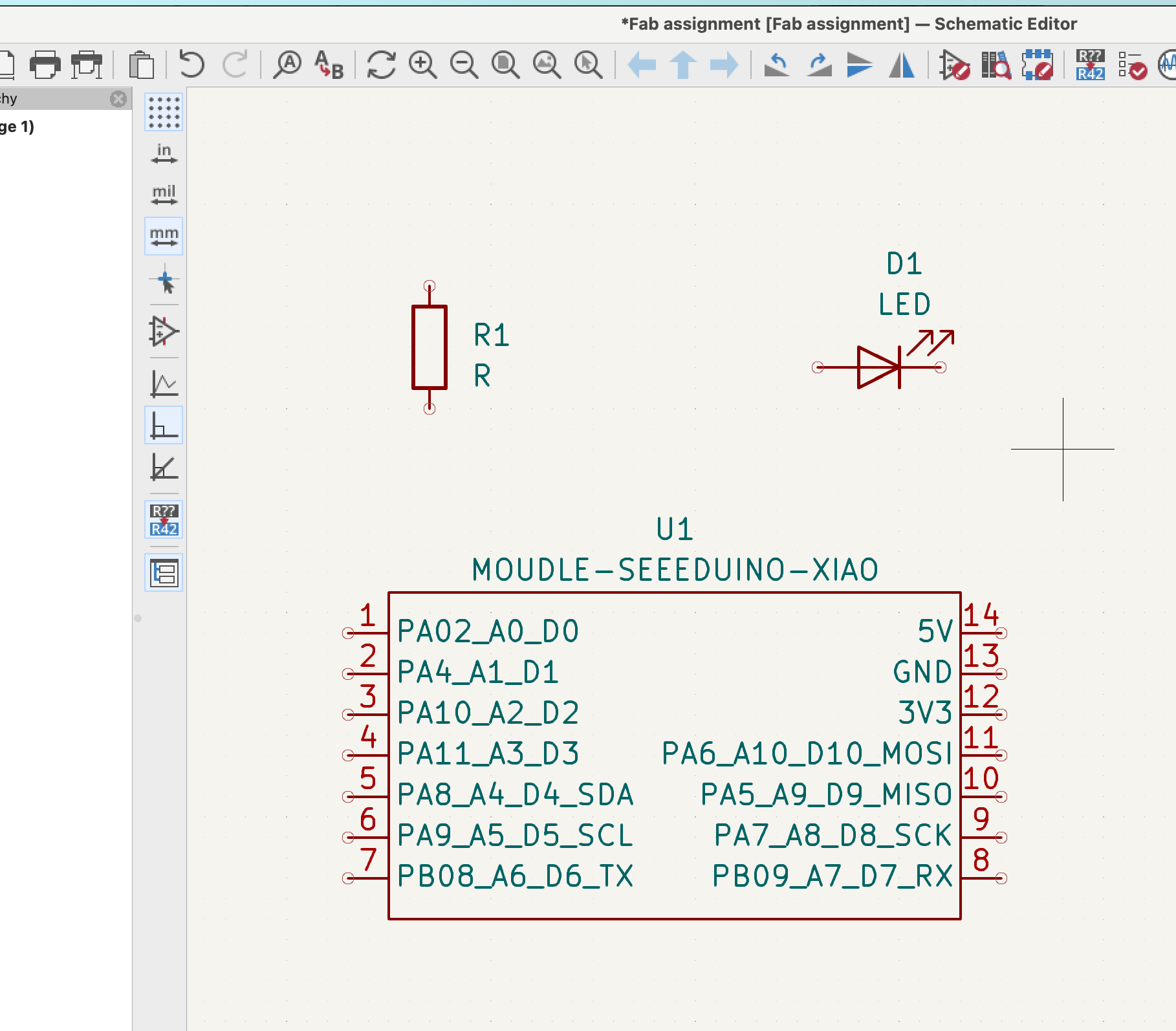
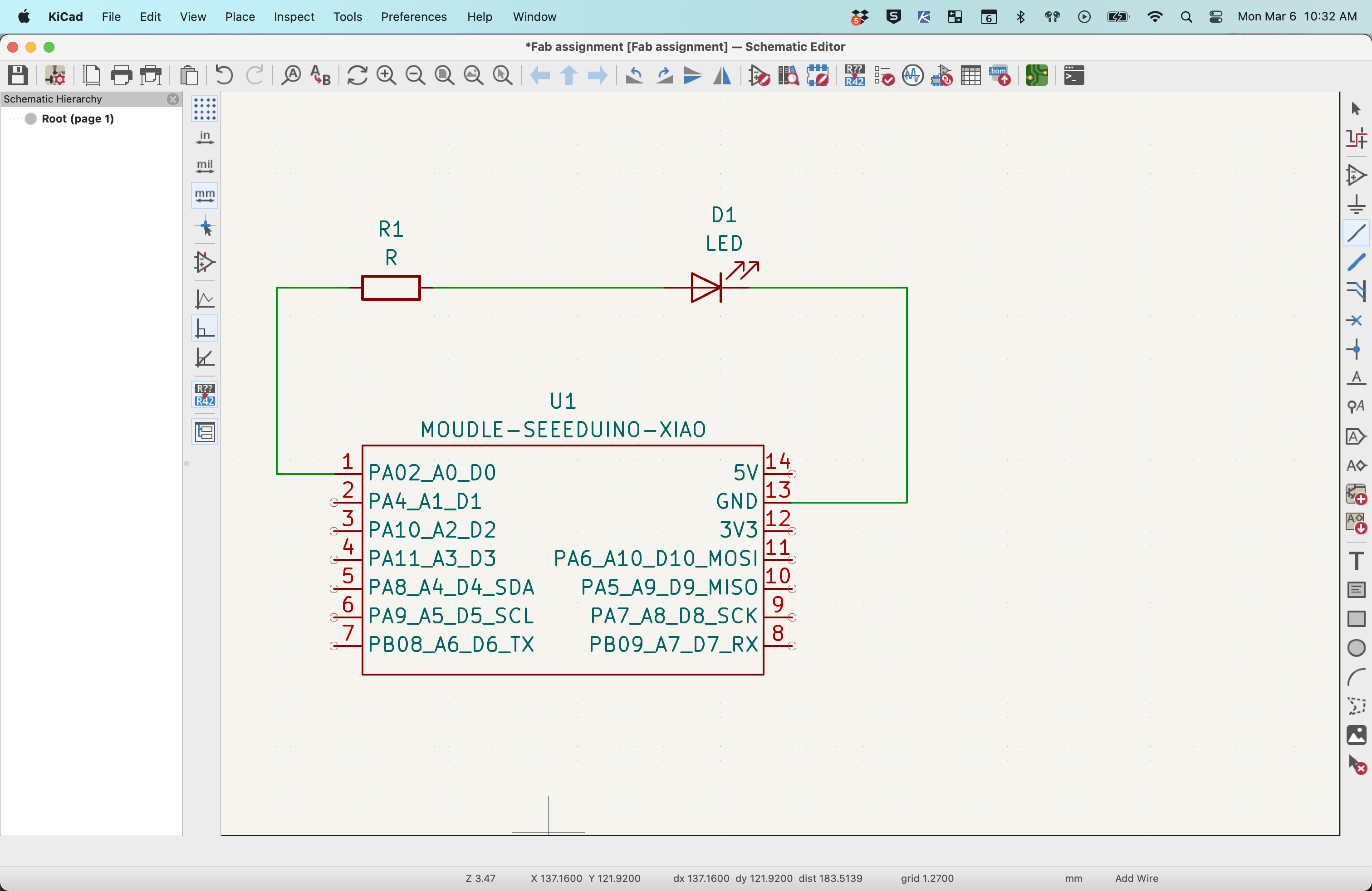
- Once all three schematic symbols are placed use the "add a wire" tool to "wire up" the circuit Be sure to pay attention to the cathode and anode ends of the LED and ground on the Seeedunio.
- Once all three schematic symbols are placed use the "add a wire" tool to "wire up" the circuit Be sure to pay attention to the cathode and anode ends of the LED and ground on the Seeedunio.
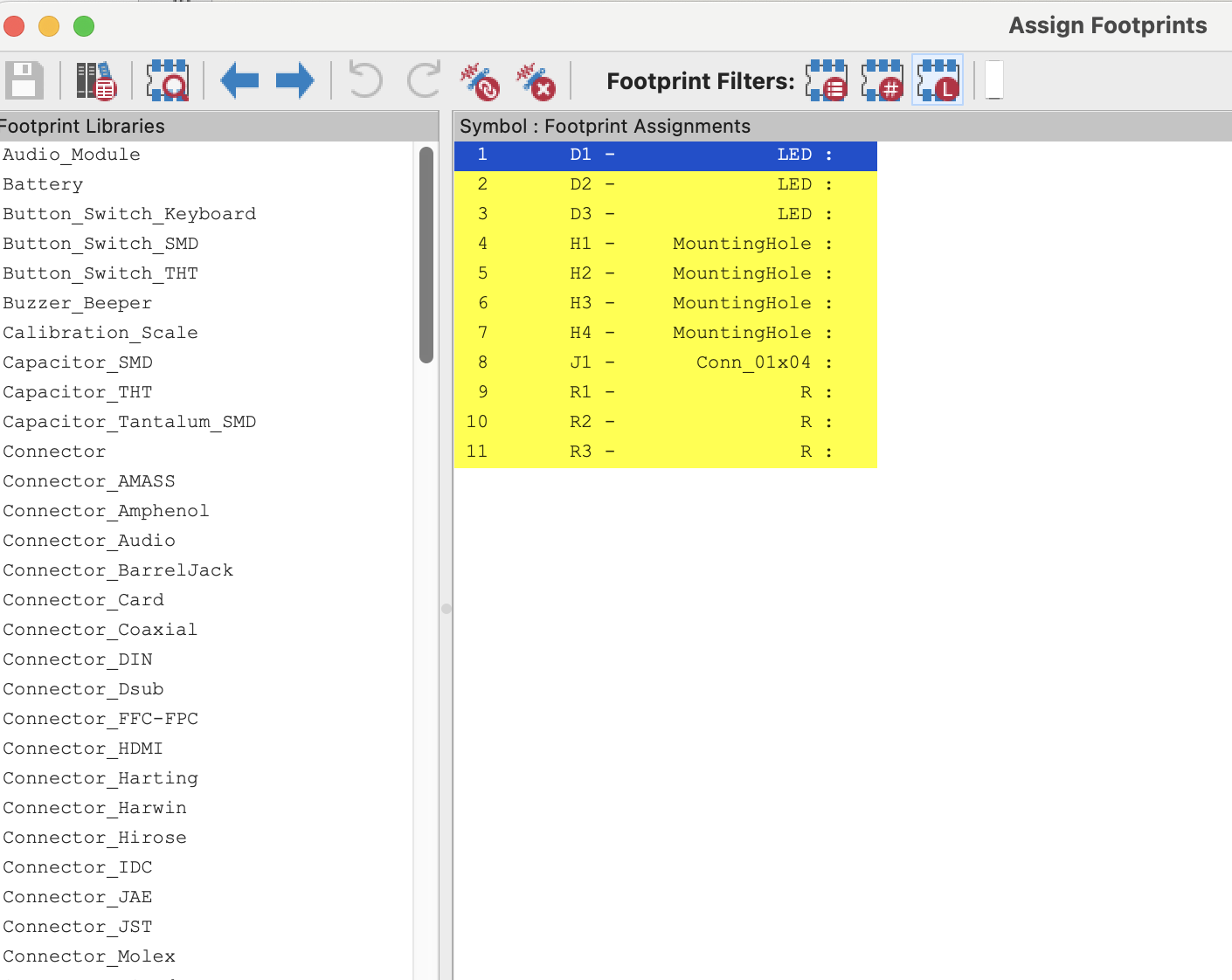
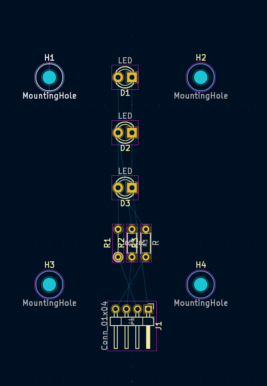
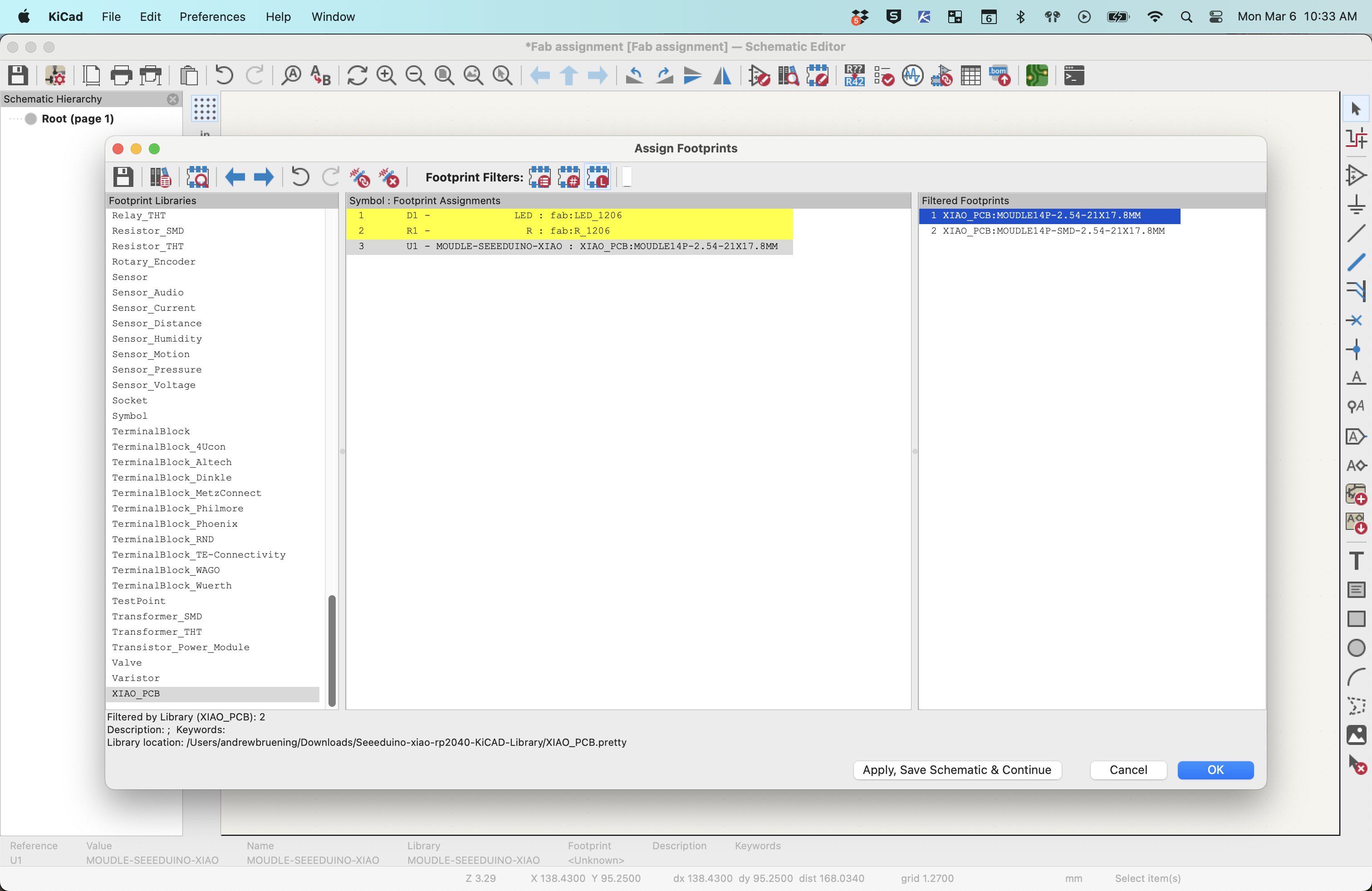
- After the symobls are placed and the wires are connected, edit/add footprint for each component.
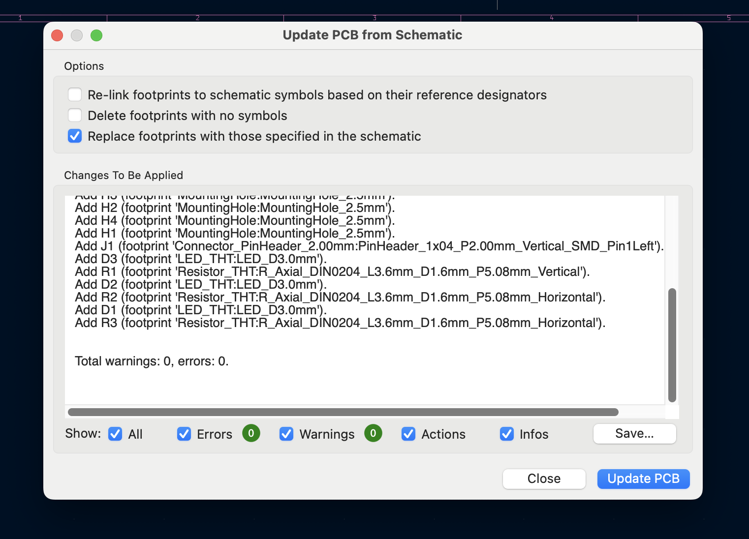
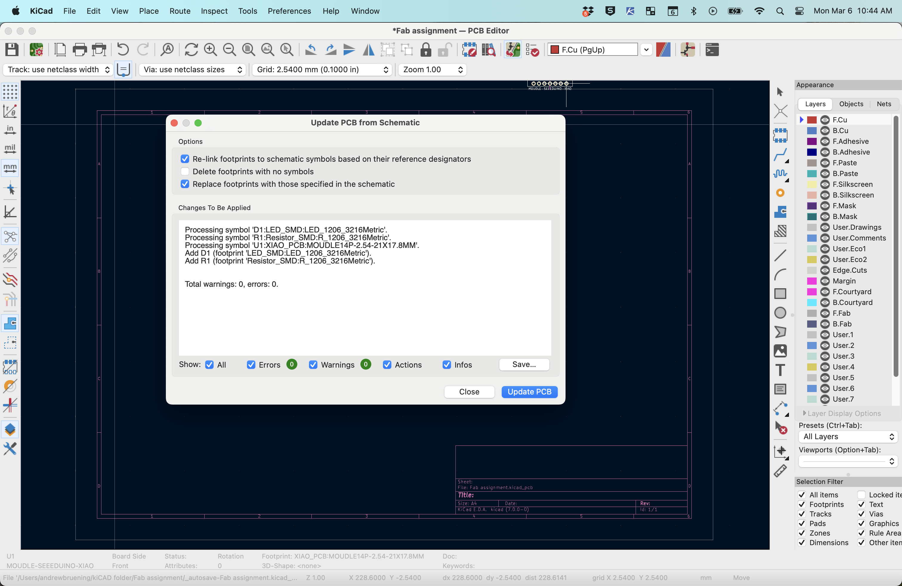
- After footprints are added, open the PCB board editor and update the footprints.
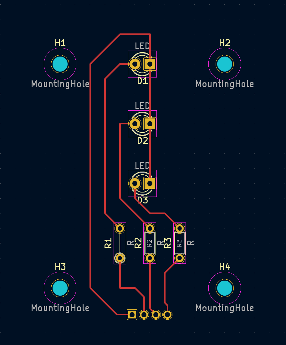
- Be sure to rearrange each component so that the trace lines to not cross over each other. Also make sure to select the F. Cu layer as you add the route tracks.
- After traces are laid out select the edge cut layer to create the edge of the PCB.
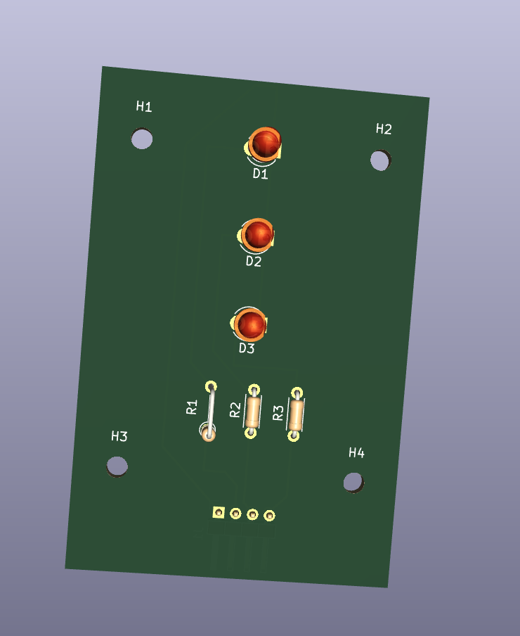
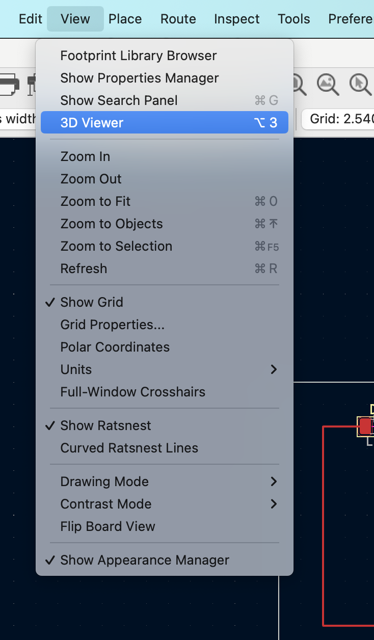
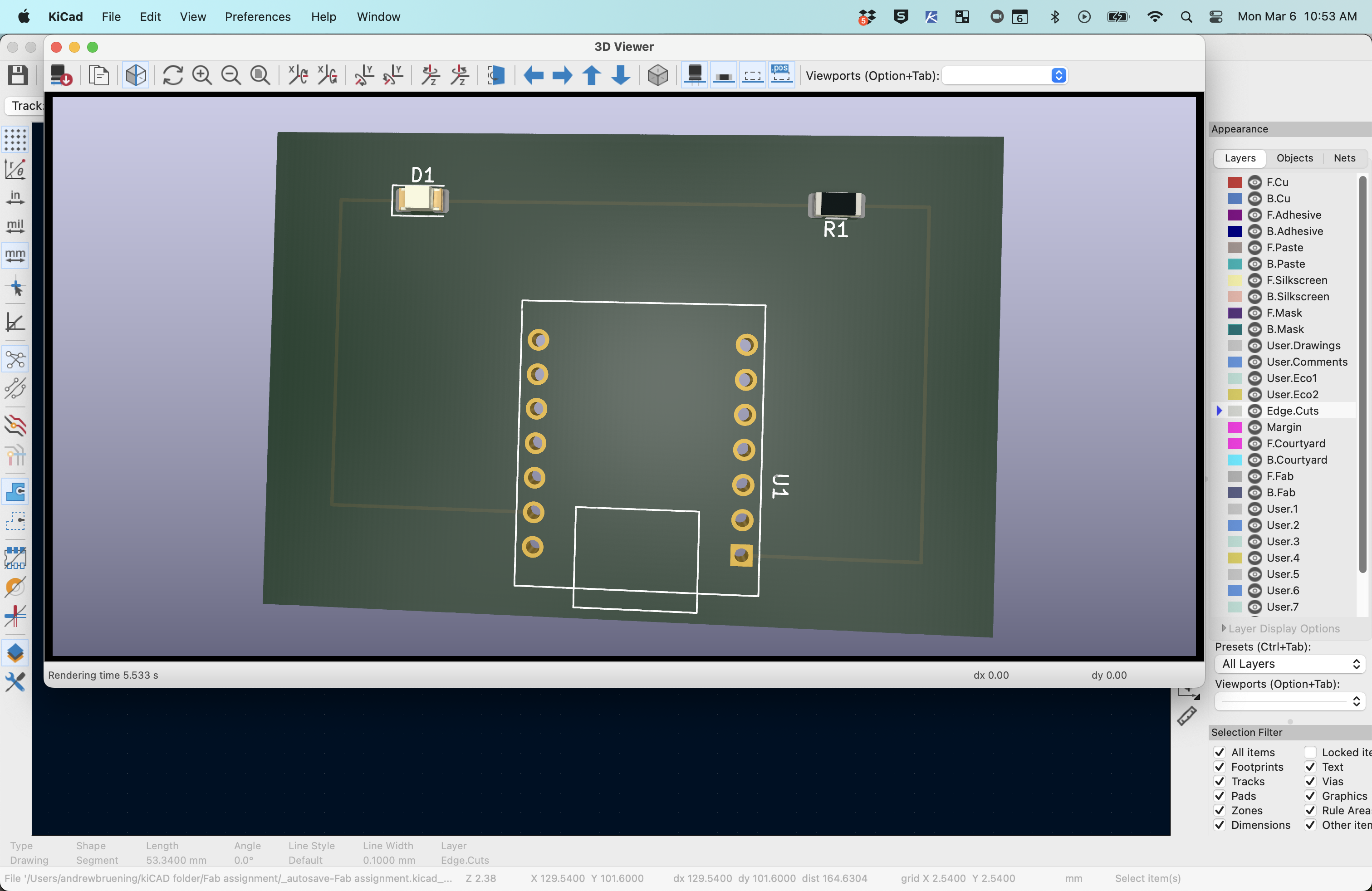
- Under the VIEW tab select 3D Viewer to see the virtual PCB.