Assignment
Individual Assignment:
- Measure something: add a sensor to a microcontroller board that you have designed and read it.
Group Assignment:
Link to Group Work- Measure the power consumption of an output device.
This week, again we are using Kelleigh's board to test the input's digital signal. Consistency is key! We are using the HC-SR04 ultrasonic sensor. This sensor has the ability to detect the distance between itself and an object. We will use this to generate an input that the computer reads. The HC-SR04 has 4 pinouts; the VCC, Trig, Echo, and GND. The VCC connects to the 5V pinout of my microcontroller - provides power. GND is connected to ground to create the electrical circuit loop. The Trig and Echo pins connect to any digital pin on my microcontroller. Trig pin receives the control signal from Arduino (pulse), and Echo sends a signel (pulse) to Arduino. Arduino then measures the duration of pulse to calculate distance. To do this, we touch the black probe to the ground pin on the sensor, and the red probe to the VCC pin on the sensor. This gave us a reading for how much power is reaching the sensor. This reading was 4.98 V. Because we do not have an oscilloscope, the testing we can do is limited. Images for this week are found on Kelleigh's page. See Link to Group Work above.
Individual Assignment
Measure something: add a sensor to a microcontroller board that you have designed and read it
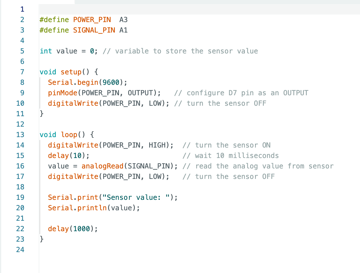
- For the assignment this week I used the microcontroller I created in Week 8 and added water or moisture sensor.
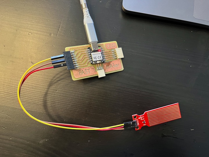
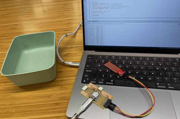
- I began by wiring up the water sensor and writing code for it to measure moisture. I wired the signal from sensor to A1 on the RP2040 and the positive from the sensor to A3 and negative to ground on the RP2040.
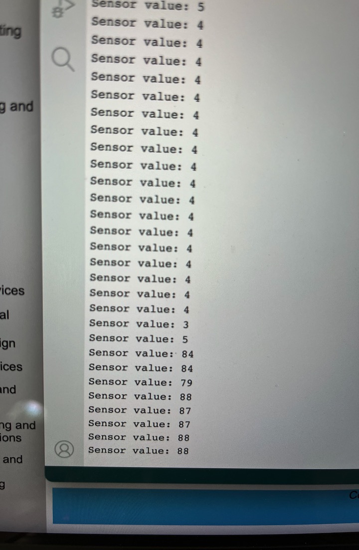
- Next, I slowly dipped the sensor in a glass of water and the serial monitor gave the moisture reading.
- Once eveything was set up and programmed it was actually fairly easy to get it all to work.
The images below.
Initial set up to test system.
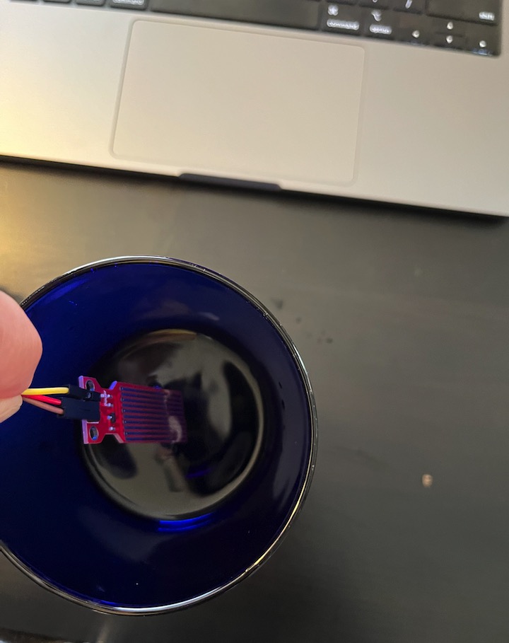
Hero shot of input device