Input Devices
Individual Assignment
This week we are tasked with measuring something: adding a sensor to a microcontroller board that we have designed and read it.
Group Assignment
Link to Group Page Our group task this week is to probe an input device's analog levels and digital signals.
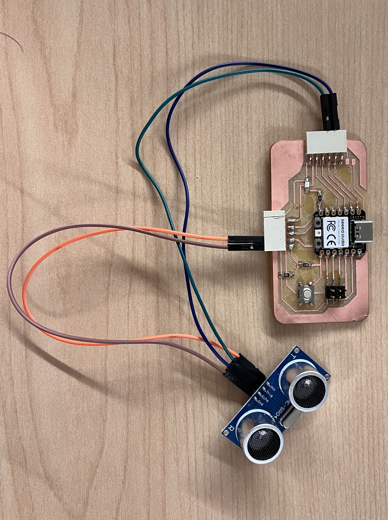
This week, again we are using Kelleigh's board (me) to test the input's digital signal. Consistency is key! This week we are using the HC-SR04 ultrasonic sensor. This sensor has the ability to detect the distance between itself and an object. We will use this to generate an input that the computer reads. The HC-SR04 has 4 pinouts; the VCC, Trig, Echo, and GND. The VCC connects to the 5V pinout of my microcontroller - provides power. GND is connected to ground to create the electrical circuit loop. The Trig and Echo pins connect to any digital pin on my microcontroller. Trig pin receives the control signal from Arduino (pulse), and Echo sends a signel (pulse) to Arduino. Arduino then measures the duration of pulse to calculate distance.
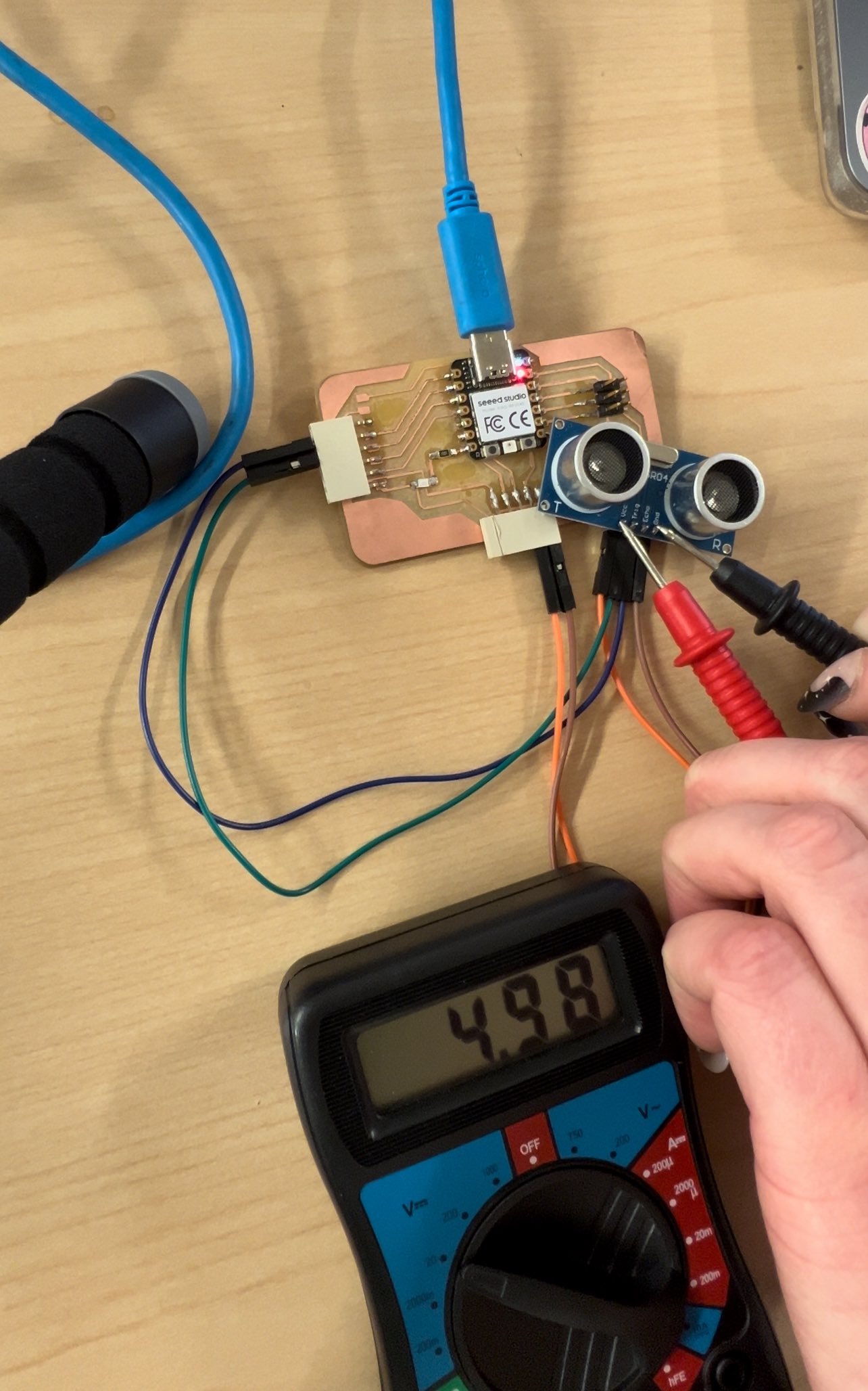
To do this, we touch the black probe to the ground pin on the sensor, and the red probe to the VCC pin on the sensor. This gave us a reading for how much power is reaching the sensor. This reading was 4.98 V.
Because we do not have an oscilloscope, the testing we can do is limited.
Group Assignment Part 2...
If you are looking to follow along and probe an input sensor then follow this section here, not the one above this. I was not fully knowledgable about how to measure current and resistance of a sensor before but with some help (Shoutout to Eduardo) I was able to follow a page on an LDR sensor from DIYEngineer.com and (hopefully) complete this assignment.
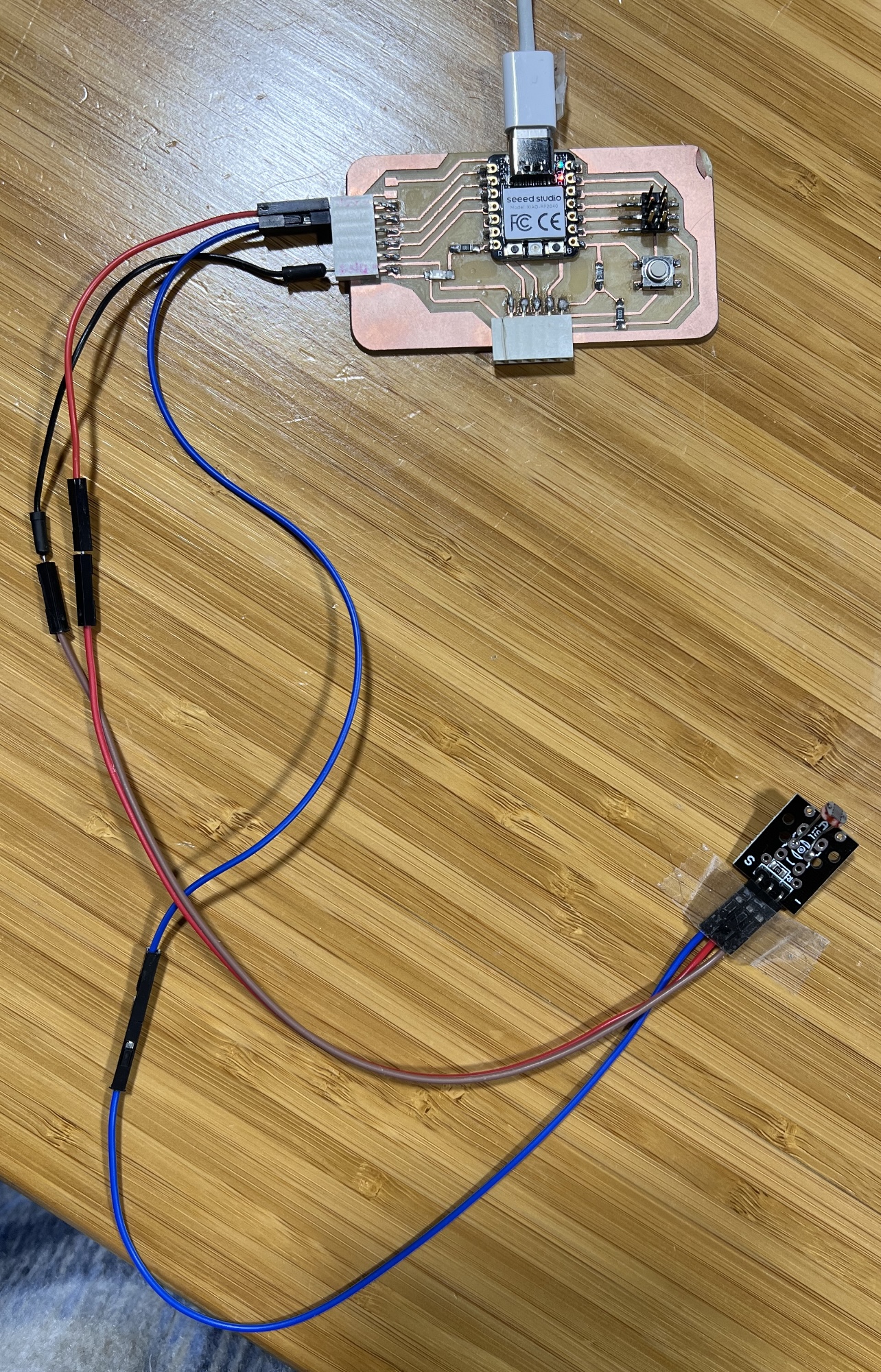
I will be using the microcontroller PCB that I designed and produced in house, an LDR sensor, wires, and a multimeter. The set up is quite simple but on the Fab Academy page it is said that we are not supposed to use breadboards, so my setup differs slightly from the webpage I have linked to above. The VCC pin on the LDR connected to my 5V pin, the GND went to my ground on my board, and the signal pin went on the A0 analog pin of my board.
The Arduino Code I used was actually from another website I used to help me with the group assignment, RoboIndia.com. The code was easy to read and it translated well for the outcome I desired (just reading the outputs with a multimeter). I will post the code I used below.
         // Robo India's Tutorial on LDR.
         // http://roboindia.com/


         int LDR = A0;            // LDR input at A0 pin.
         int LED = 3;             // LED is connected to PWM Pin 3.
         int LDRReading = 0;      // to store input value of LDR
         int lEDBrightness = 0;   // to store the value of LED Brightness
         int threshold_val = 800; // Check your threshold and modify it.

         void setup(){
           Serial.begin(9600);     // initializing serail communication.
           pinMode(LED, OUTPUT);   // Defining LED pin as output.
         }

         void loop(){
           LDRReading = analogRead(LDR);    // Reading LDR Input.
           Serial.println(LDRReading);      // Printing LDR input value.

           if (LDRReading >threshold_val){                   // Condition to make LED ON.
           lEDBrightness = map(LDRReading, 0, 1023, 0, 255); // Converting LDR to LED Brightness.
           analogWrite(LED, lEDBrightness); // Writing Brightness to LED.
           }
           else{
           analogWrite(LED, 0);             // If LDR is below threshold make LED OFF.
           }

           delay(300);                      // delay to make output readable on serial monitor.
         }
From the pictures, you can see I do not have an LED or anything additional with my LDR. From reading the code, I was pretty confident it would work for the serial monitor, which is what I needed. And it did end up working just fine for me.
The table below shows the values I was given from the Arduino IDE serial monitor output, and the multimeter readings of the LDR. I probed the LDR by using the red VCC probe on the multimeter and touching it to the exposed metal section of the signal wire the LDR is connected to. The black plastic connectors have the perfect spot where the signal metal is exposed, and you can simply touch the probe to it. The ground probe on the multimeter I touched to the ground pin on my board itself, because it was the most stable place for me to keep my connection steady.
| Light Condition | Serial Monitor Value | Multimeter Resistance |
|---|---|---|
| Phone Flashlight | 51 | 0.559 MOhms |
| Standard Room Light | 209 | 13.63 MOhms |
| Shadowed Room Light/Dark | 657 | 24.89 MOhms |
The voltage consumption was the greatest when the LDR picked up the brightest light. The increase in values from the multimeter is due to the relationship between voltage, current, and resistance. The voltage range is 0V to 5V (the max on my PCB) --> the more light the LDR reads = more voltage consumption = higher current value from the multimeter. Resistance decreases as light level increases.
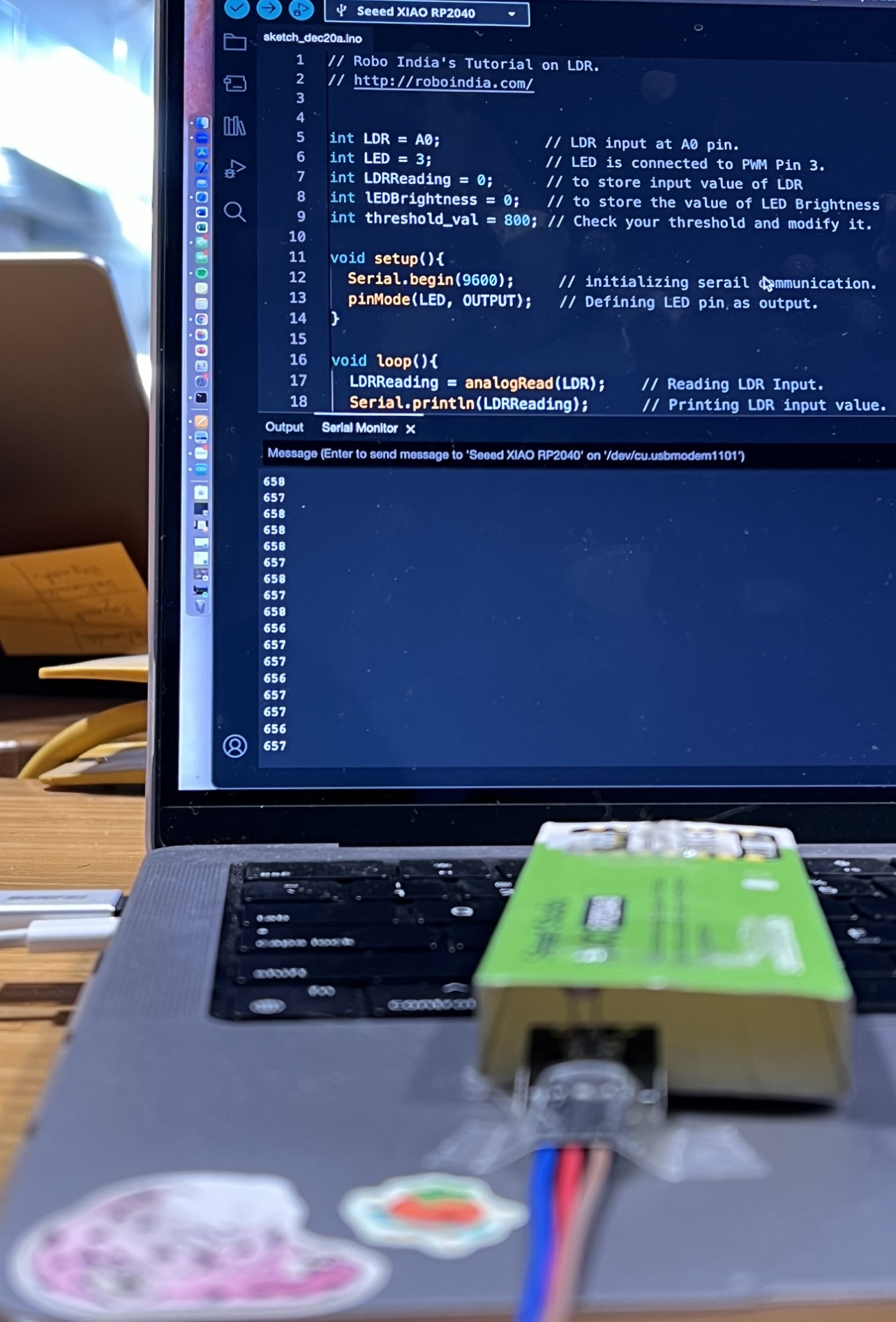
This last image is the shadowed room light I am referring to in the table. Without another arm or alligator clips it is quite difficult to shade the LDR and probe at the same time.
Other Useful Sources
- urPCB - Introductory Guide to Button Circuits
- QualiEco - Glossary and Abbreviations for Printed Circuit Boards
- Adrian Torres - FabXIAO page
Individual Assignment
To start my individual assignment I needed to know which input device I wanted to work with. I didn't have much time on my hands this week so I made it something relatively easy.. a button. I opened Kicad and started designing a circuit, with the help of the resources I listed above.
Kicad
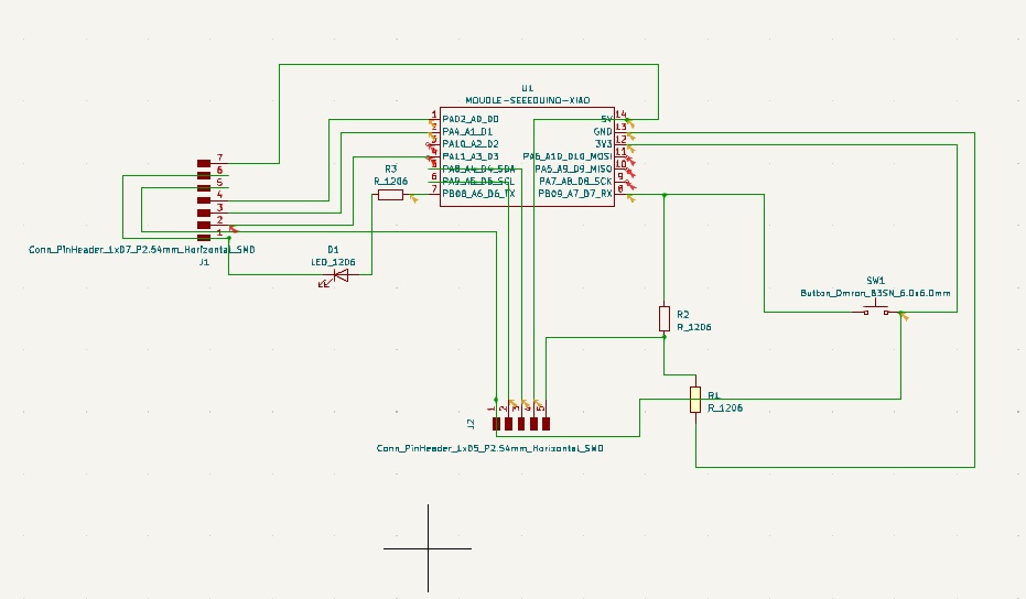
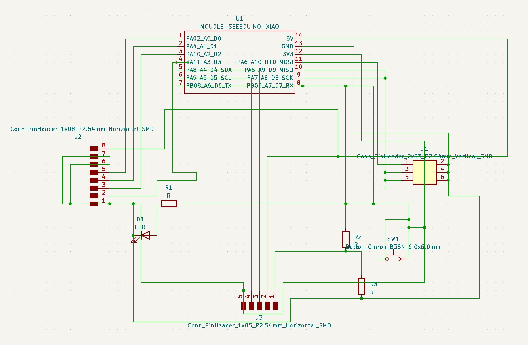
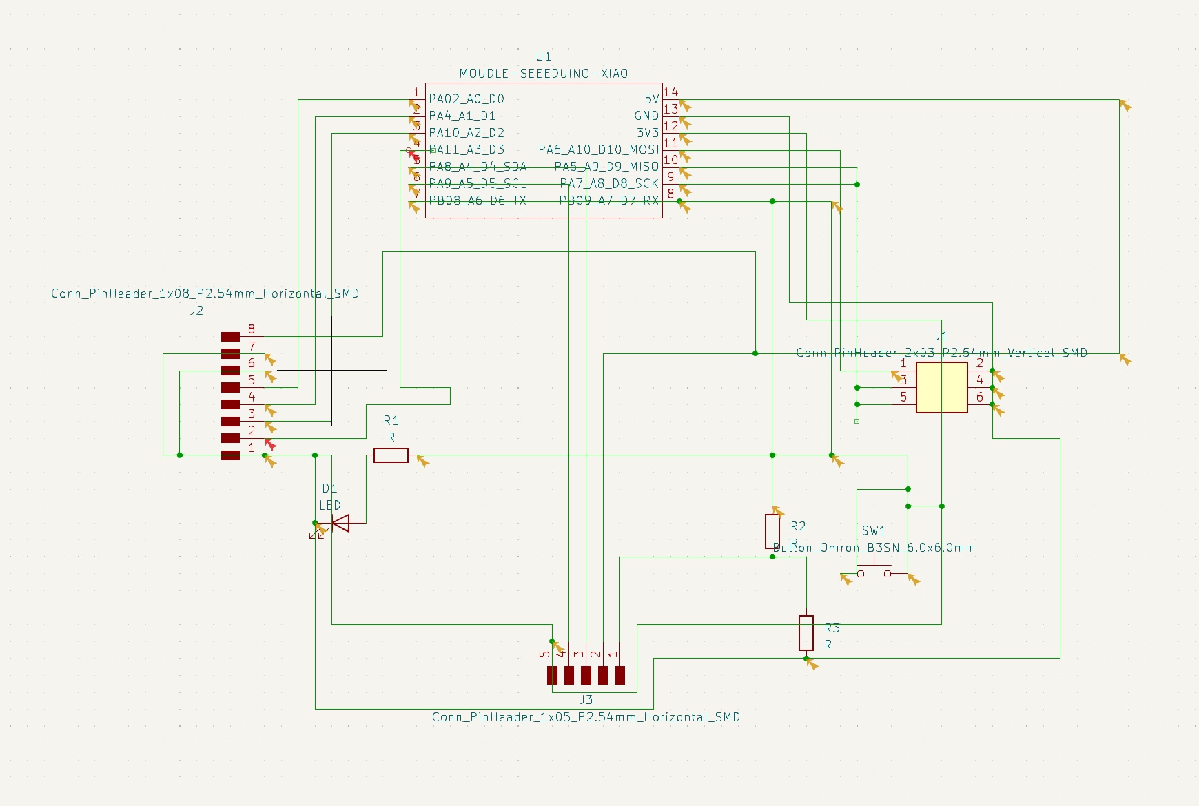
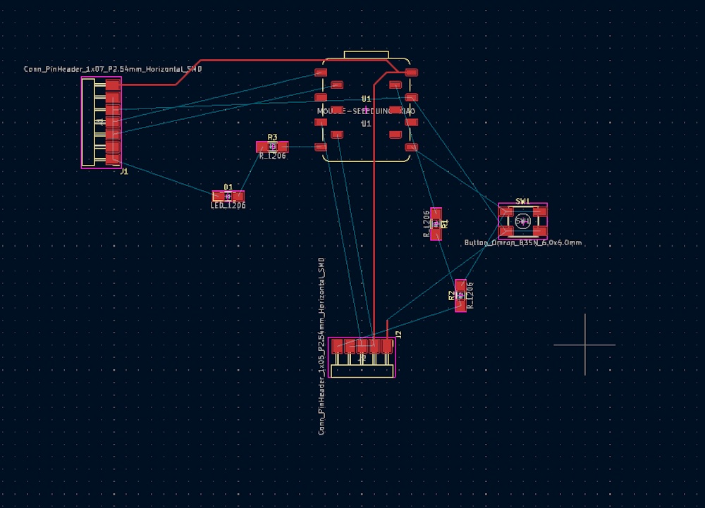
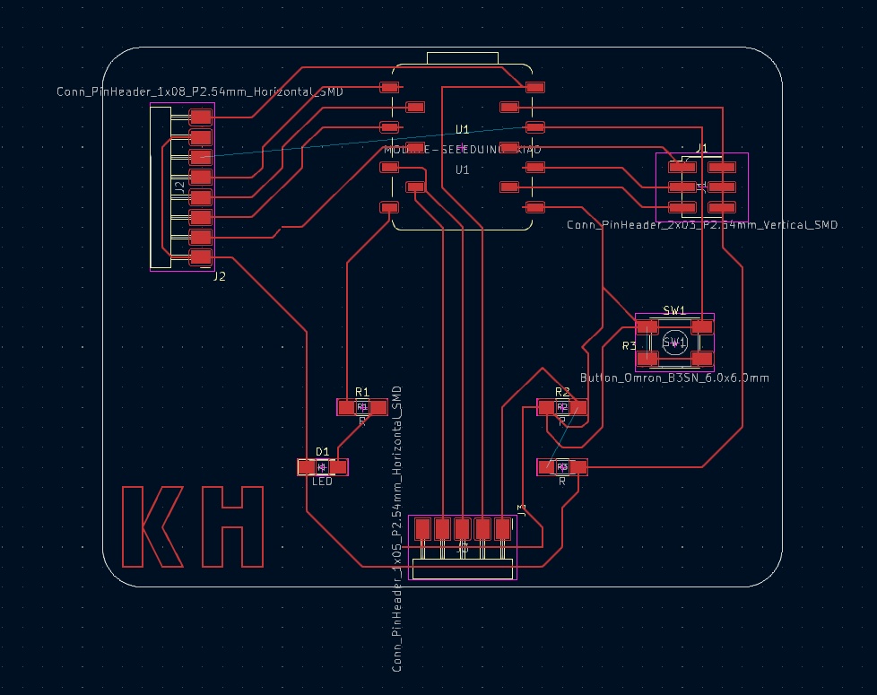
Kicad
The above photos summarize my work on Kicad. To learn more about how to use Kicad to produce PCB designs, you can visit my Week 6 - Electronics Design page. A basic, simplified outline of the process is:
- Research your microcontroller. Figure out is voltage, pinout, and optimal sizing for soldering onto your board.
- Download and open Kicad. Start a new project through the file dropdown. Begin in the schematic editor.
- Design your schematic, following electrical rules and keeping the desired input component in mind.
- Open your Kicad schematic in the PCB editor. Rearrange components and add routes for your copper tracks.
- Once your design is as desired, export the file as an SVG. At PAST, we must put this on a flashdrive to go to the laptop connected to our Forest CNC machine.
- On the machine, secure your board flat to the surface. Secure with double sided tape and ensure it is level.
- Upload SVG file to FlatCAM and send the Gerber file to your machine.
- Done! You should have your PCB now. Download PCB Design Here
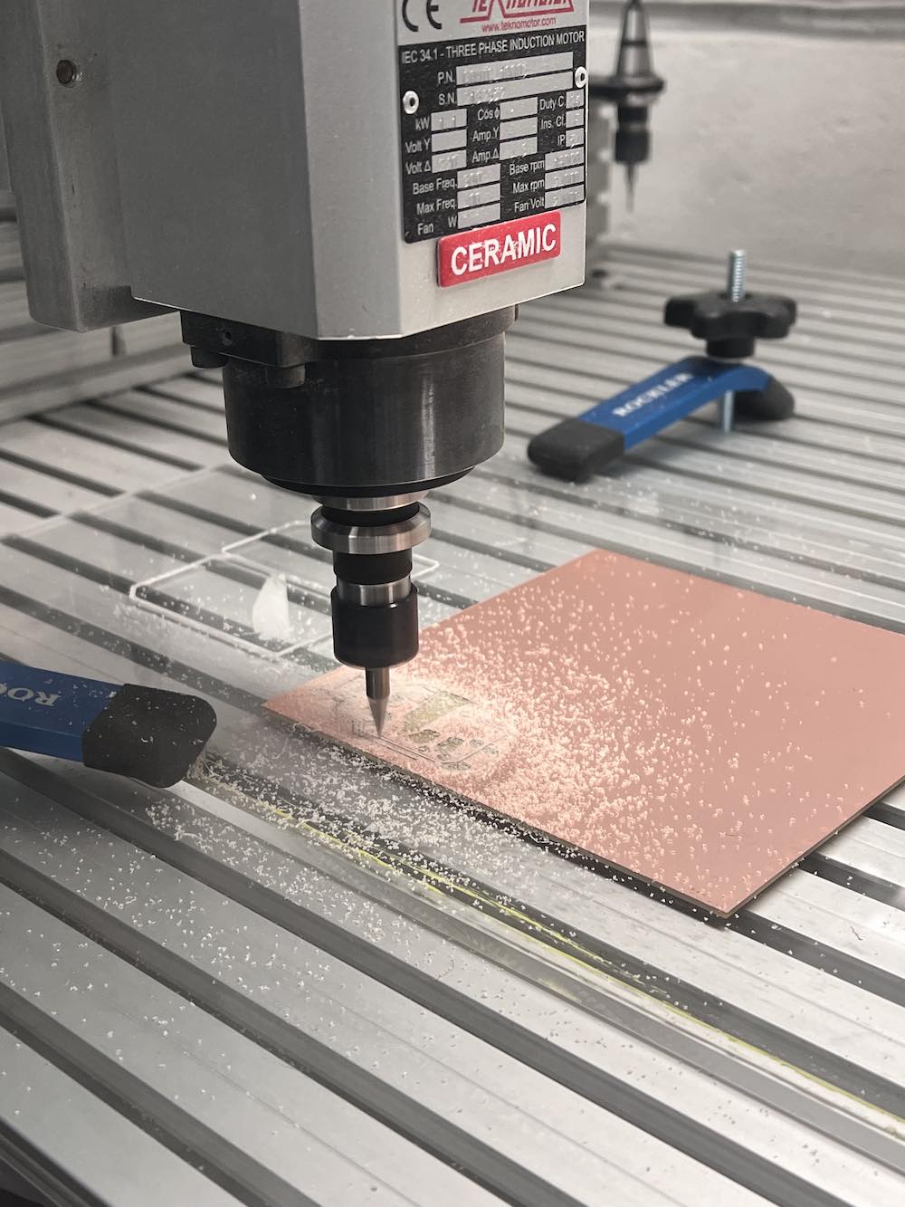
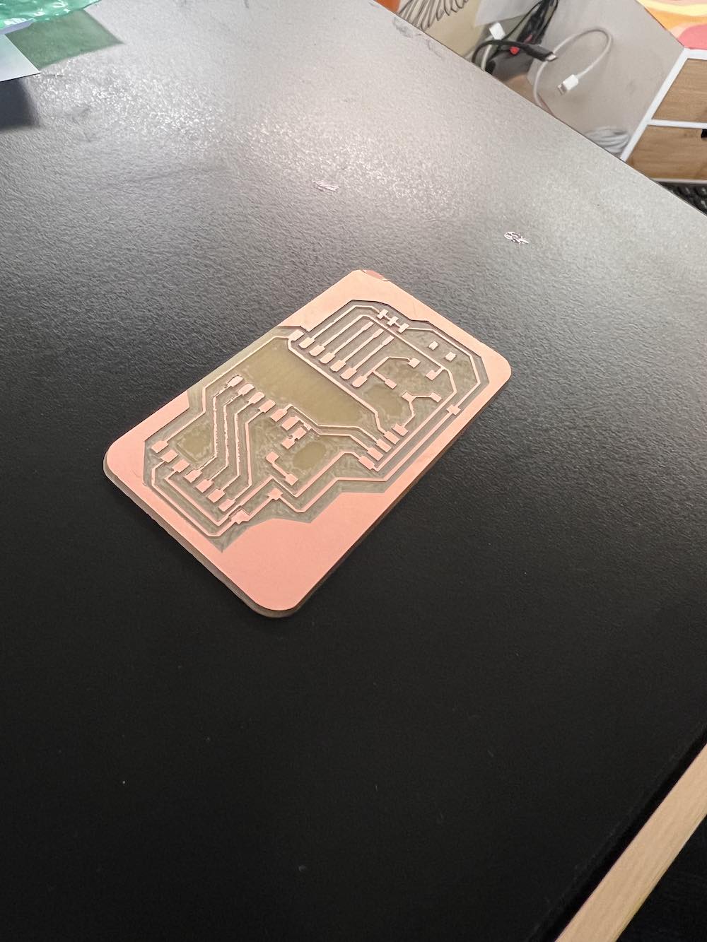
Milling
After lots of trial and error, which is documented on my Week 8 - Electronics Production page.
Using a Kicad design file, FlatCAM and our Forest CNC machine, we were able to mill a completed PCB with enough room and spacing to solder components on. Once I had my design file done, it is pretty simple to mill. Using FlatCAM, convert your SVG to a Gerber file, this is readable by the machine. Once you secured your board to the milling area with double sided tape and ensured it is level, you start milling your design. The machine will do all the work for you. Once the machine comes to a complete stop, you can remove the milled board and clear off the dust. Next, you move on to soldering!
Soldering
The images below are our current materials in our soldering station. It is equipped with
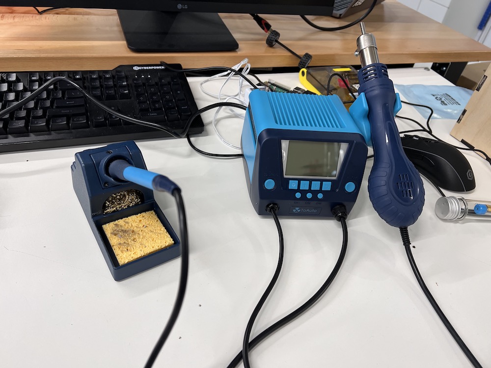
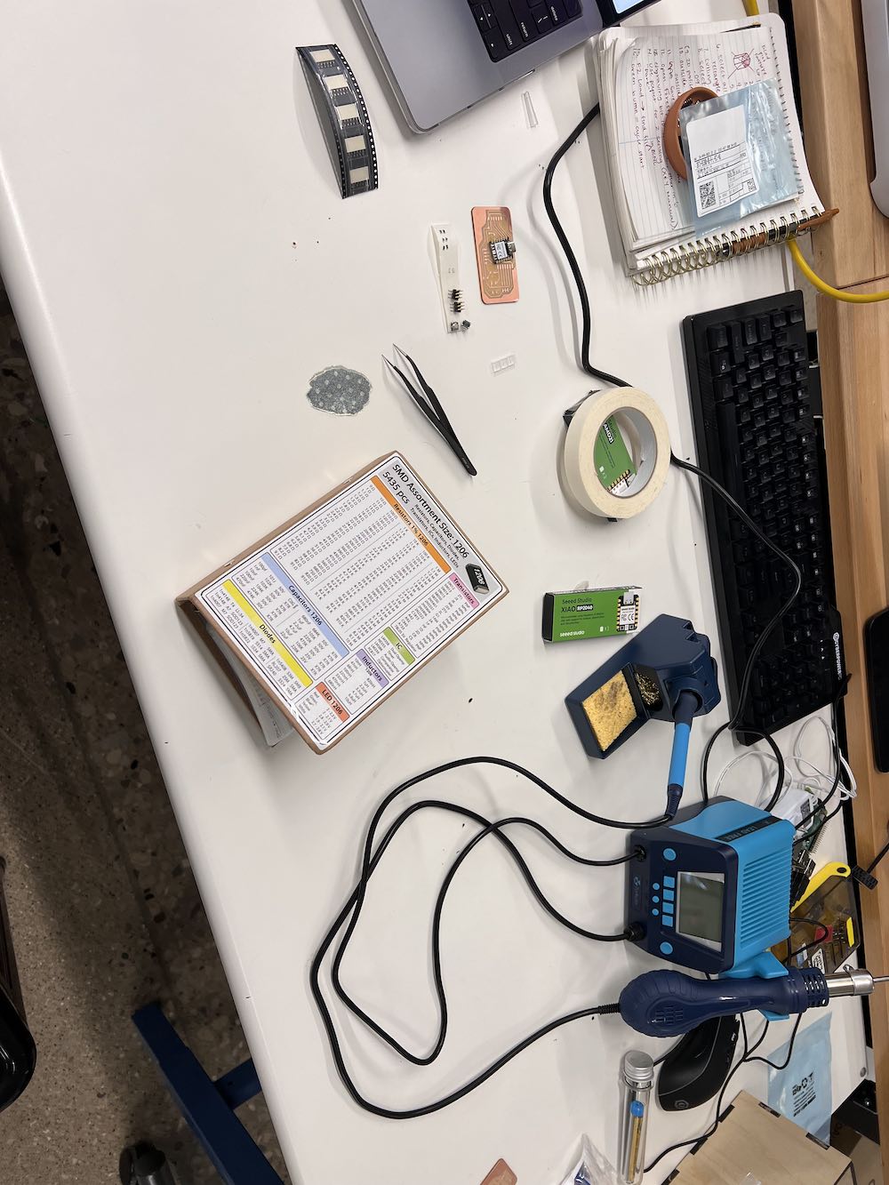
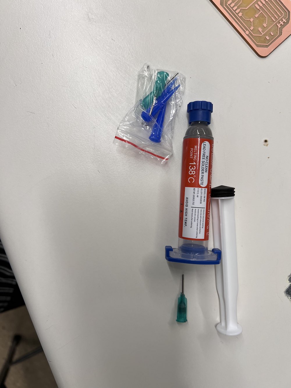
Soldering Paste
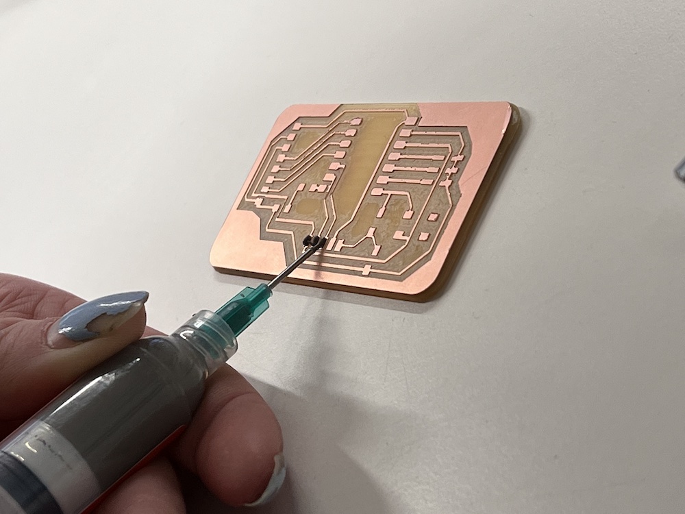
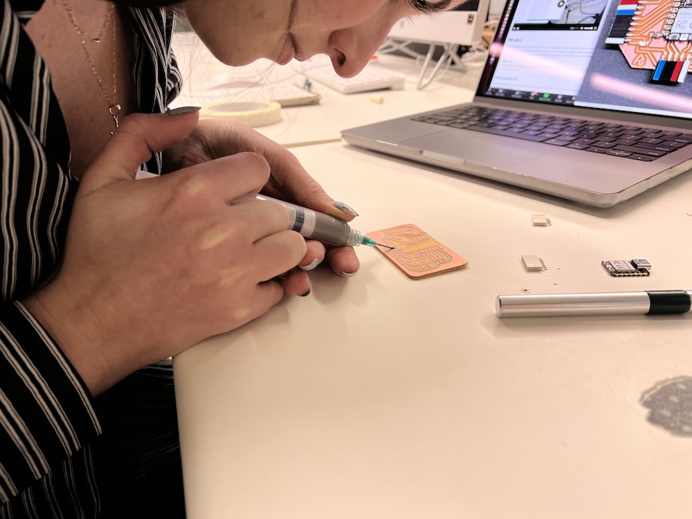
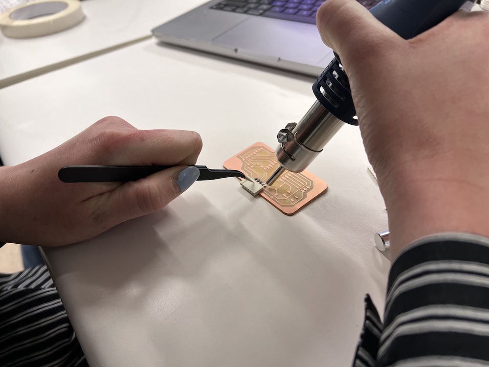
I initially started to solder my board using soldering paste. To do this, you first make sure your board is all wiped down and theres no excess dust. Place a small strip of soldering paste onto the desired pad area. Use tweezers to pick up your component you want to attach. Grab the heat gun with the other hand. Place the component on the strip of placed soldering paste and put the heat on to begin melting it. Once your paste gets a shiny, wet textured look, it is melting! It unfortunately was very difficult to work with for me personally, so I switched to the soldering wire.
Soldering Wire
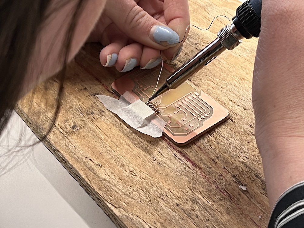
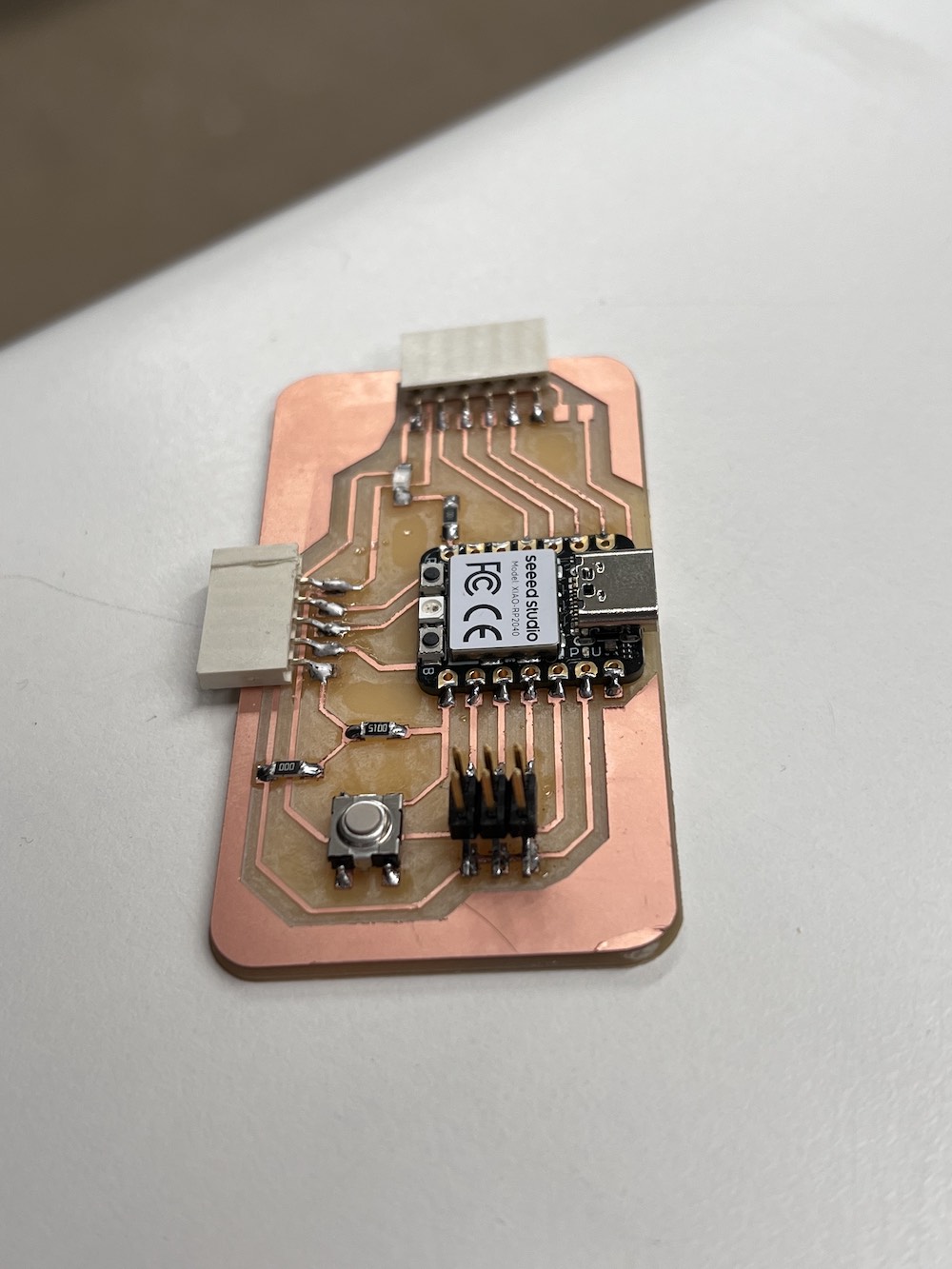
Once I switched to soldering wire, it was much easier to solder my components on. First, place your component in the desired spot. Hold the wire in one hand, and the soldering iron in the other. Place the wire on the connecting point between your pad on your PCB and your component. Touch the iron to the wire to make a bead of metal that will attach and connect the two parts. Do this for each component and each pad to complete your board!
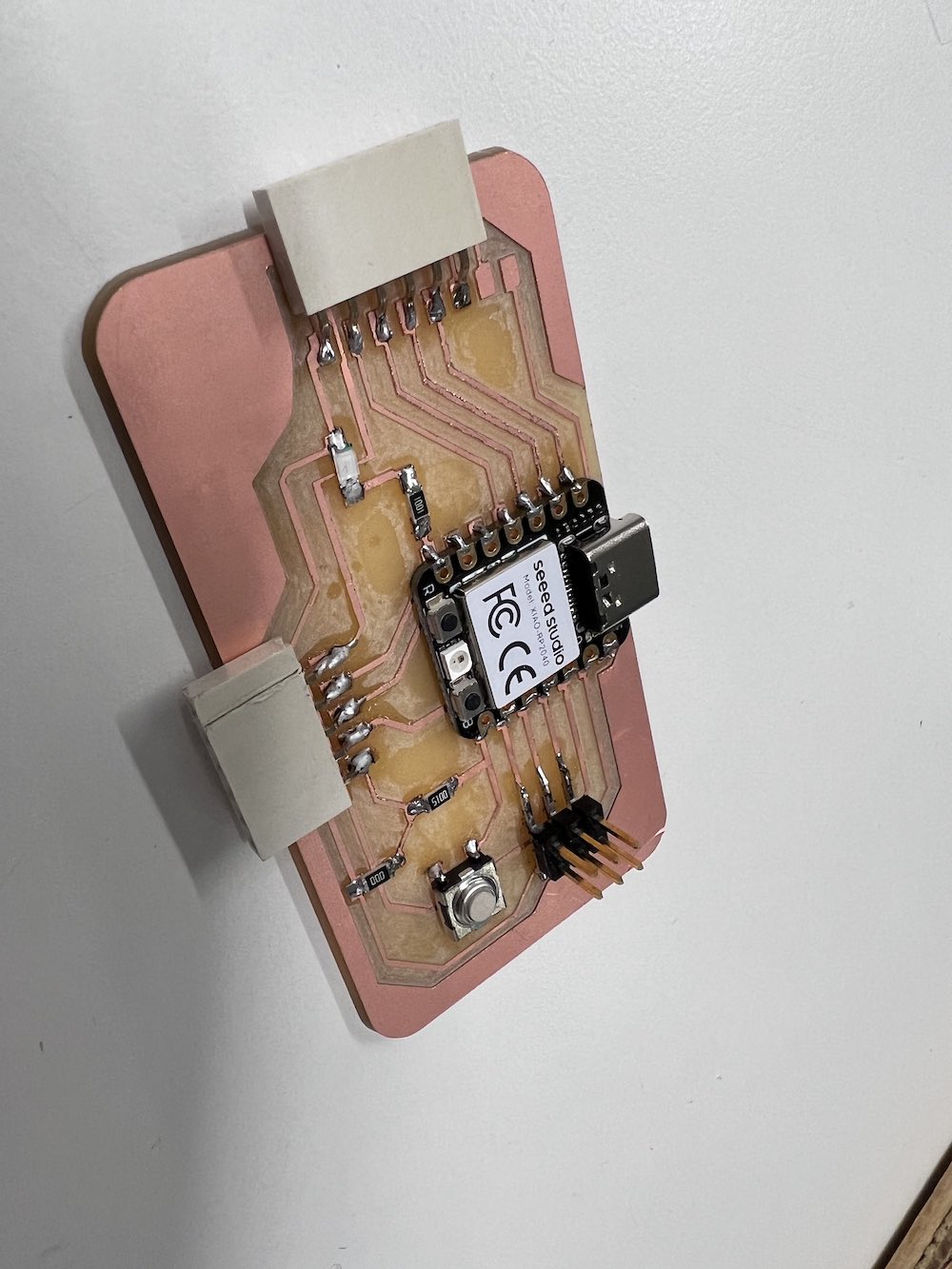
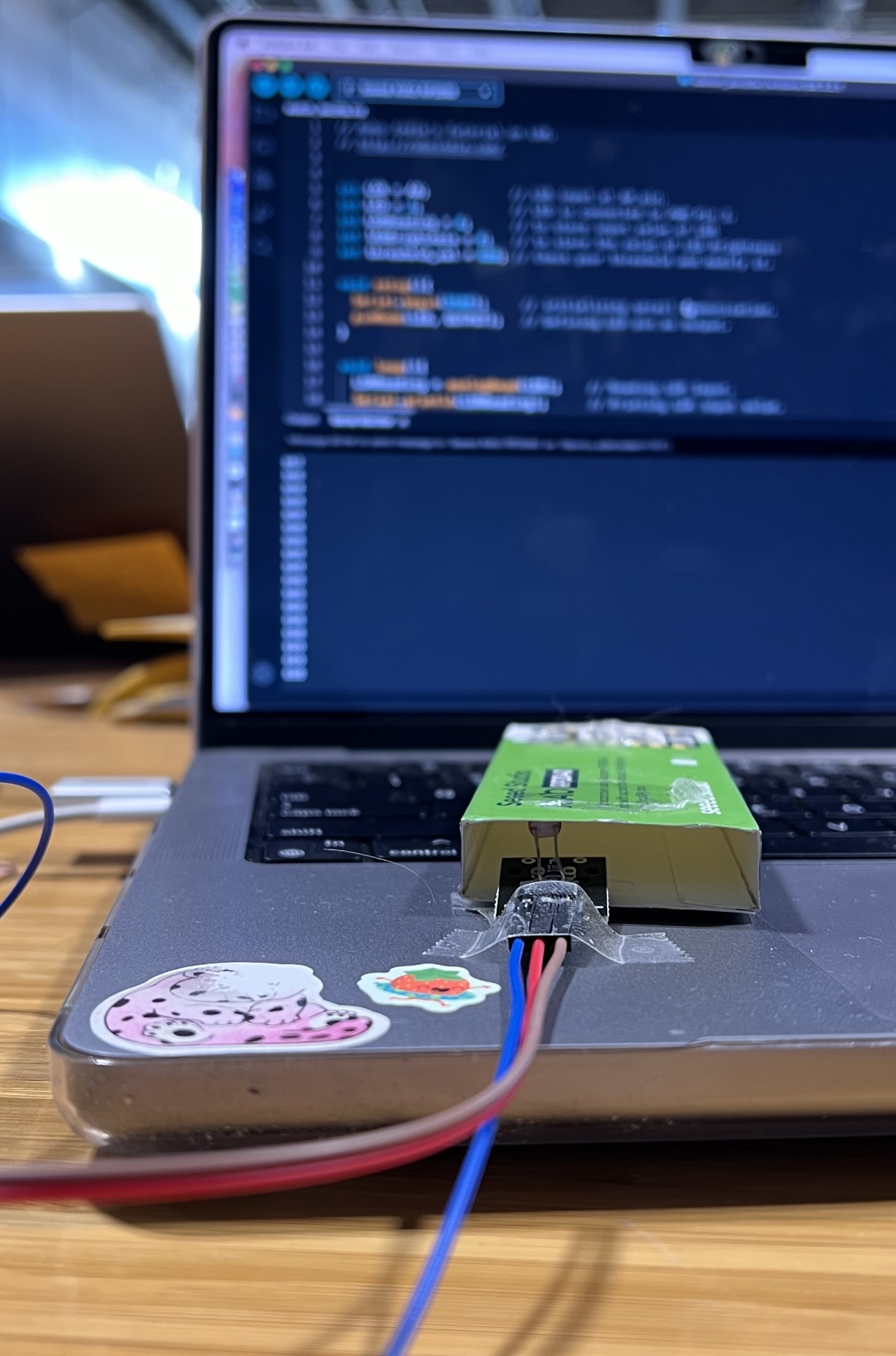
Coding The Input
The sensor I am using this week is the HC-SR04 ultrasonic sensor. This has the ability to detect the distance between itself and an object. I will use this to generate an input that my computer reads. The HC-SR04 has 4 pinouts; the VCC, Trig, Echo, and GND. The VCC connects to the 5V pinout of my microcontroller - provides power. GND is connected to ground to create the electrical circuit loop. The Trig and Echo pins connect to any digital pin on my microcontroller. Trig pin receives the control signal from Arduino (pulse), and Echo sends a signel (pulse) to Arduino. Arduino then measures the duration of pulse to calculate distance.
After connecting my sensor to my microcontroller PCB, I opened Arduino IDE. With the help of "How to Mechatronics" webpage, Ultrasonic Sensor HC-SR04 and Arduino - Complete Guide, I was able to follow along and code my input device to produce readings. Below you will find the code I used to program my sensor to give me a distance reading.
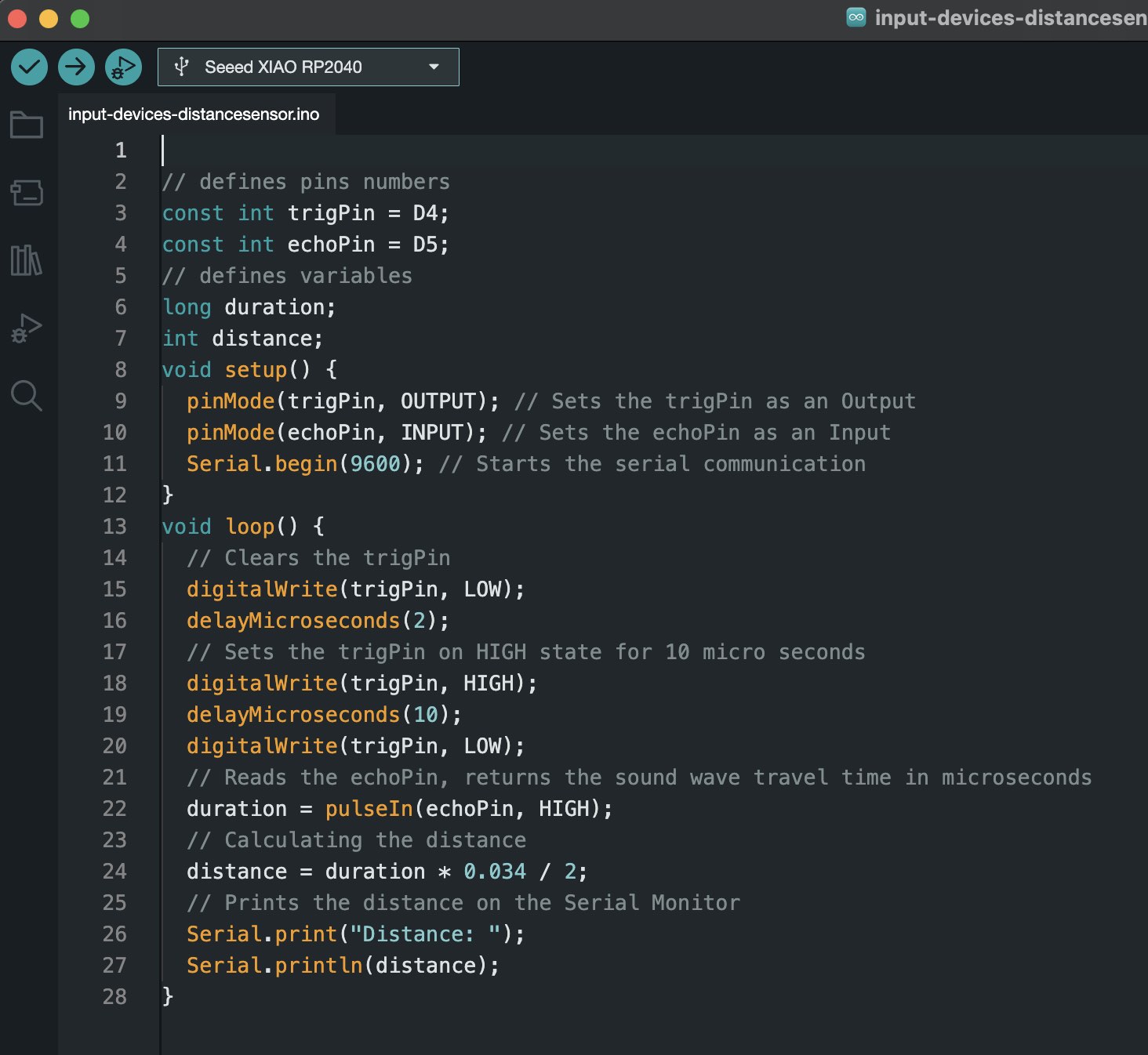
Code Breakdown
"const int" defines the pins from the XIAO RP2040 as Trig or Echo for the HC-SR04. This will allow the coded information to get across and accurately pulse the signal out and receive it to measure distance.
"long" and "int" defines variables before the code is received.
"void setup" is where you can set the pin modes as input or output. It is also where you do any setup recquired at the beginning of the program.
"void loop" is where the majority of your active code will be. I use it to send out my cycle of signals, set the duration calculation, etc.