Click Here to go to Andy's Page
Click Here to go to Kelleigh's Page
Week 3. Computer Controlled Cutting
Group Assignment
Laser Cutting Tutorial
You need these programs:

Using the Laser Cutter:
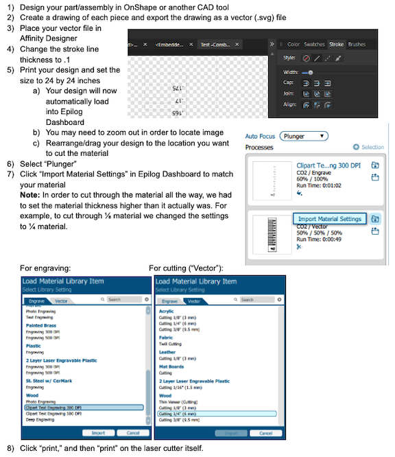
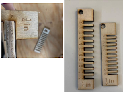
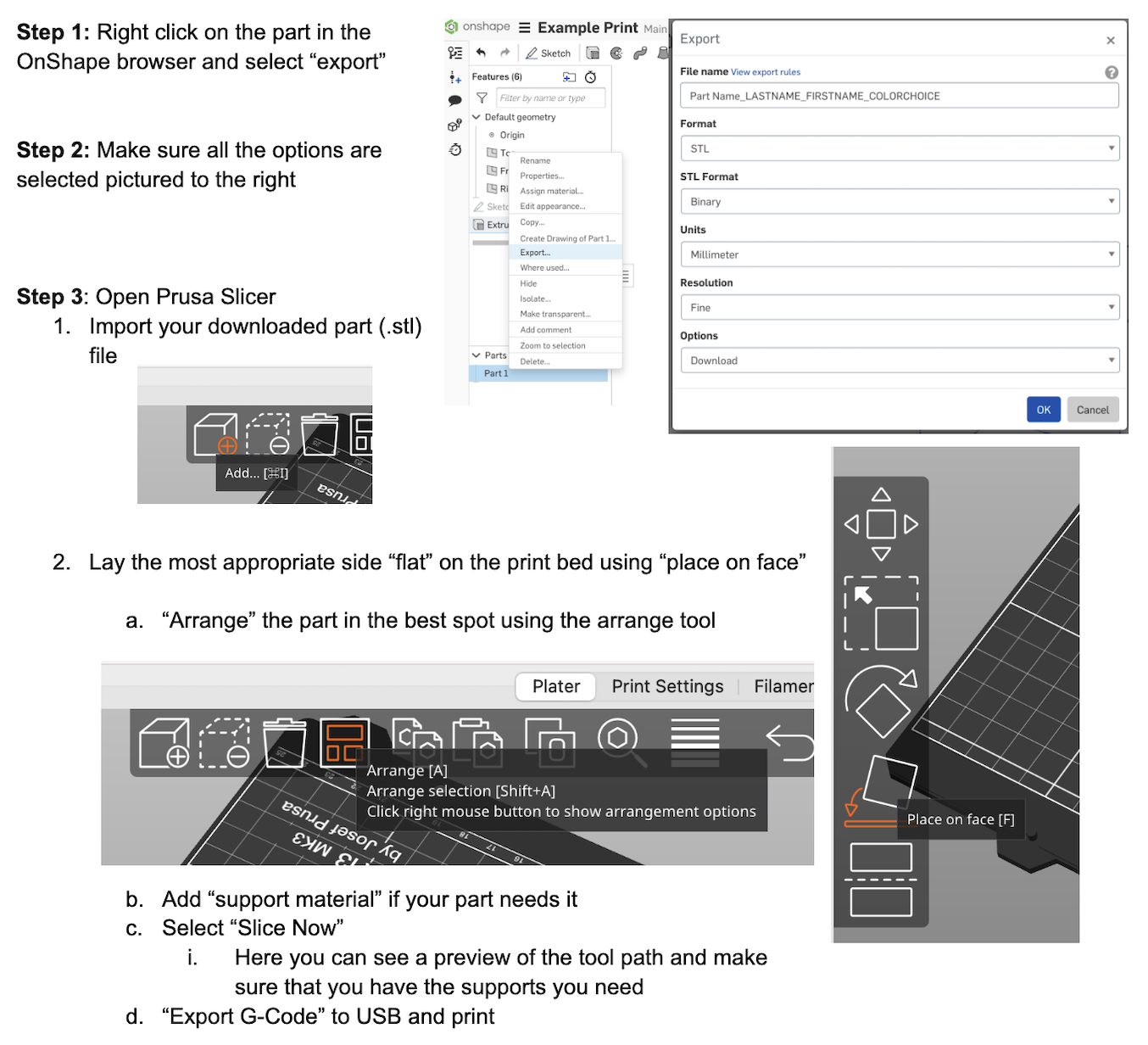
In order to determine the proper design dimensions for a good “press fit” accounting for the kerf (the laser burns away a portion of material when it cuts through) we used the following designs to find the proper fitting depending on the thickness of the material.
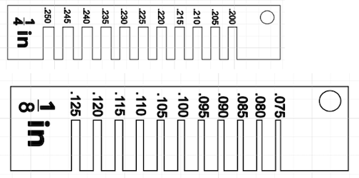
Example: While the material is ¼ (.25) inches thick, a slot that is .25 leaves too much wiggle room for a proper fit.
Vinyl Cutting Tutorial
You need these programs:

Getting Started/Design:
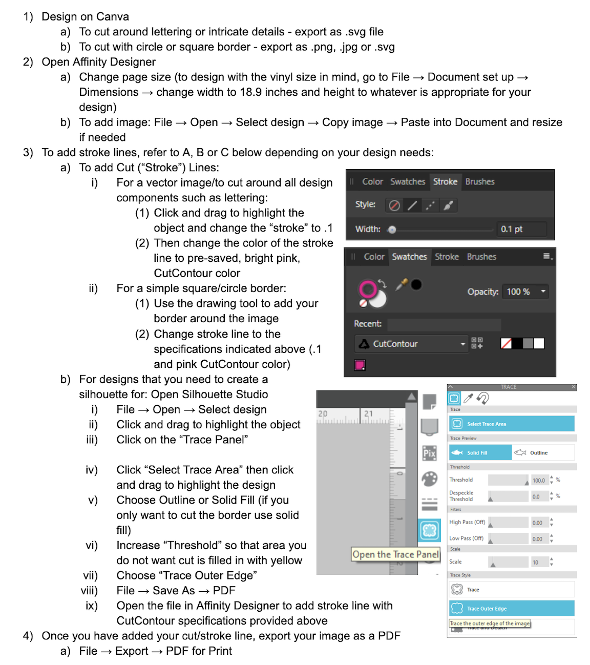
Using the Vinyl Cutter:
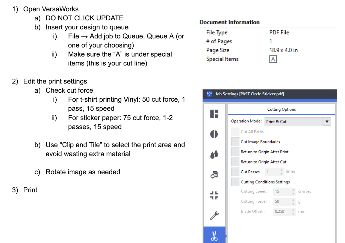
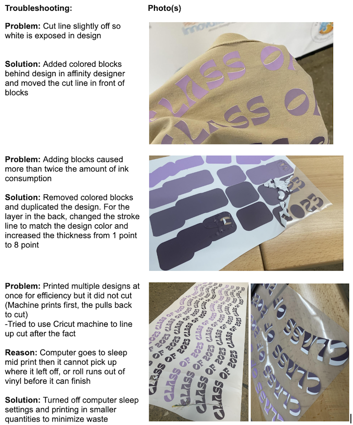
Project: We have been helping the senior class design and press 133 sweatshirts using the vinyl cutter and heat transfer press. Through this process, we have run into many issues that required trouble shooting and have been able to determine the best settings to use for various materials and designs.
Here are photos of the finished design:

Here are photos of some of the problems we have experienced and the solutions:

Week 4. Embedded Programming
This week we...
Group Assignment
Insert assignment description...
Heading...
Info and photos...
Week 5. 3D Scanning and printing
This week we optimized the settings for our 3D printers.
Group Assignment
Test the design rules for your 3D printer(s. Document your work on the group work page and reflect on your individual page what you learned about characteristics of your printer(s)
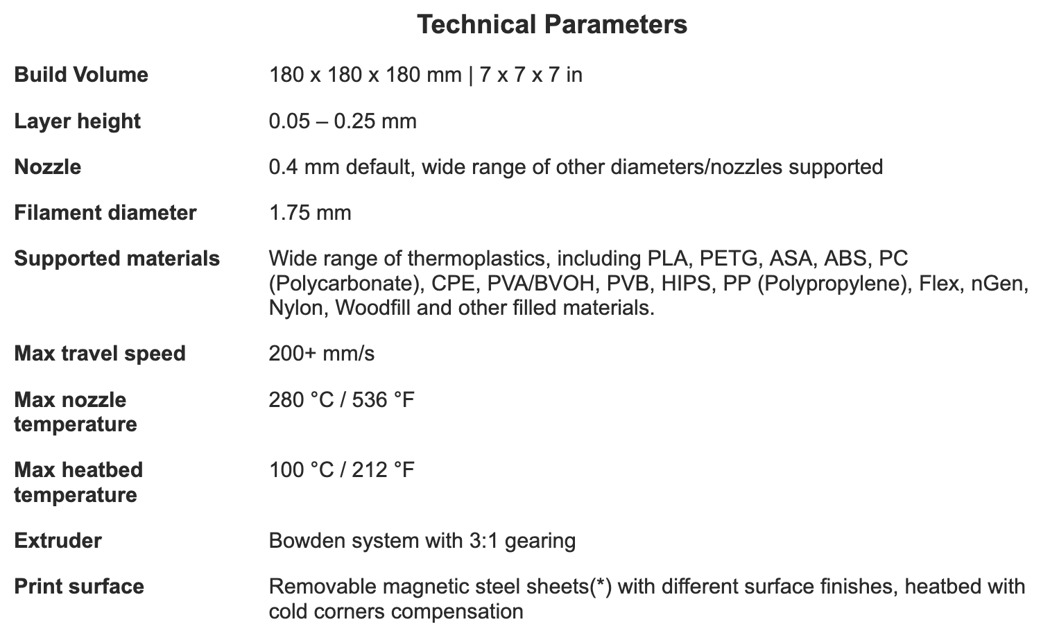
Prusa Mini Design Parameters
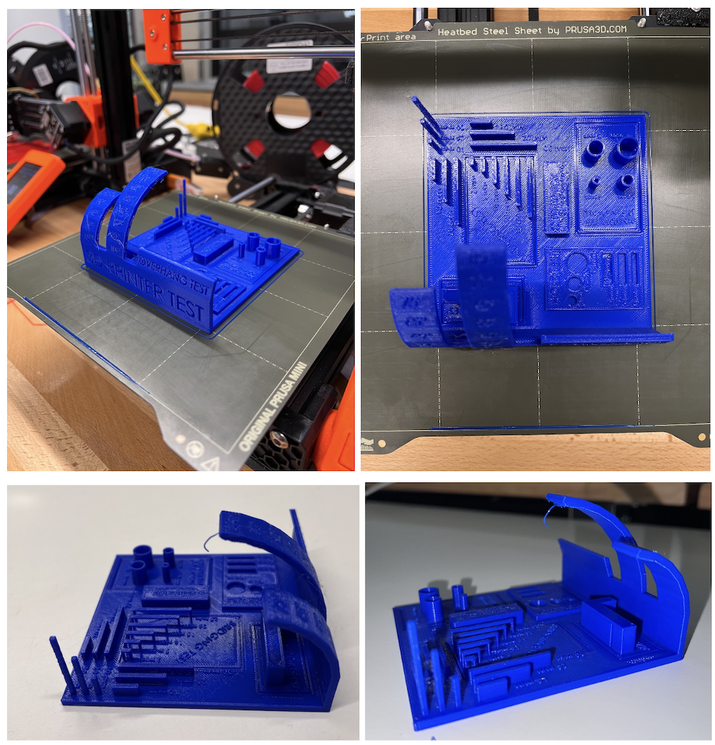
Test Print
You need these programs:
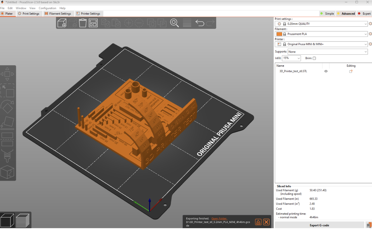
Preparing Your Print / Using Prusa Slicer
You need these programs:
Using the 3D Scanner:
You need these programs:
Getting Started:
Our current scanners are not the appropriate size for the iPad models that we have so we are awaiting a new scanner.
Week 6. Electronics Design
Week 7. Computer controlled machining
Week 8. Electronics production
Week 9. Output Devices
This week, we discussed output devices. An output device is any component which converts information from the microcontroller to a perceivable form by humans.
The group assignment is to: "measure the power consumption of an output device."
Power
First, what is Power?
The power in an electrical circuit is a measure of how much work can be done in a certain amount of time. This can be measured with a multimeter. The formula for power is P=I*V . Power (P) is measured in watts, voltage (V) is measured in volts, and current (I) is measured in amps.
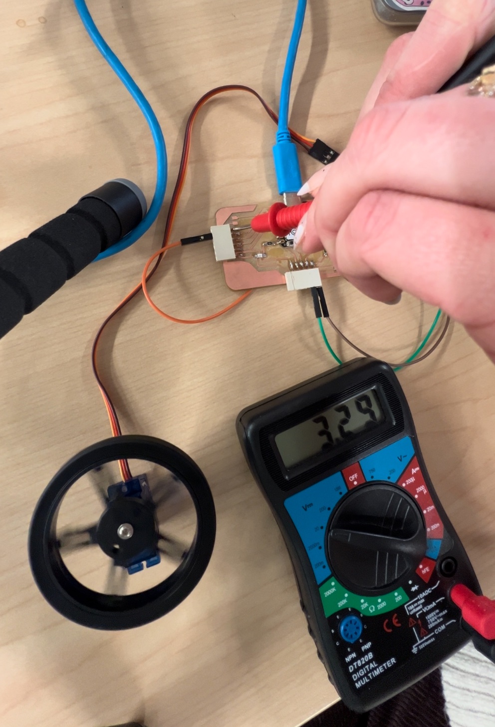
We used a multimeter to test the power consumption of our output device, the servo motor. To do this, we touched the black wire of the multimeter (ground) to the ground pin of the board, and touched the red wire probe to the pin with the servo attached. Our reading was pretty consistent around 3.29 V.
After measuring voltage, we realized that for this assignment, we needed to measure current (amps).
Voltage vs Current
Current and voltage are not the same. Voltage is the potential, current is the actual flow, so to measure current, you essentially have to break the circuit.
Voltage
- Voltage: Voltage is the measure of electric potential energy per unit charge. It is the electrical force that drives electric current between two points.
- Unit: Voltage is measured in volts (V).
- Symbol: It is represented by the symbol "V".
- Effect on the Circuit: Voltage is the force that drives current through a circuit. It is the cause, and it can exist without current.
- Measuring Instrument: Voltage is measured using a voltmeter, which is connected in parallel to the component where the voltage drop is to be measured.
Current
- Current: Current is the rate at which electric charge flows through a circuit. It is the actual flow of electrons.
- Unit: Current is measured in amperes (A).
- Symbol: It is represented by the symbol "I".
- Effect on the Circuit: Current is the flow of electric charge, and it is dependent on the circuit's resistance. It is the effect, and it cannot flow without voltage.
- Measuring Instrument: Current is measured using an ammeter, which is connected in series with the component being measured.
In summary, current is the flow of electric charge, measured in amperes using an ammeter, and it is the effect that cannot flow without voltage. Voltage is the electrical force driving the current, measured in volts using a voltmeter, and it is the cause that can exist without current.
Helpful Sites
Video: How to measure current of servo Multimeter BasicsStep 1: Reconfigure multimeter
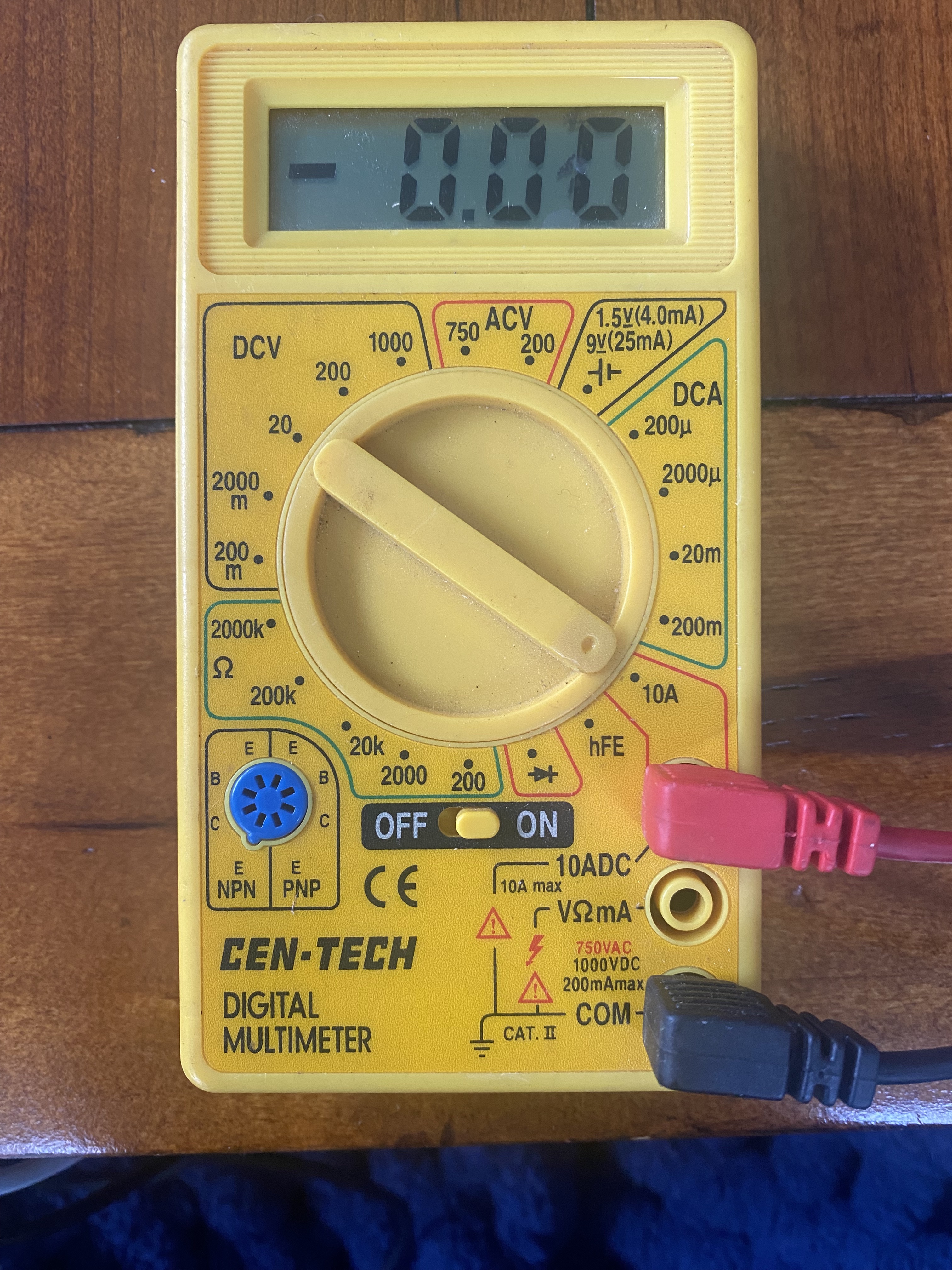
First, you need to configure the multimeter to read current. Measuring current with a multimeter is a bit trickier than measuring voltage or resistance. First, you need to set the multimeter to the current function and choose AC or DC. Then, put the red probe in the 'A' jack and the black probe in the 'COM' jack. Finally, place the probes in the circuit where you want to measure the current. This will help you find out how much current is flowing through the circuit. You can also watch this video for a visual guide: How to Measure Current with a Multimeter
Here is an image that shows how the multimeter should be set up to read current:
Step 2: Reading the current:
To measure the current in a servo motor, you would typically need to use a current sensor or a multimeter. The specific placement of the probes or sensor can depend on the setup of the servo motor and the availability of access points for measurement. However, in general, the most common way to measure the current in a circuit is by placing the current sensor or the multimeter in series with the load (in this case, the servo motor). This means interrupting the flow of current from the positive terminal of the power supply to the positive connection of the load, and then from the negative connection of the load to the negative terminal of the power supply. The current sensor or the multimeter is then placed in this interruption to measure the current flowing through the circuit. It's important to ensure that the current sensor or multimeter is set to an appropriate range for the expected current draw of the servo motor.
In summary, to measure the current in a circuit, you should place the red probe of the multimeter on the positive side of the circuit and the black probe on the negative side. When measuring the current in a servo motor, you would place the probes in series with the circuit, ensuring that the current flows through the multimeter.
Ran into trouble...
Servo motor stopped working or “pulses” rather than running consistently. See video:
According to reserach... the reason for this may be...
...The servo motor may stop when measuring the current due to the multimeter's internal resistance affecting the circuit. The lower current-measuring range of the multimeter can introduce too much series resistance, causing the servo to drop the supply voltage when it tries to draw current. This can lead to unexpected behavior, including the servo stopping. Additionally, the fast spikes in current draw by the servo motor may not be accurately captured by the multimeter. It's important to use the appropriate current-measuring range and consider the impact of the multimeter's resistance on the circuit when measuring the current drawn by the servo motor
...Measuring the current in a servo motor can impact its performance due to the dynamic nature of the current draw. When a servo motor is in operation, the current it draws can vary based on factors such as the load and its movement. The current may have a pulse waveform, with the duration of the pulse changing based on the motor's activity. Additionally, the current draw may not be constant, as it can drop to almost zero when the servo reaches its desired position and then increase when it is pushed out of position. Therefore, when measuring the current draw of a servo motor, it's important to consider the dynamic nature of the current and its impact on the motor's overall performance
After revisiting the project and trying it all again we were able to power the servo with a 9V battery and successfully measure current as seen in the video below.
We got a reading of about 2.7 mA when measuring current through the servo motor.
Week 10. CNC Machine Design
This week we brainstormed, designed, and programmed a CNC pen plotter.
Week 11. Input Devices
Week 12. Molding and Casting
Group Assignment
Review the safety data sheets for each of your molding and casting materials, then make and compare test casts with each of them
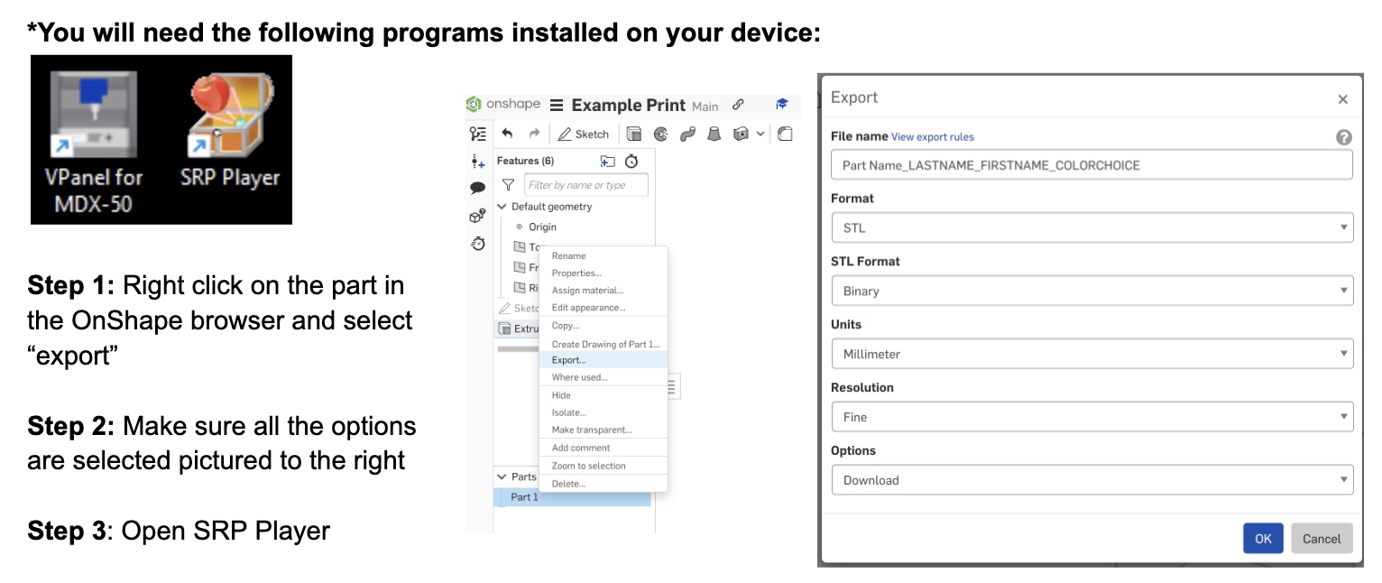
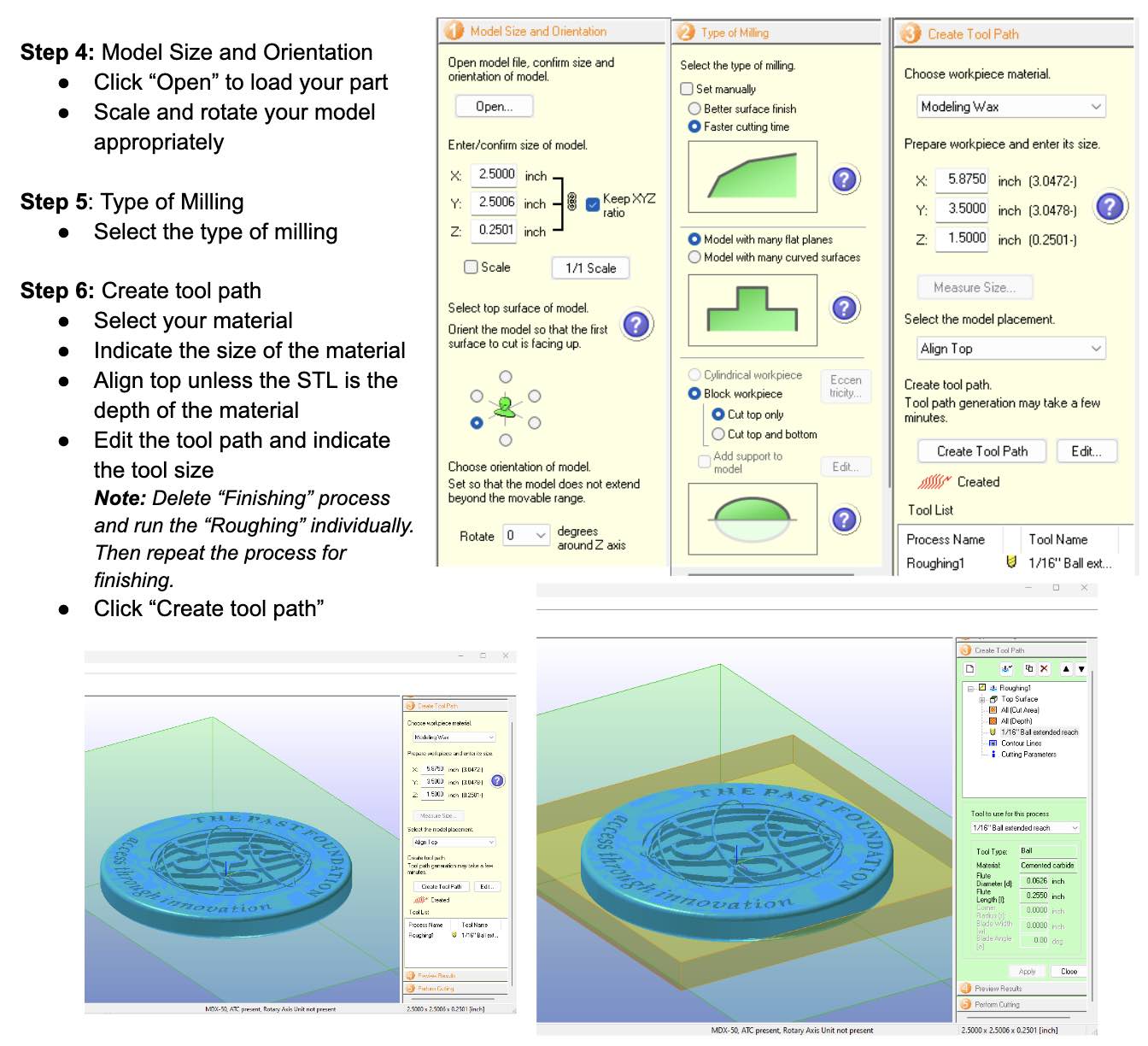
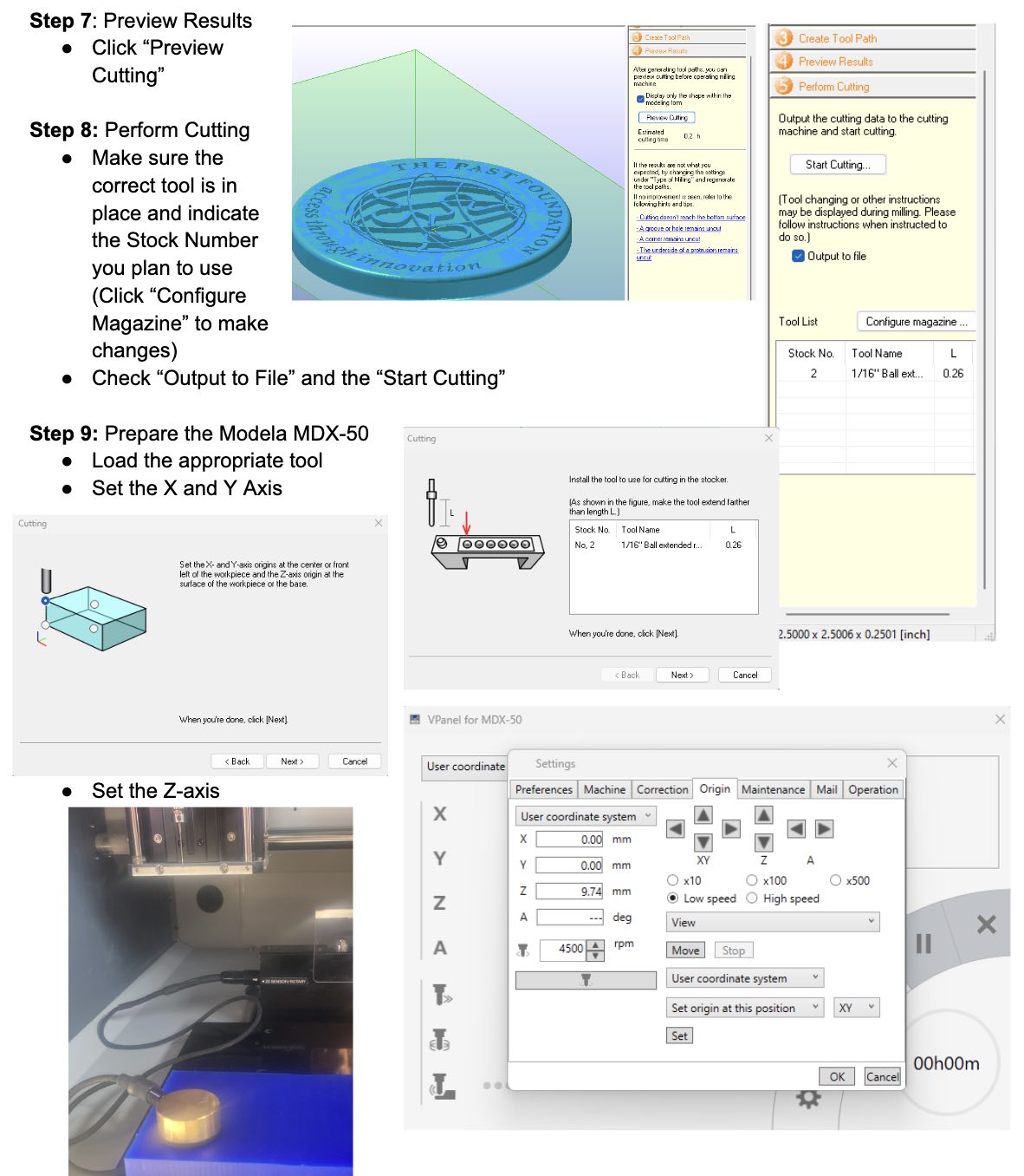
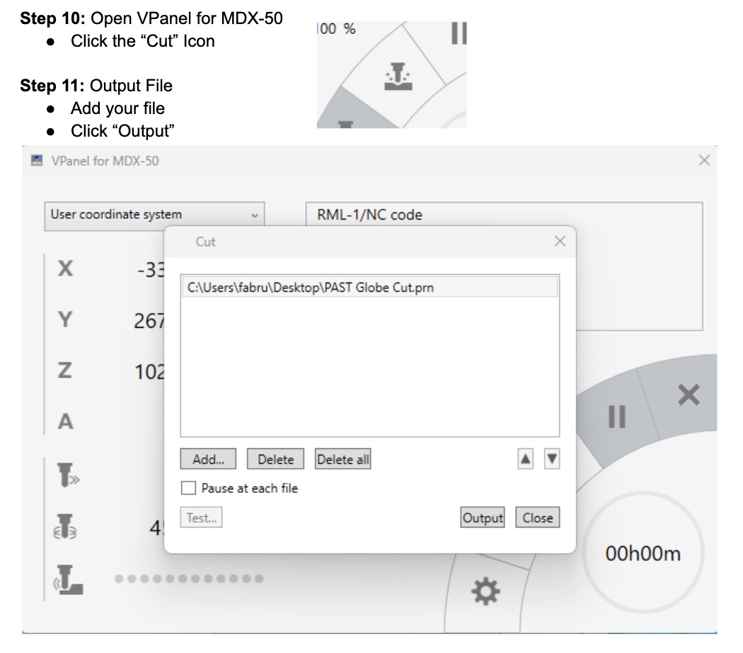
Instructions for Making a Mold Using the Model MDX-50
Trying Different Materials
Below are some photos that show the results of our testing different materials. The first photo is using food grade silicone, so that we could use them with melted chocolate. The second is Oomoo Silicone Rubber.


