My Final Project: The Green Guardian
Presentation
Slide:
You can view my presentation here:
Video Presentation:
In Use:
My Final Project (Documentation)
This is where I will start defining my final project.
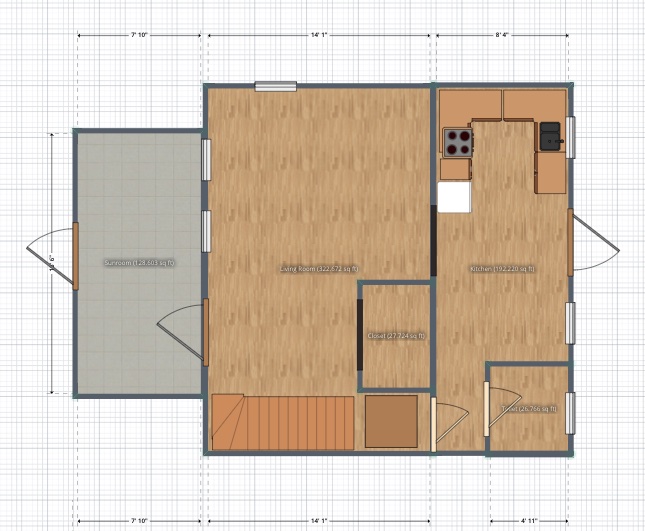
I have decided to create an interative model of a home that I am renovating. I will use this to plan for material purchases including square footage for flooring, tiling, countertops, drywall, paint coverage, baseboards and window trim lengths, location and sizing of appliances and furniture, and the location of electrical outlets and can lights etc.
Intial Planning and 2D Design
I first used a website called Planner 5D to start mapping out the floor plan before creating the CAD model.
3D Modeling
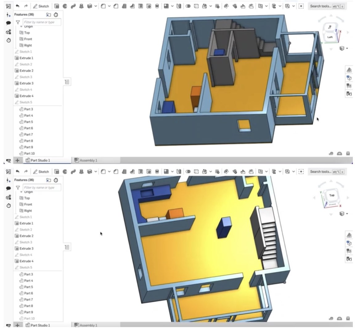
I then used OnShape and created a 3D model of a section of the house using my 2D plan as a guide. Here are some photos of the model I made in OnShape:
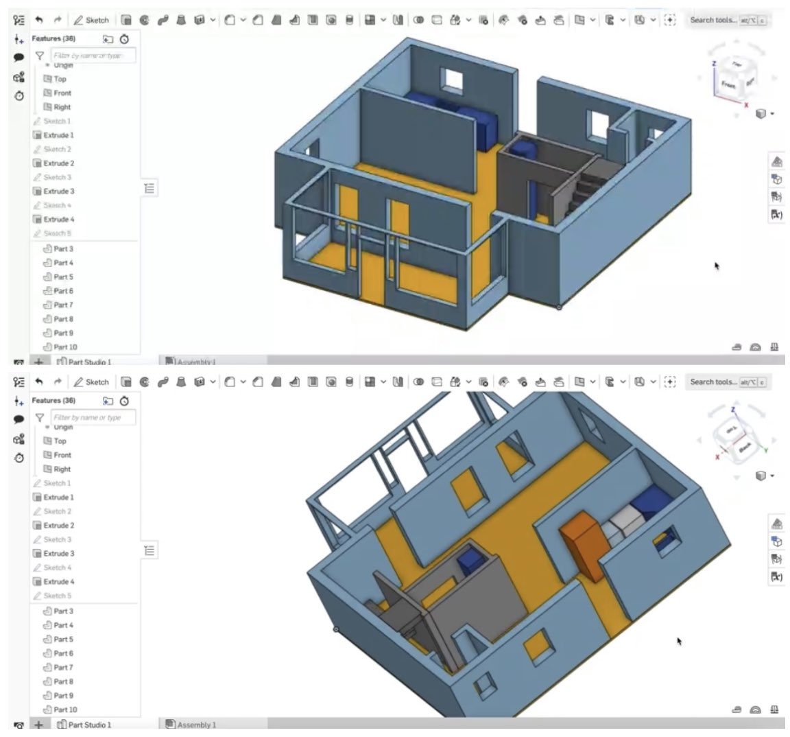
I chose to make some of the walls as separate parts because I am thinking about taking a wall/closet out.
Files
Here is the STL File of the model:
Change of Plans...
Intially, I wanted to create an interactive model of my house. While I have used many skills from this course during the home renovation process, including mapping a plan for laying floor and tile, making custom furniture etc, I have decided to create something that with more functionality and usability. Therefore, I have decided to make a plant moisture sensor that will alert me when it is time to water the plant so that hopefully, my plants stay healthier and live longer!
Week 18. Project Development
Project Overview
My project incorporates a diverse range of skills and processes that have been practiced throughout this course. The aforementioned components are outlined below:
- 2D and 3D Design: 2D Design: In the project, 2D design is involved in creating the layout and schematics for the electronic circuit. This includes designing the traces, connections, and components on the PCB using computer-aided design (CAD) software. 3D Design: The housing and enclosure for the moisture sensor, LEDs, and electronics are designed in 3D. This includes creating a 3D model of the components using CAD software. The 3D design ensures that the physical components fit together seamlessly.
- Additive and Subtractive Fabrication Processes: Additive Fabrication: The 3D printing of the housing and enclosure is an additive process. Layer by layer, the 3D printer adds material to build up the desired structures. Subtractive Fabrication: The milling of the custom PCB involves a subtractive process. Material is removed from a blank PCB to create the circuit traces and pads using a milling machine.
- Electronics Design and Production: Design: The electronic circuit for interfacing the moisture sensor, LEDs, and Seeed Studio board is designed using CAD software. This involves creating the circuit layout, specifying components, and designing the connections. Production: The designed circuit is translated into a physical form through the production of a custom PCB. The milling process creates the necessary circuit traces and features on a blank PCB.
- Embedded Microcontroller Interfacing and Programming: Interfacing: The Seeed Studio development board interfaces with the electronic circuit and the various components, including the moisture sensor and LEDs. Programming: The microcontroller on the Seeed Studio board is programmed to read data from the moisture sensor, interpret it, and control the activation of the LEDs based on the moisture levels.
- System Integration and Packaging: Integration: All individual components, including the 3D-printed housing, custom milled PCB, moisture sensor, LEDs, and Seeed Studio board, are integrated into a cohesive system. Packaging: The 3D-printed housing serves as the packaging for the system. It encapsulates and protects the electronic components while providing easy access for maintenance.
In summary, the project demonstrates a comprehensive integration of 2D and 3D design, additive and subtractive fabrication processes, electronics design and production, embedded microcontroller interfacing and programming, as well as system integration and packaging. Each element contributes to the functionality and aesthetic of the Smart Plant Moisture Monitoring System.
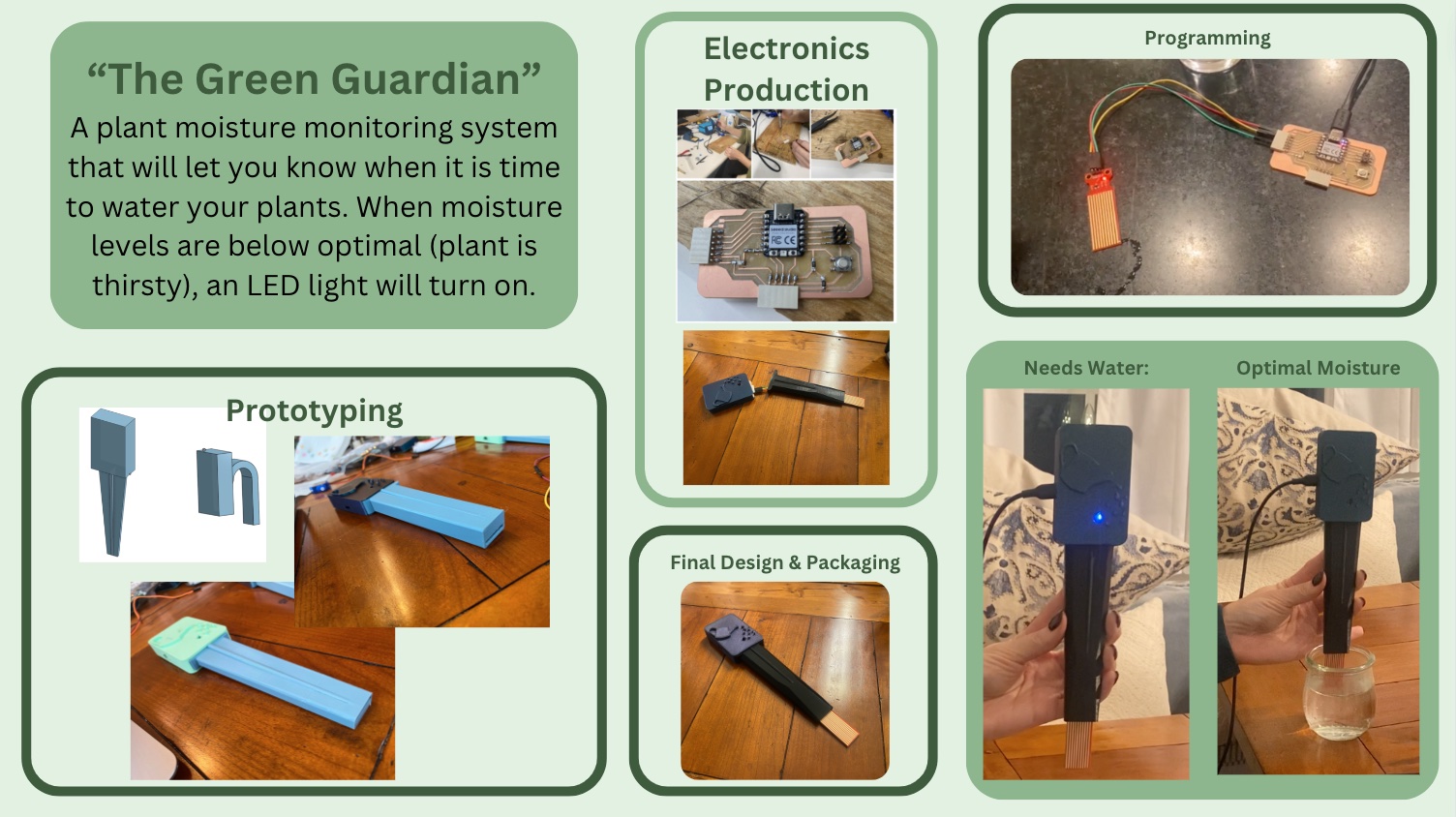
Project Proposal: “The Green Guardian”
What will it do?
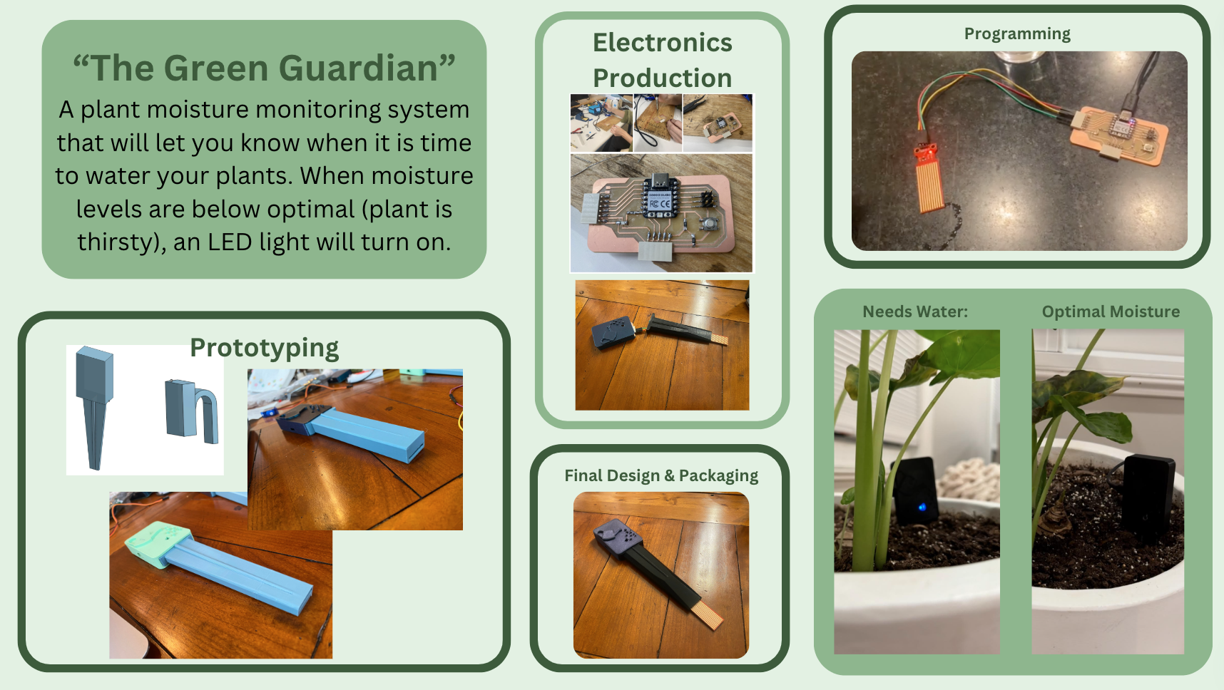
The proposed project is a Smart Plant Moisture Monitoring System that continuously monitors the soil moisture level and provides real-time feedback. The system will employ a moisture sensor to measure soil moisture content. The data collected will be processed by a Seeed Studio board, and the results will be indicated using red, yellow and green LEDs. The subtractive process will involve milling a custom PCB for the electronic circuit.
In the proposed system, the red, yellow, and green LEDs will serve as visual indicators to convey the soil moisture status. Here's how the LEDs will function based on the moisture readings:
- Green LED (Appropriate Moisture): When the soil moisture level is within the optimal range for the plant, the system will illuminate the green LED. This indicates that the soil has sufficient moisture, and the plant is in a healthy state.
- Yellow LED (Watering Suggested): When the moisture level drops below the optimal range, but is not critically low, the yellow LED will be activated. This suggests that the plant could benefit from additional watering, prompting the user to take action.
- Red LED (Immediate Attention Needed): If the soil moisture level is critically low and potentially harmful to the plant, the red LED will be lit. This signals that immediate attention is required, prompting the user to water the plant urgently.
By utilizing these color-coded LEDs, the system provides clear and intuitive feedback to the user about the moisture status of the soil. This visual representation allows for quick and easy assessment, even without having to check specific moisture readings. It enhances the user experience by translating complex data into a simple and actionable visual display.
Who's done what beforehand?
Similar projects focusing on soil moisture monitoring without automated watering systems have been undertaken by hobbyists and researchers in the domain of precision agriculture. However, this project's uniqueness lies in the integration of 2D and 3D design, the use of a Seeed Studio board, and the emphasis on milling a custom PCB.
What will you design?
The project will involve designing a housing for the moisture sensor, LEDs, and electronics using 3D design software. This housing will be modular and designed for easy assembly and disassembly. Additionally, the electronic circuit will be designed using CAD software, and a custom PCB will be milled for the project.
What materials and components will be used?
- Moisture sensor
- Red and green LEDs
- Seeed Studio development board
- Custom milled PCB
- 3D printing filament
- Enclosure for the electronics
- Power supply components
Where will they come from?
The components can be sourced from electronics suppliers such as Seeed Studio, Amazon, or local electronics stores. The 3D printing filament and milling tools can be obtained from various online suppliers.
How much will they cost?
Costs will vary based on the specific components chosen and the supplier. A rough estimate would be in the range of $30 to $50, depending on the quality and features of the selected components.
What parts and systems will be made?
3D-printed housing for the moisture sensor, LEDs, and electronics. Custom milled PCB for the electronic circuit. Enclosure for housing the electronic components. Electronic circuit for interfacing the moisture sensor, LEDs, and Seeed Studio board.
What processes will be used?
- 2D and 3D design: Using CAD software for designing the housing, enclosure, and electronic circuit. Additive fabrication processes: 3D printing of the designed components. Subtractive fabrication processes: Milling a custom PCB for the electronic circuit. Electronics design and production: Designing the electronic circuit and assembling the components.
- Embedded microcontroller interfacing and programming: Programming the Seeed Studio board to read sensor data and control LEDs.
- System integration and packaging: Assembling all components into the 3D-printed housing and enclosure.
What questions need to be answered?
Some of the questions I will need to answer include:
- What is the optimal placement of the moisture sensor for accurate readings?
- How far does it need to penetrate the soil?
- How will the system handle variations in soil types and conditions?
- How will the programming need to vary depending on the plant species and time of year?
- What programming logic will be used to interpret and display moisture levels?
- What is the appropriate moisture level?
- How will the system be powered and for how long can it operate on a single charge?
By addressing these aspects, the project will showcase mastery of 2D and 3D design, additive and subtractive fabrication processes, electronics design, embedded programming, and system integration, with the added benefit of my plants living longer!
Project Plan
In order to complete my project over the course of 10 weeks, I have developed a project plan:
In order to complete my project over the course of 10 weeks, I have developed a project plan:
Week 1: Project Kickoff (Sep 21 - Sep 27):
- Familiarize myself with project requirements.
- Confirm the availability of tools and resources.
- Set up the project workspace.
Week 2: Initial Planning (Sep 28 - Oct 2):
- Define project scope and objectives.
- Begin creating a rough project plan.
- Research and Resource Identification (Oct 3 - Oct 4):
- Research required technologies and resources.
- Identify suppliers for necessary components.
Week 3: Project Initiation and Planning (Oct 5 - Oct 9):
- Define project scope, objectives, and requirements.
- Create a detailed project plan outlining tasks, timelines, and resources.
- Component Identification and Ordering (Oct 10 - Oct 11):
- Identify and order necessary components.
Week 4: PCB Design (Oct 12 - Oct 15):
- Begin the 2D design of the electronic circuit.
- Simulate and review the design for any potential issues.
- Finalize 2D Design (Oct 16 - Oct 18):
- Complete and finalize the 2D design of the electronic circuit.
Week 5: PCB Milling Preparation (Oct 19 - Oct 22):
- Research and select appropriate CNC router bits for PCB milling.
- Test the CNC router with scrap material to ensure proper functionality.
- Order additional bits if necessary.
- Material Ordering (Oct 23 - Oct 25):
- Identify and order necessary components (moisture sensor, LEDs, Seeed Studio board, PCB materials, etc.).
Week 6: PCB Milling (Oct 26 - Oct 29):
- Mill the custom PCB using the finalized 2D design.
- Inspect and troubleshoot any issues with the milled PCB.
- Adjustments and Re-milling (Oct 30 - Nov 1):
- Make any necessary adjustments based on initial tests.
- Re-mill the PCB if required.
Week 7: Electronics Assembly (Nov 2 - Nov 5):
- Begin assembling the electronic components onto the milled PCB.
- Initial Testing (Nov 6 - Nov 8):
- Begin testing the functionality of the assembled electronic circuit.
Week 8: 3D Design and Printing (Nov 9 - Nov 12):
- Begin the 3D design of the housing and enclosure.
- Review and finalize the 3D design.
- 3D Printing (Nov 13 - Nov 15):
- Start 3D printing of the housing and enclosure.
Week 9: System Integration (Nov 16 - Nov 19):
- Integrate the electronic components into the 3D-printed housing.
- Ensure proper fit and alignment.
- Initial Testing (Nov 20 - Nov 22):
- Conduct preliminary tests of the fully integrated system.
- Identify any issues for resolution in Week 10.
Week 10: Testing, Optimization, and Finalization (Nov 23 - Nov 27):
- Conduct thorough testing of the complete system.
- Optimize any functionalities or design elements if needed.
- Address any issues discovered during testing.
- Documentation and Submission (Nov 28 - Nov 30):
- Finalize the project documentation.
- Prepare assembly and operation instructions.
- Submit the final project by November 30th.
Project Progress
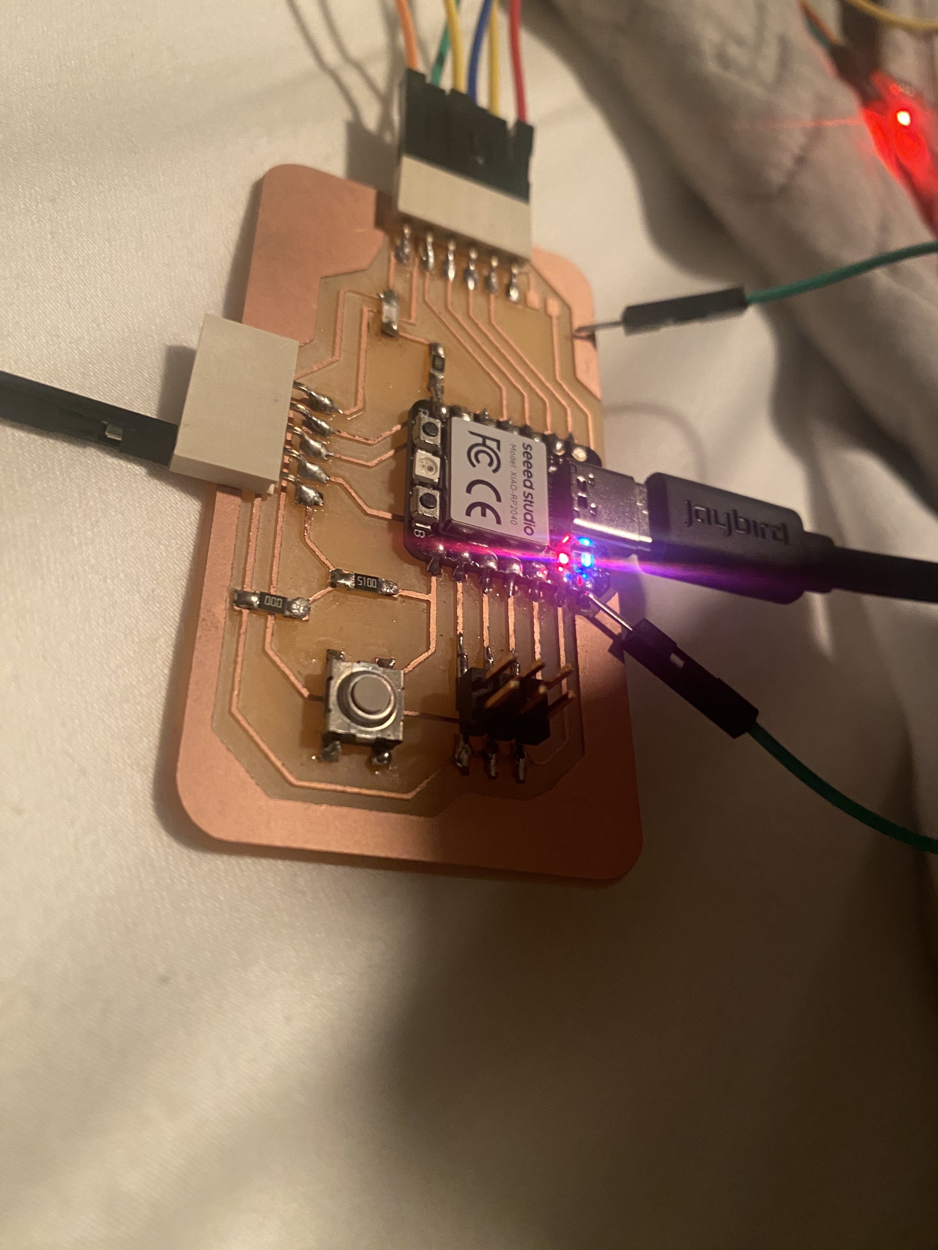
One issue I ran into was the pico board lost power and no matter what I did I could not get it to turn back on. After digging through many articles, I used a male to male wire as a little jumper cable and it final kickstarted it back up and running. See the image below.
In this version of code, I am using two LEDs. The green light shows up when the moisture level is optimal, and the red light comes on when the moisture levels are too low.:
After a lot of thought and keeping the final system integration and packaing in mind, I decided to use only one LED and have it integrated on my actual PCB. That way, there is less for the user to keep track of (multiple lights and colors meaning different things) so it streamlines the intended use and also simplifies the overall design making it more sleek and straightforward. In this new model, the light on means it needs attention (water), and the light off is good news, meaning the moisture level is optimal. I think this design will be more user-friendly, rather than a light being on all the time, which draws attention to it even when water levels are optimal, and the user is may get used to seeing it on all the time which will make it less obvious when it actual needs attention, and would also require the user to have to pay attention to the color of the light. Here is the new code and working model:
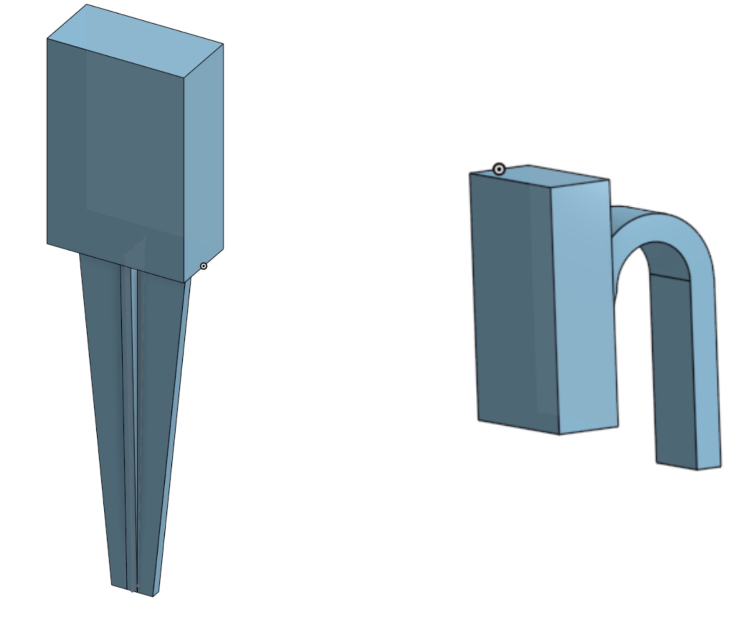
Packaging Design
Here are two rough ideas for the design:
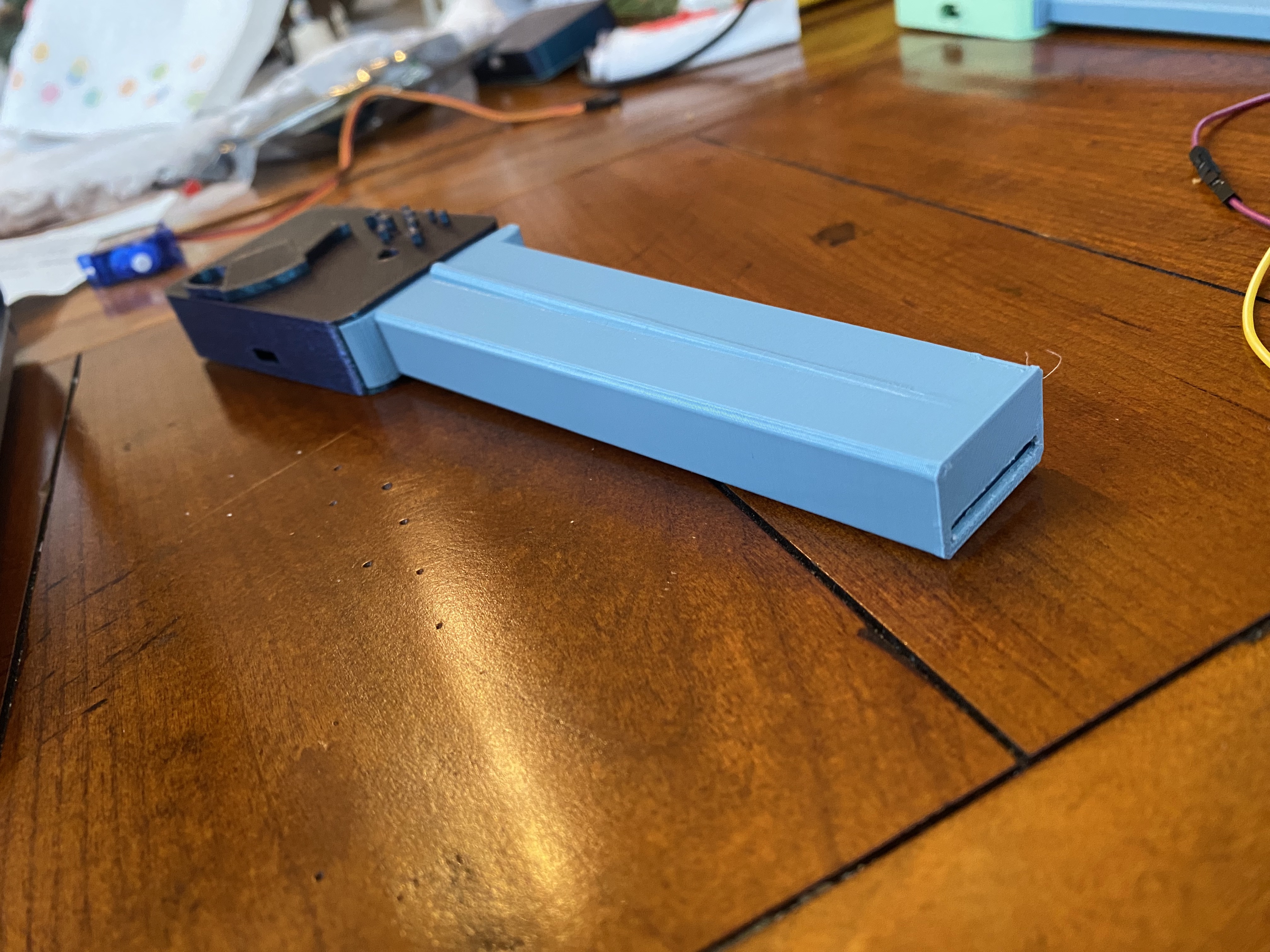
Here is the first prototype. The overall design was too thin to make room for the pins and wires that lead into the sensor.
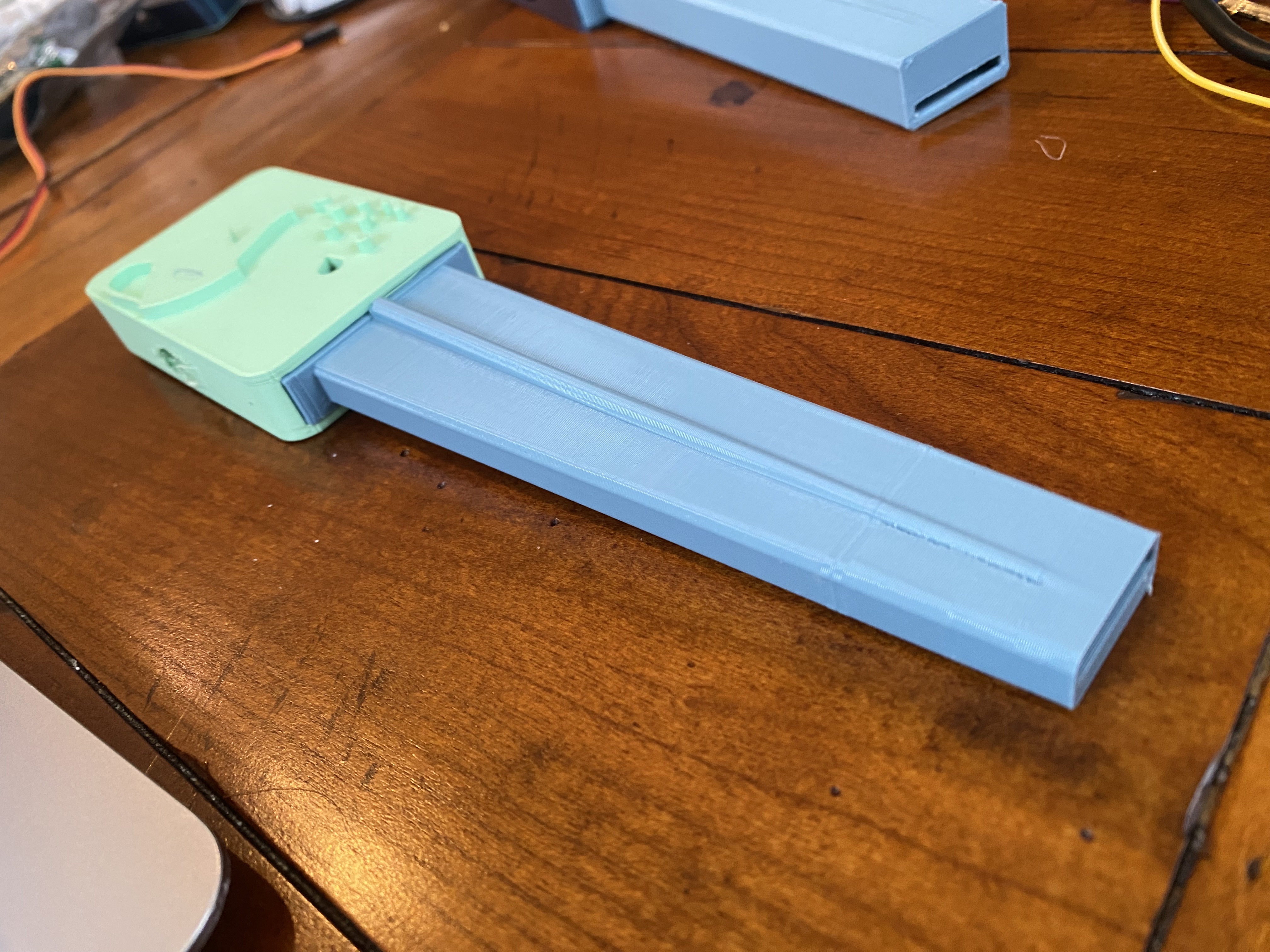
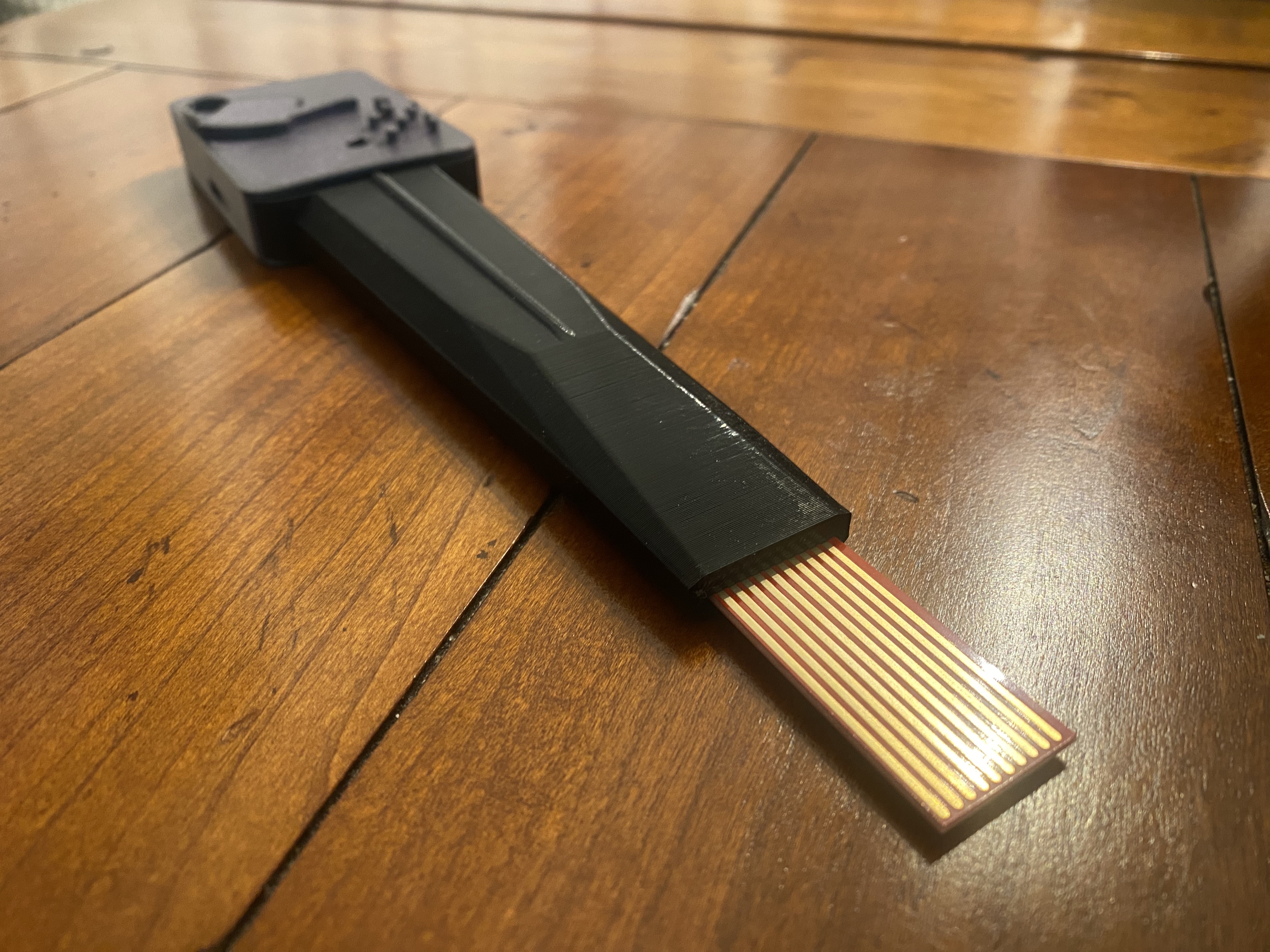
I modified the design to make room for the wires and I didn't like appearance of it. It seems too thick and has too much wiggle room for everything to stay snug inside. Also, I don't like the bottom as the flat portion will be difficult when sliding into the plant soil.
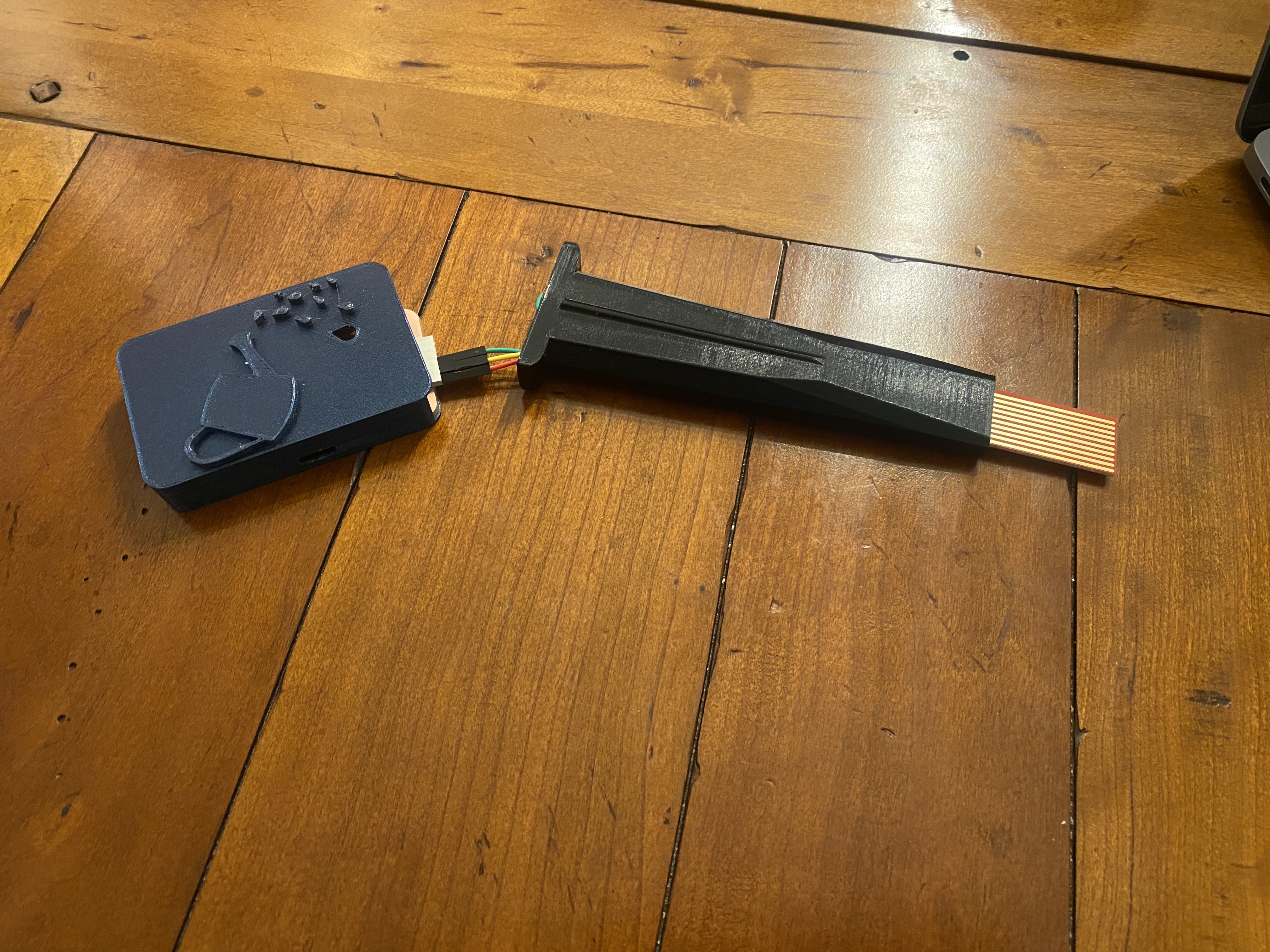
I then modified the bottom piece to make it as thin as it can be while still allowing the sensor to clear through the bottom part and made it on an angle and used chamfers so it can slide into the soil more easily:
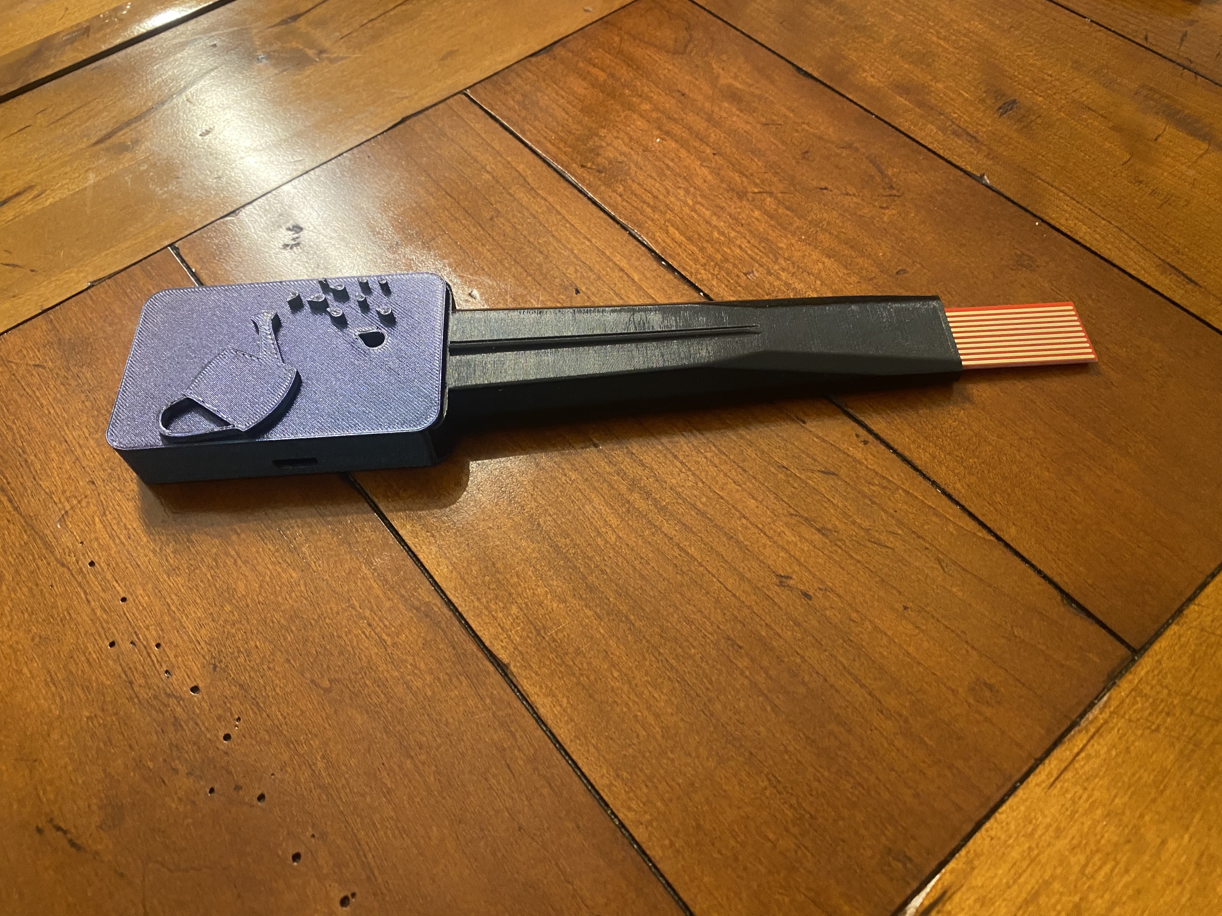
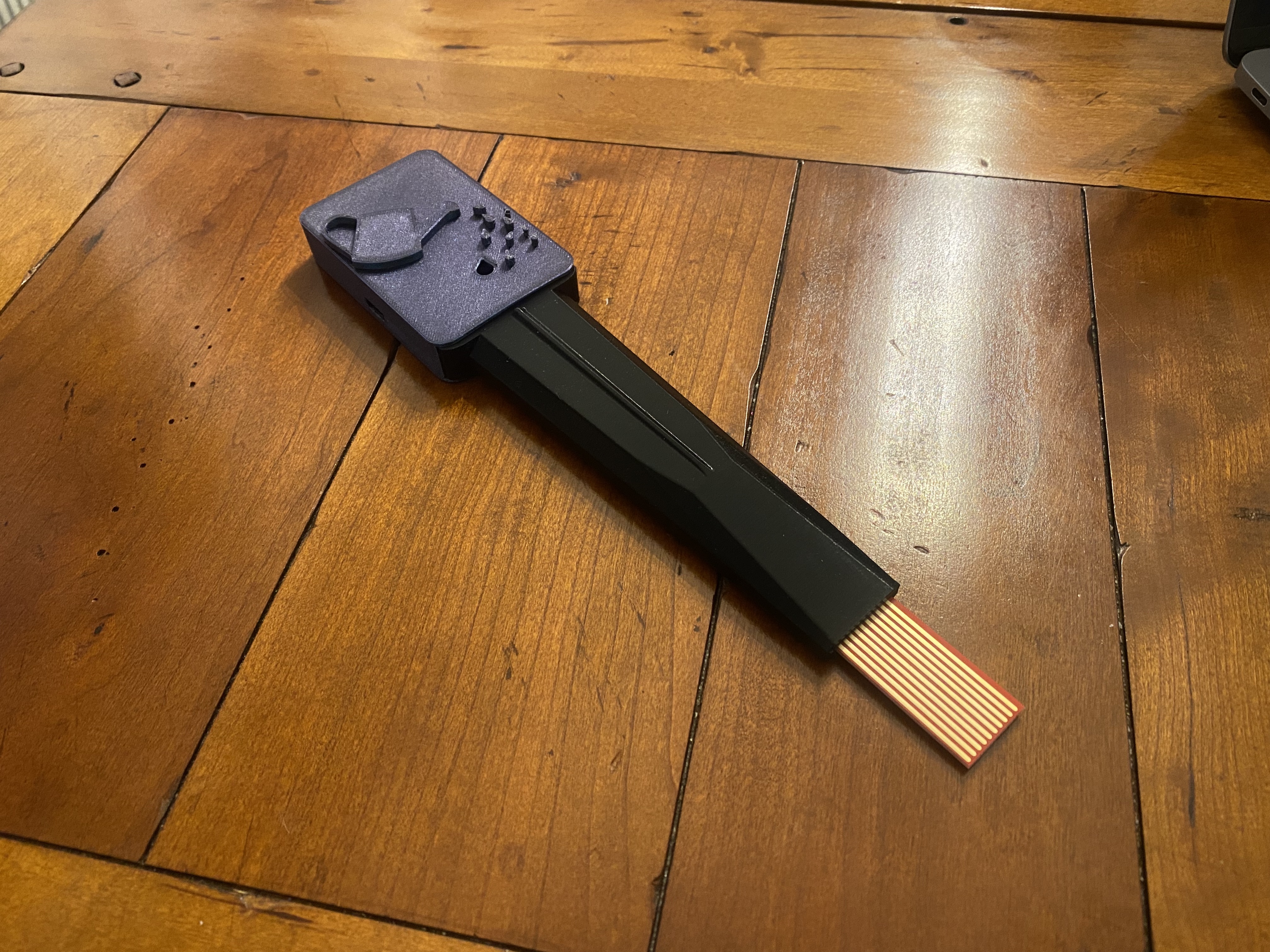
Here is the working design in the package.
Here are the STL Files for my final design:
Important Note:
It has been brought to my attention that the subtractive process of milling the PCB board is not sufficient for final project requirements. I decided to add a small "window" using the laser cutter that fits perfectly into the slot for the LED to shine through. I think this enhances the overall packaging and design.
Intended Use:
Presentation
Slide:
You can view my presentation here: