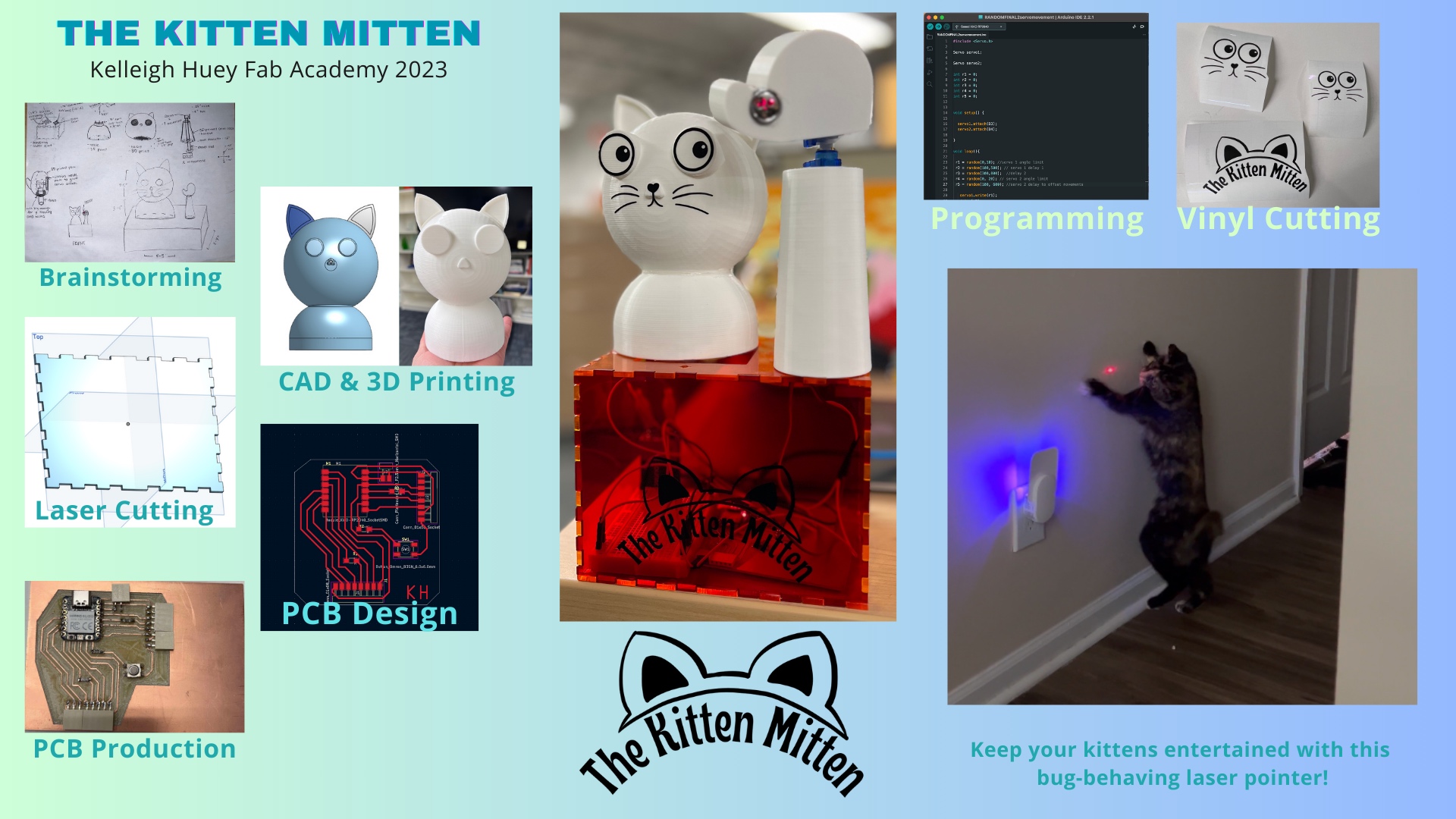
My Final Project
The Kitten Mitten - Final Slide and Video
Featured again and further discussed later on this page.
Slide by Kelleigh Huey made in Canva.
Video by Kelleigh Huey made in Biteable.
The information on this page will be a progression of how I completed my final project. I begin with an idea of a smart-plant pot, which would tell the user when their specific plant needs watered. After scrapping idea #1, and adopting two kitties, I found another idea I liked better - a desk toy that I could have while I work, but would also act as a cat toy, moving two servos attached to a laser to keep my cats distracted while I work.
Follow along my journey of how I made The Kitten Mitten - A Laser and Desk Toy
This is where I will start defining my final project idea and start to get use to the documentation process. I reimagined my final project several times, some of which are documented below. My final idea will be expanded upon below the first few sections of the page.
Brainstorming
I began thinking about what I wanted my final project to be and brainstorming possible ideas that I could use within my current job scope. I knew that I wanted to solve a problem or come up with a possible solution to something that I could then use in my summer programs with students.
My original idea, was a self-regulating plant pot that had sensors to test when the soil is too dry or too wet, sensors for conductivity that will aid the owner in calculating the overall nutrient concentration, and an LCD dislay. The dipslay would tell the owner what the stats are of the plant, and will have an animated face that corresponds to a color- red for your plant doing poorly, yellow for needs some attention, and green for all good.
October update: I am beginning my refresh of all of my final project documentation. I am keeping some of my original ideas and second version, etc. on here as a reminder that ideas change, inspiration changes, and life changes. I recently got 2 kittens and they absolutely love playing with the laser toy. (I always have one of their physical toys in my hands for when they really come close to "catching" "the laser dot (for satisfaction, they don't go crazy chasing lights all the time, etc.). This is generally a good idea if you do play with laser toys, and it is not recommended to have extensive playtime hours with laser toys. Also never ever shine it directly at them, at eye level, or similar. It can be very damaging to their eyes - just like it is your eyes.) Anyways, I remembered a project idea one of my students had over the summer, and wanted to take inspiration from that also.
Their original project was a laser turret on a servo, as a sort of "model" from some video game. I knew at the time I could use the idea to help my project but would need to add to it pretty significantly to 1.) make it my own, and 2.) hit the requirements of the final project.
Original Idea (since changed)
This was my original idea of a plant pot that could remind you when to water using soil and moisture sensors. I have decided to skip on this idea, because I am already capable of growing plants in a pot. What I have *not* been successful at is seed starting..
Idea #2- a Regulating Greenhouse for Seed Starting (also not my final idea - has changed)
The plant pot would be fun, but I think I want to scale it up a bit more. A bit of a backstory- last year I really wanted to start my garden from seeds so I went out and bought a small set of greenhouse equiptment. This was basically just plastic with separations that you fill with dirt and keep in the sun. I made the mistake of leaving it out on part of my deck, which got soaked every time it rained. We got a lot of rain last year. Basically, it didn't work, my seeds were drowning, and I had to buy established plants already. I want to avoid that now, so I plan to make a greenhouse out of acrylic, which includes a moisture sensor, a thermometer, and potentially a water nozzle to spritz when it gets too dry. If I cannot figure out the components of the water nozzle, I want to incorporate an LCD screen or LED lights that will alert the user when the moisture is too low, temperature is too high, or too low. I plan to also put LED lights within the greenhouse in the upper rim which will be programmable to change colors. Blue light stimulates vegetative leaf growth in plants and red, when combined with blue, stimulates flowering in plants.
After re-evaluating my original idea and the possibilities, I decided to fully commit to the greenhouse. This greenhouse would be comprised of many different components, depending on what I can get done within the time frame. I hope to be able to incoorporate most of the following:
- Acrylic Lid: I will laser cut pieces of clear acrylic to form a tall lid that will attach to the bottom that contains the soil and seeds.
- Compartmentalized Bottom: I am unsure how I will make this exactly, however I am confident I can figure out a way.
- Moisture Sensor: The sensor will be there to measure the moisture in the air inside the greenhouse. It will, hopefully, be connected to an LCD output screen that will display the reading. It will also be connected to the water nozzle I will include.
- Temperature Sensor: This sensor will read temperature within the greenhouse and notify the user via the LCD screen what the temperature is. The user (most likely me) will be able to read the temprature and decide if that is a good place to house the greenhouse. Heat is one of the major components that seeds need to start sprouting.
- LED Lights: The color-changable lights I plan to incoorporate will aid the seedlings once they sprout. If it is a seedling, you can use blue-green light to stimulate growth. Blue light will help the plant become strong and sturdy, while also increasing foliage growth, as will green light. You can change it to red light to stimulate vegetative growth and flowering, but that will be later in the plant life cycle, probably after you transfer the plant to the proper container.
- Water Nozzle: The nozzle will be attached to a water reservoir and a tube that I will automate to spray when it gets below a certain moisture level in the greenhouse. This will be part of my moisture system.
Final - Final Project Idea
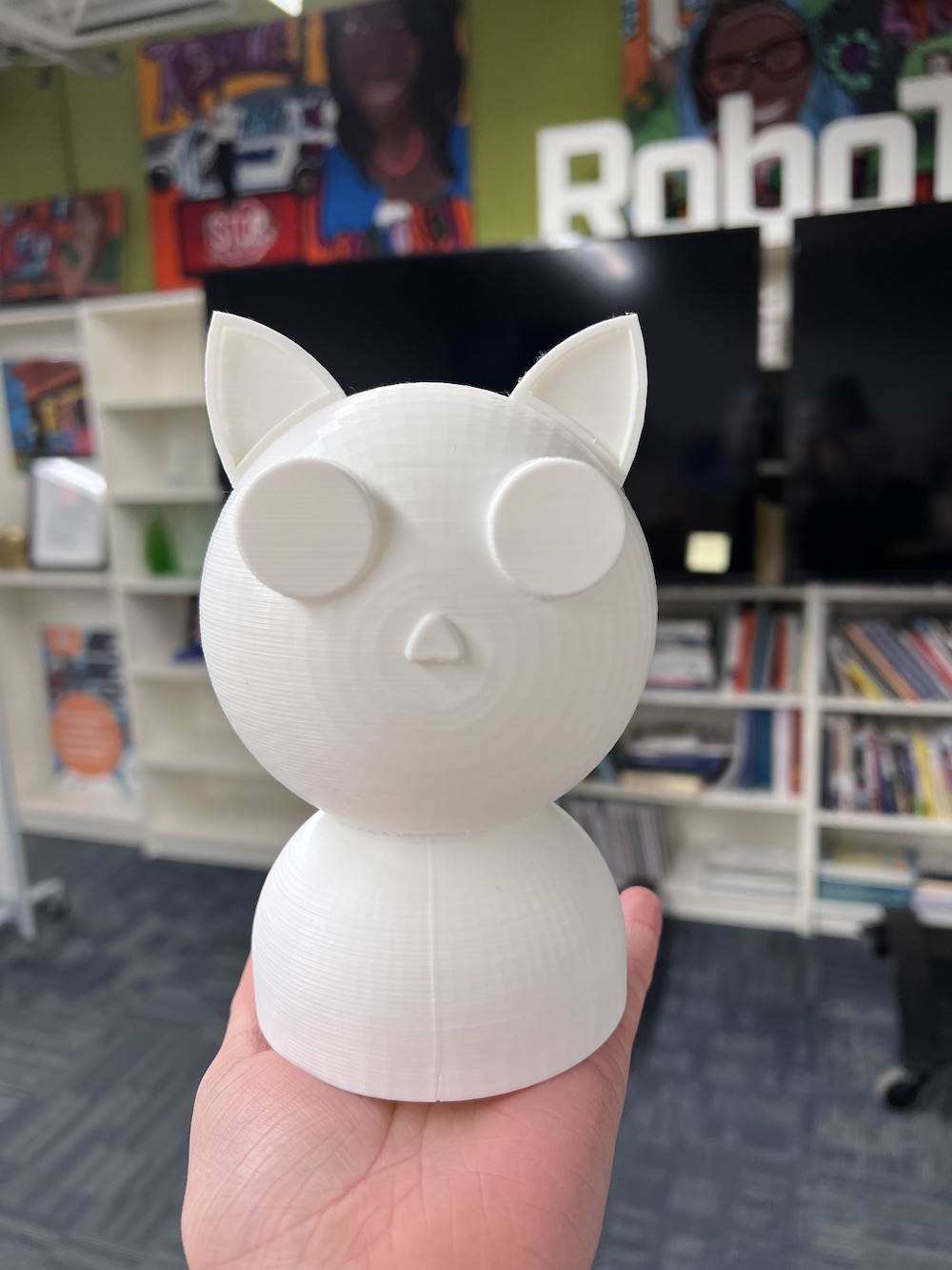
Cat Laser Desk Toy
My final idea is a laser toy I can program to shine around my room. Depending on what I can get done in a timely manner, I would love to be able to control it with a joystick. The purpose of it is mainly so I can use the toy to distract my cats while I am trying to get work done at home or around the house. Some of the features I'd like to include:
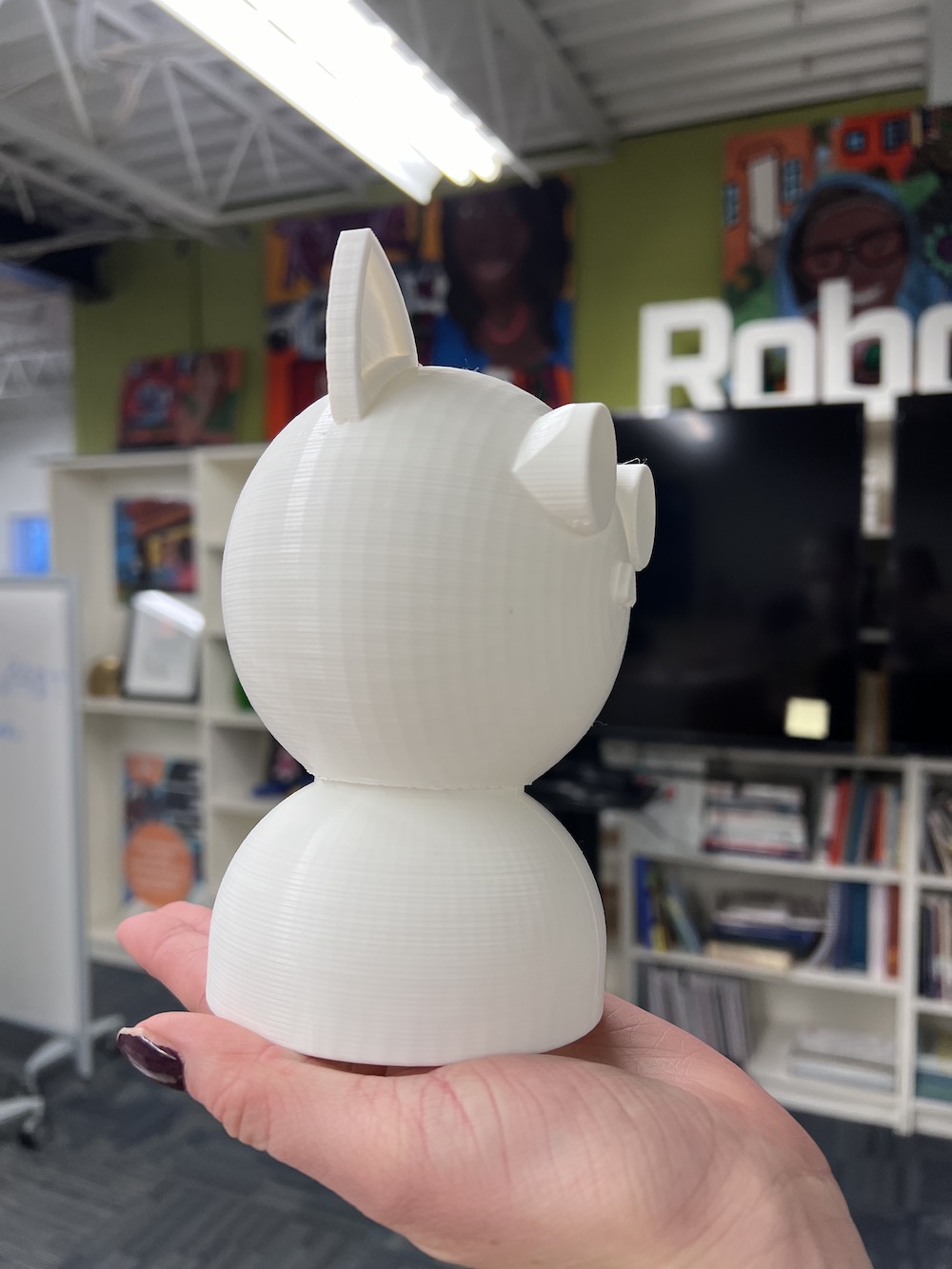
- 3D printed cat head
- 3D printed cat body & neck
- Laser cut housing for majority of electronics and to build stability in the base of my toy (so it doesn't topple off my counter or so my cats don't knock it off on purpose).
- Vinyl cut facial features and designs
- Customized PCB designed and produced in house.
- 2 continuous servo motors to control the X and Y movements of the laser. Output devices.
- 3D printed tail - hollow for wires and electronics to pass through.
- Remote joystick to control the servos. Input device.
- Laser component coming out of the tail or paw (depending on design).
Bill of Materials
| Material/Component | Price | Link |
|---|---|---|
| PLA filament | $18.99 | Amazon.com |
| Continuous Servo Motor (2) | $25.99 /5pcs. | Amazon.com |
| Colored Acrylic Sheets | $28.99 /10pcs. | Amazon.com |
| Hot Glue | $6.95 /1 glue gun and 10 glue sticks. | Amazon.com |
| Copper Clad PCB | $6.99 /10 pcs. | Amazon.com |
| Button - B3SN-3112p | $1.08 ea. | DigiKey.com |
| 510 Ohm Resistors | $39.90 for a 5,434 pieces (assorted resistors, capacitors, etc.) | Amazon Assorted Electrical Components |
| XIAO RP2040 | $5.40 | DigiKey.com |
| Pin head connectors | $12.78 /120 pcs. | Amazon.com |
What does it do?
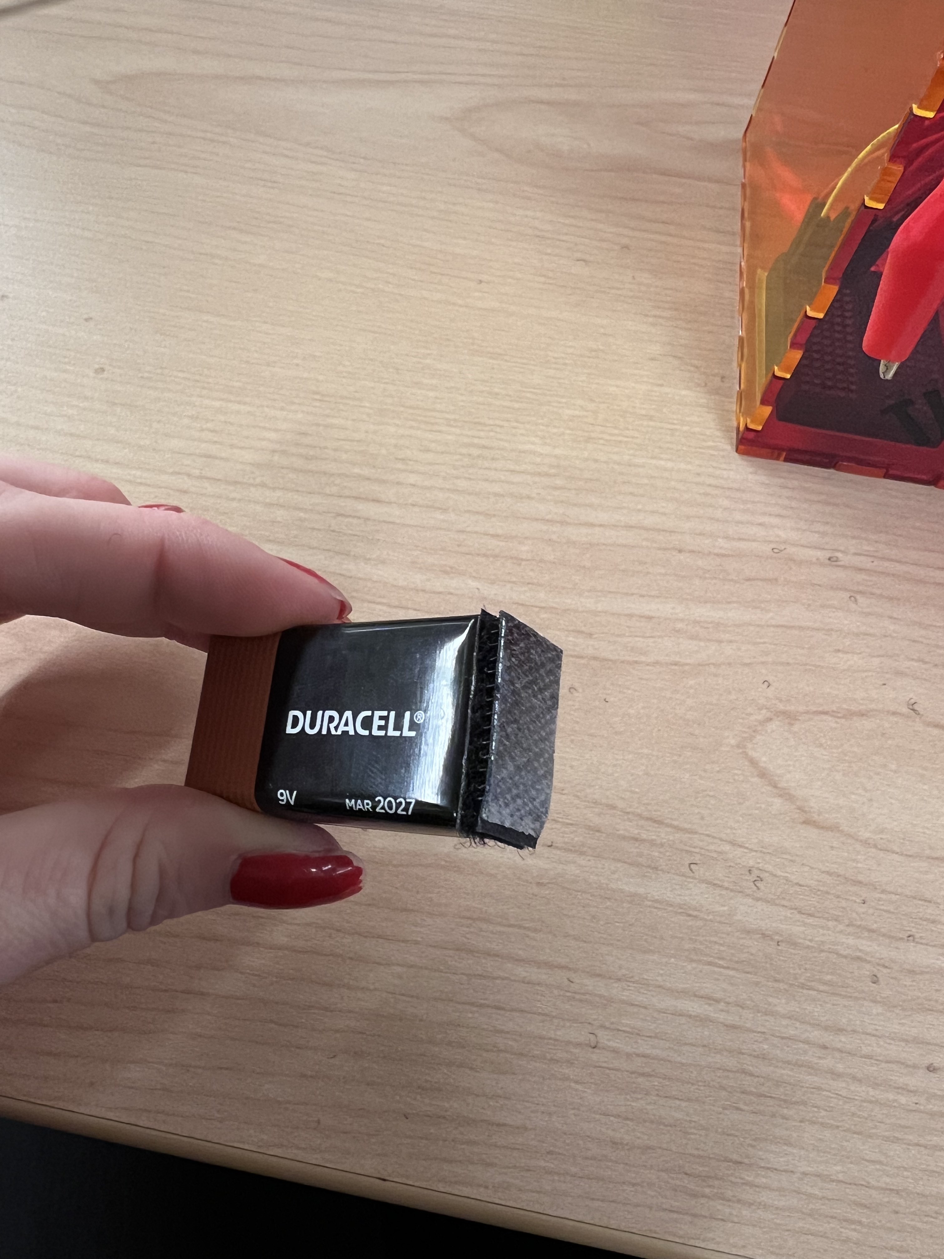
My final project is a cat shaped toy that moves its paw and waves hello. It also will have a function on the paw to fit a laser pointer that will move around. The paw is programmable- the two servos (one controlling X movements, one controlling Y movements) can be coded through Arduino IDE to be randomized, you can put limits on the size of your area for the laser dot, or can just program it to wave a gentle hello! It is like a little desk friend to keep me company and a laser pointing toy to keep my cats distracted in one! The XIAO RP2040 on my custom PCB has a 5V power capability. The servos are powered by a 9V battery. The servos can move 180 degrees in the X and Y directions respectively.
The license I chose is a Creative Commons Zero (CC0). This particular license means that I revoke my copyright and the work I produce and publish will be available for use in any fashion from the public. Part of why I chose this license is because a lot of the projects I quite enjoyed, used a similar license, and I think its inspiring when people have open-websites that anyone can use information from. I don't want to gatekeep information or make a profit for this; I want this to be a project anyone can pick up and try.
Here are the kitties that I would like to entertain with this toy!


If your kittens are anything like mine, they will LOVE your Christmas tree. This is one thing I would like to distract them from with this toy!
What's been done before?
A few designs for similar toys do exist on the market currently. Some of their limitations are in the range of motion they have, the visual appearance/aesthetics of the design, and cost. Some current ideas I have feature cute, interchangable facial vinyl stickers, the moving paw which I haven't seen before, and easy access to the electronics via the sliding box top. I will provide a link below to some example toys that exist currently.
- Chewy.com PetSafe Dancing Dot Laser Cat Toy
- Chewy.com PetSafe Laser Tail Laer Cat Toy
- Amazon.com Cat Laser Toy Automatic, Laser Light/Cat Toy
- Amazon.com AUKL Cat Laser Toys for Indoor Cats
What processes were used?
Subtractive Fabrications:
- Computer-Aided Design (CAD) and Computer-Controlled Cutting (CCC) - Laser Cutting a box for housing electronics and to serve as a base for the toy to remain level on a flat surface.
- CCC - Vinyl Cutting facial features, whiskers, paw print, and toy name for the box and aesthetics.
Additive Fabrications:
- CAD: 3D printing -
- Cat Body
- Cat Head
- Cat Arm
- Cat Paw
3D Scanning:
I made a model paw out of air dry clay that I will scan with a 3D scanner and use as a guide/model in Onshape. This will allow me to keep the approximate size and shape of the paw, but make the model a little smoother. I will also adjust the sizes ever so slightly to make sure the servo will fit inside, and will have an area to attach to on the inside of the paw. Having this connection to my servo will give my paw the Y movement that I need.
Two days before due date update: the 3D scanner has not yet arrived so I am unable to scan the paw I made. So sad, but I dont want it to go to waste, so I am debating using it, by drilling and shaping out the inside to fit the electronics, or uploading an image to Onshape of the paw next to a ruler so I can accurately model the paw. The only issue with the latter option is it has shown to require more skills in Onshape than I thought that I had. I hope to accomplish this, as it would be a good way to measure my growth in CAD skills, but we shall see.
Final update: I did not end up including 3D scanning or the clay paw I made into my final project. Further down in this page I will go into detail about my solution.
Electronics Design, Production, and Programming
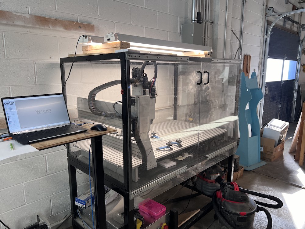
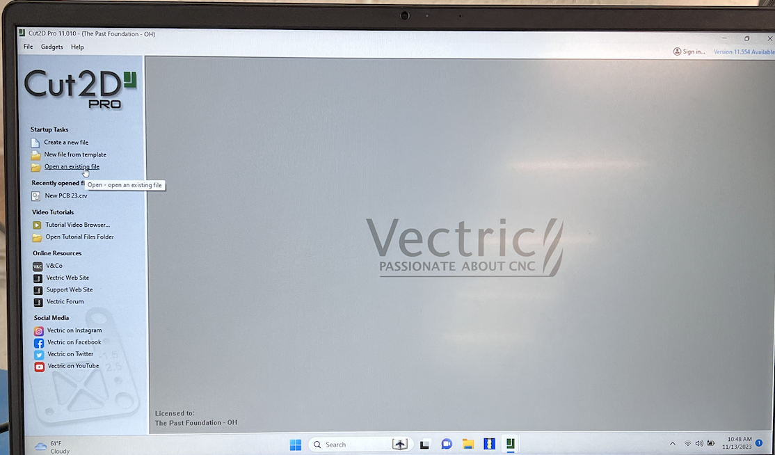
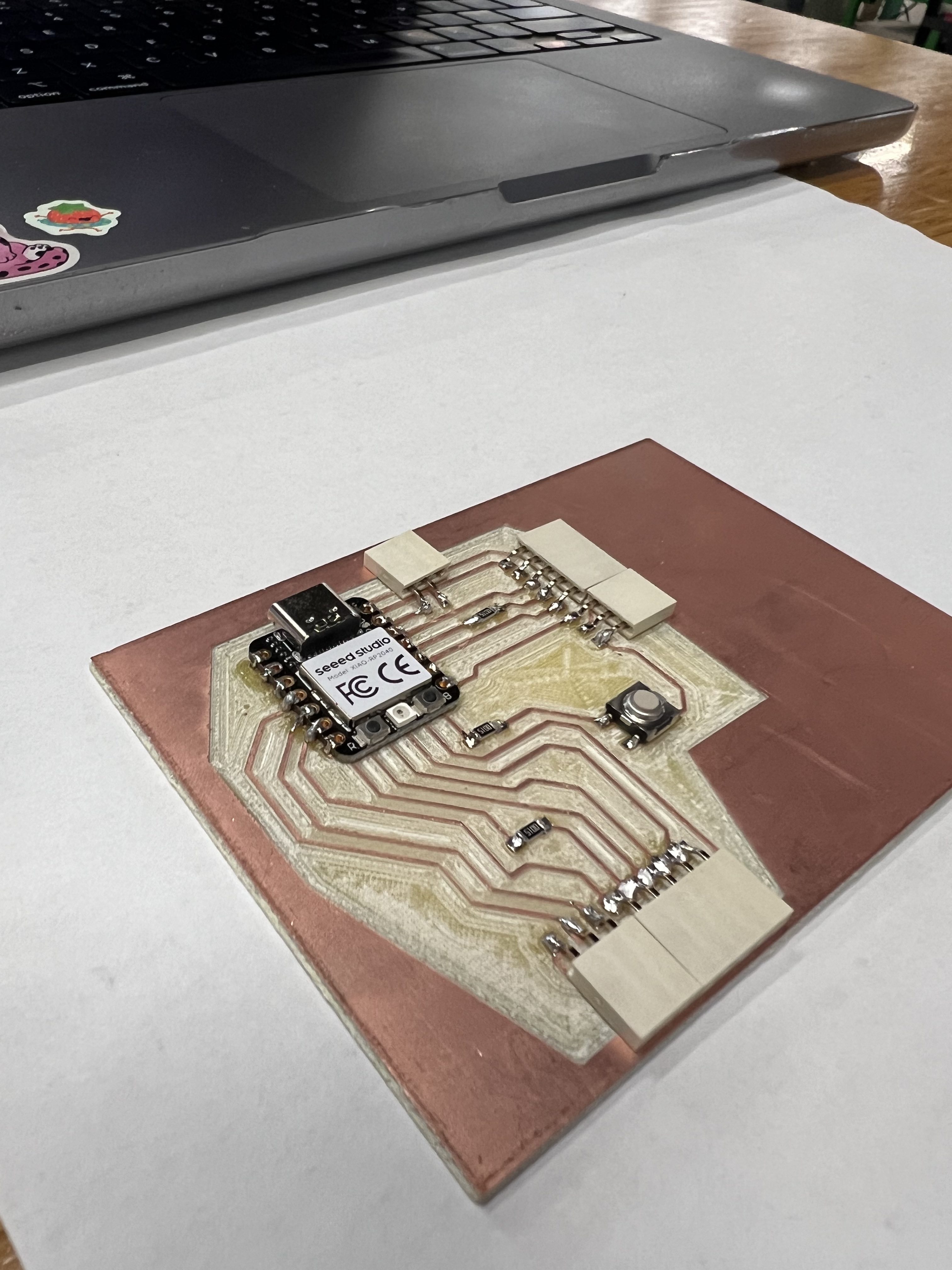
I used Kicad to design my PCB. I exported this as a SVG to a flash drive and take it to the Windows computer we have attached to our Forest CNC machine in our shop. On there, I used Cut2D Pro to create the toolpath, and send it to the CNC application on the laptop. This is where I set my X and Y homes and ranges, and my Z, and make sure it is all ready to go. The PCB was milled and I was able to solder my components onto the board.
Next, I will wire the servos to my board and find and modify codes to control the two servos simultaneously. I am hoping to use the application Processing to have an interface the user will interact with.
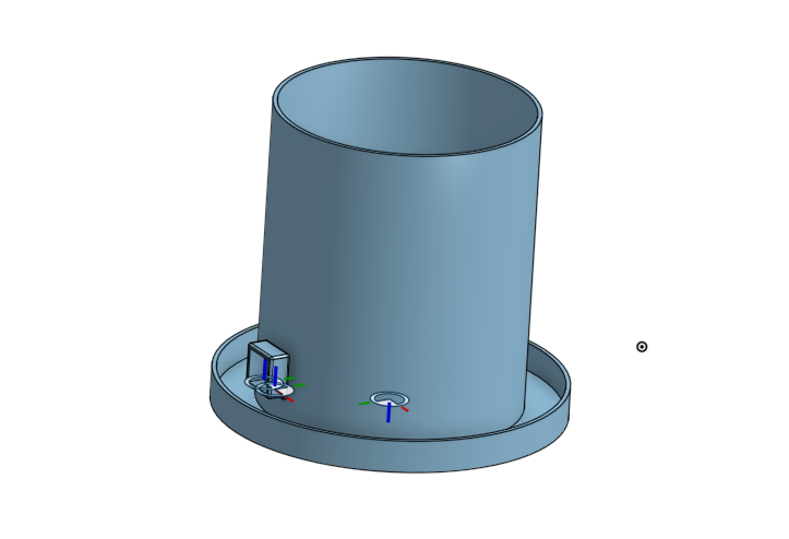
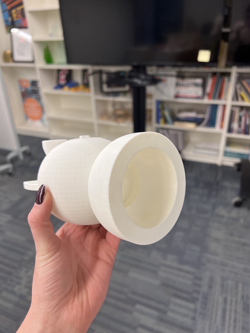
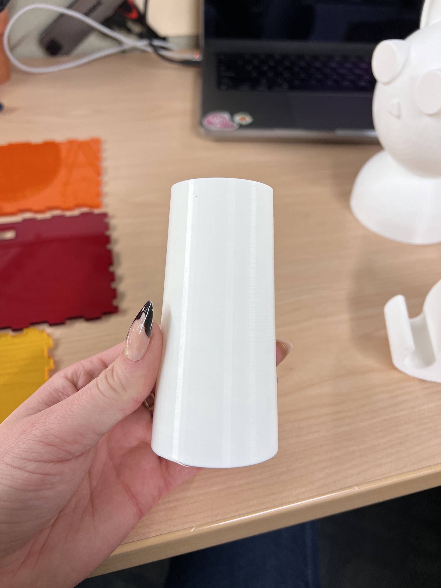
3D Printing
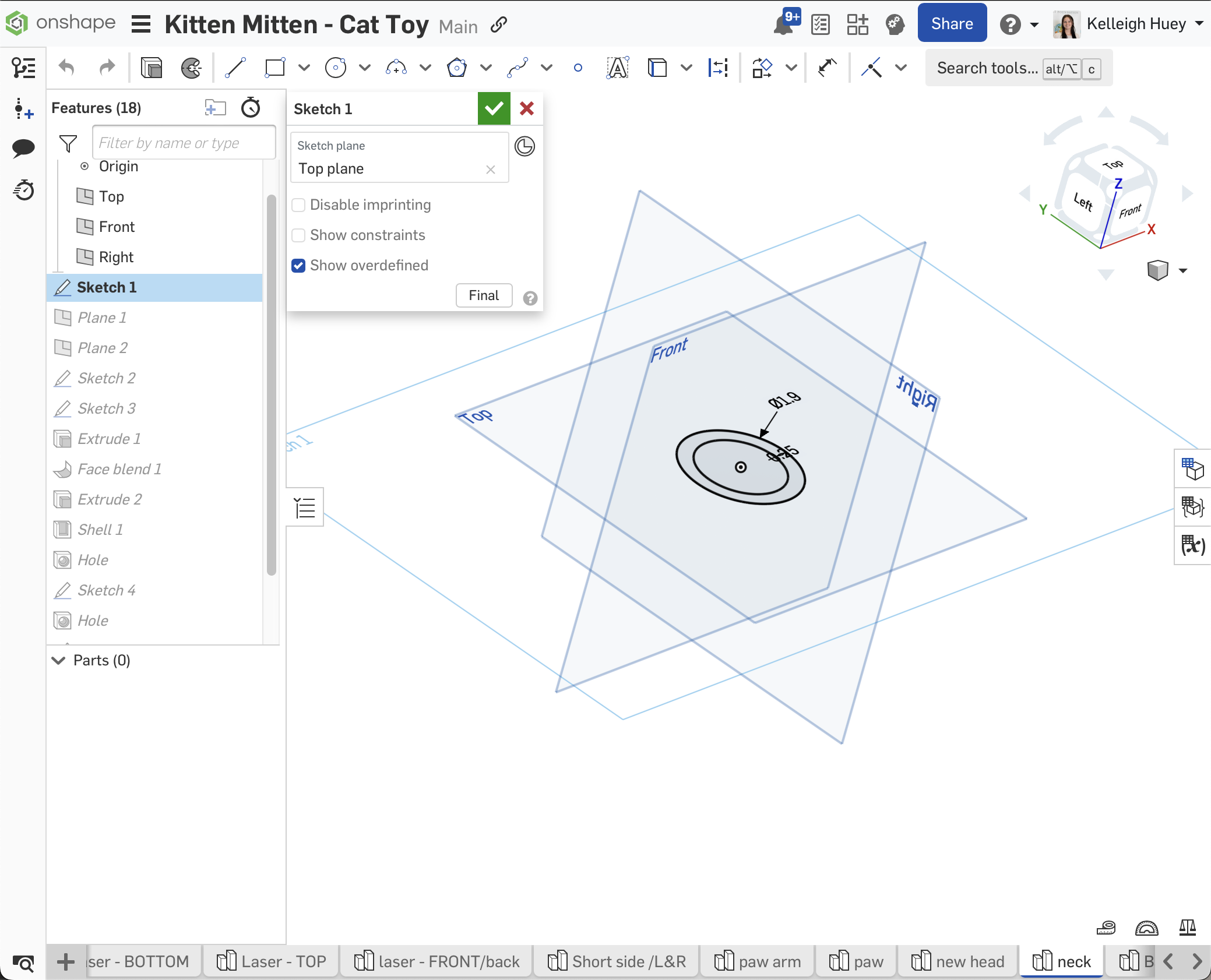
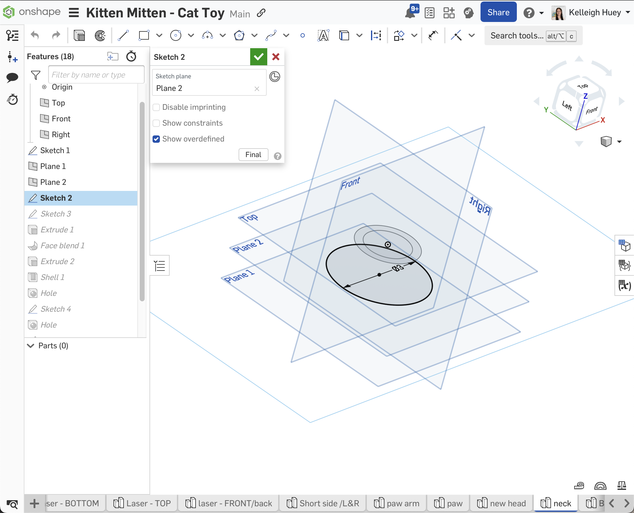
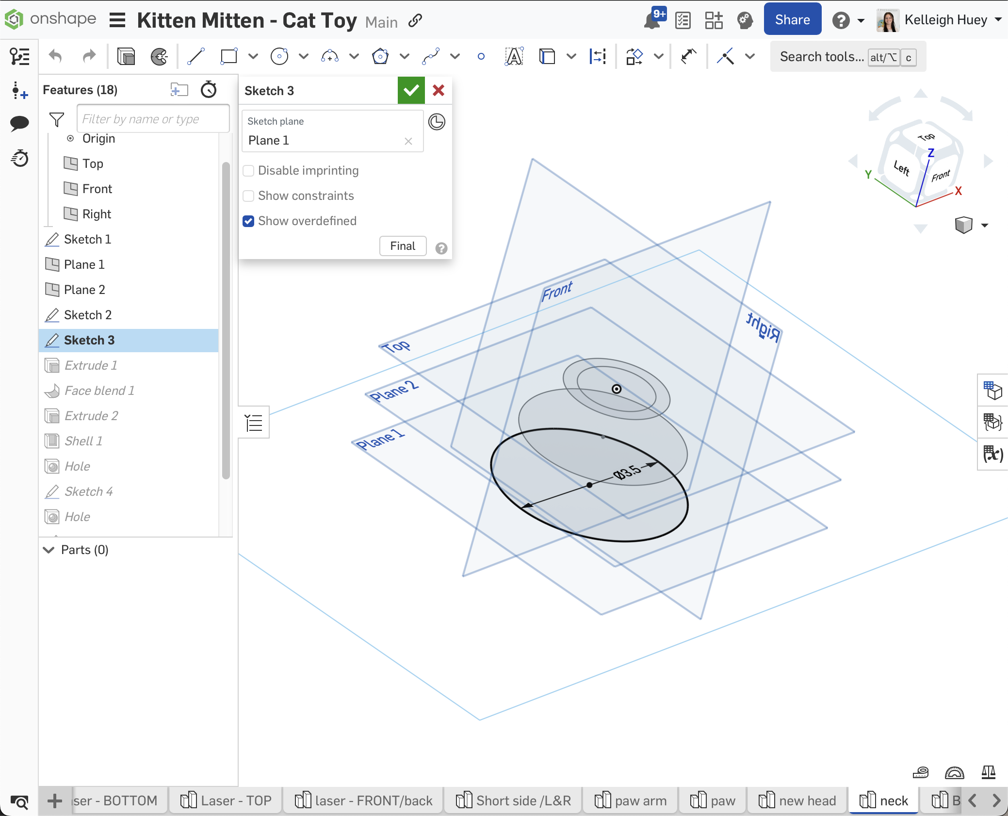
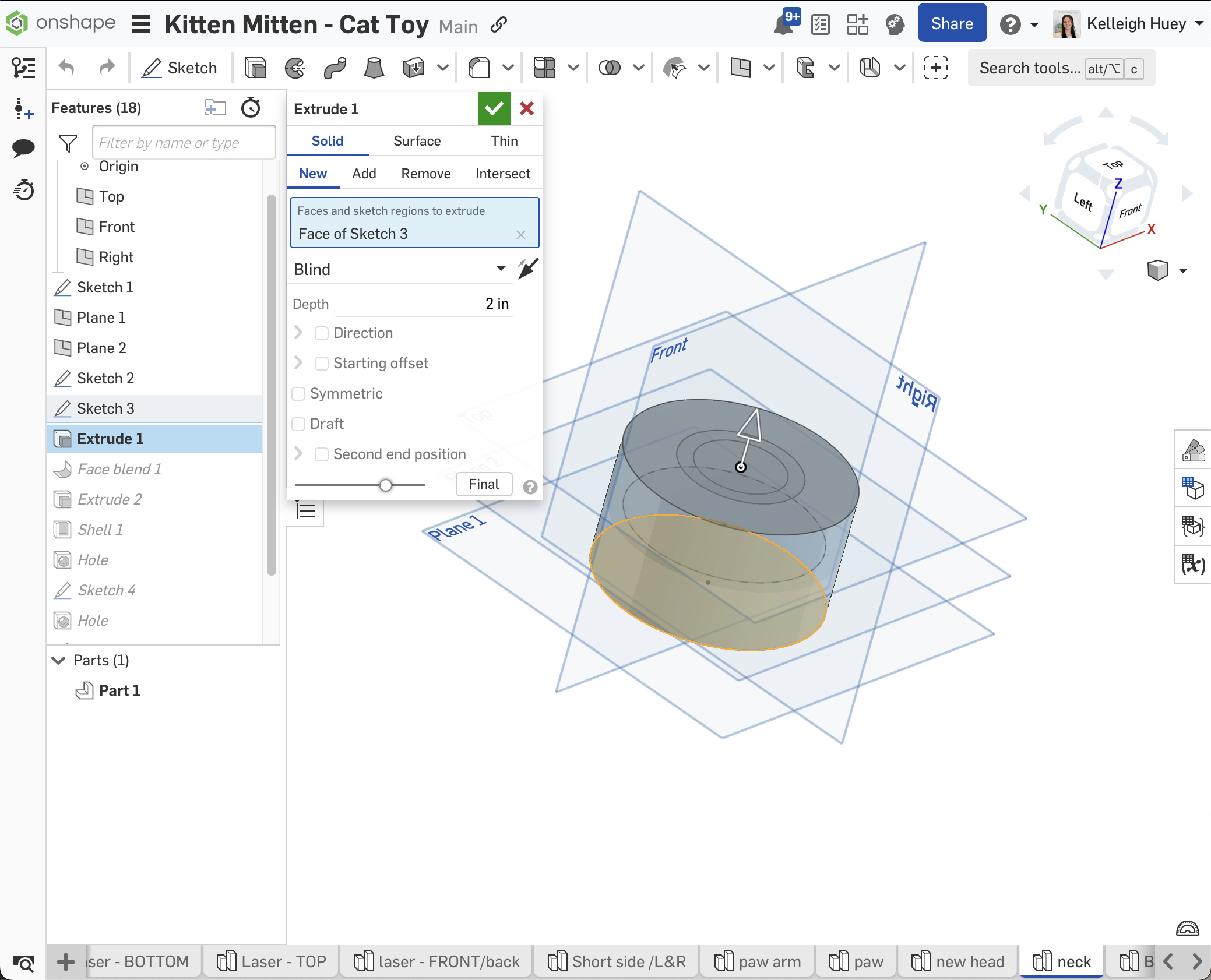
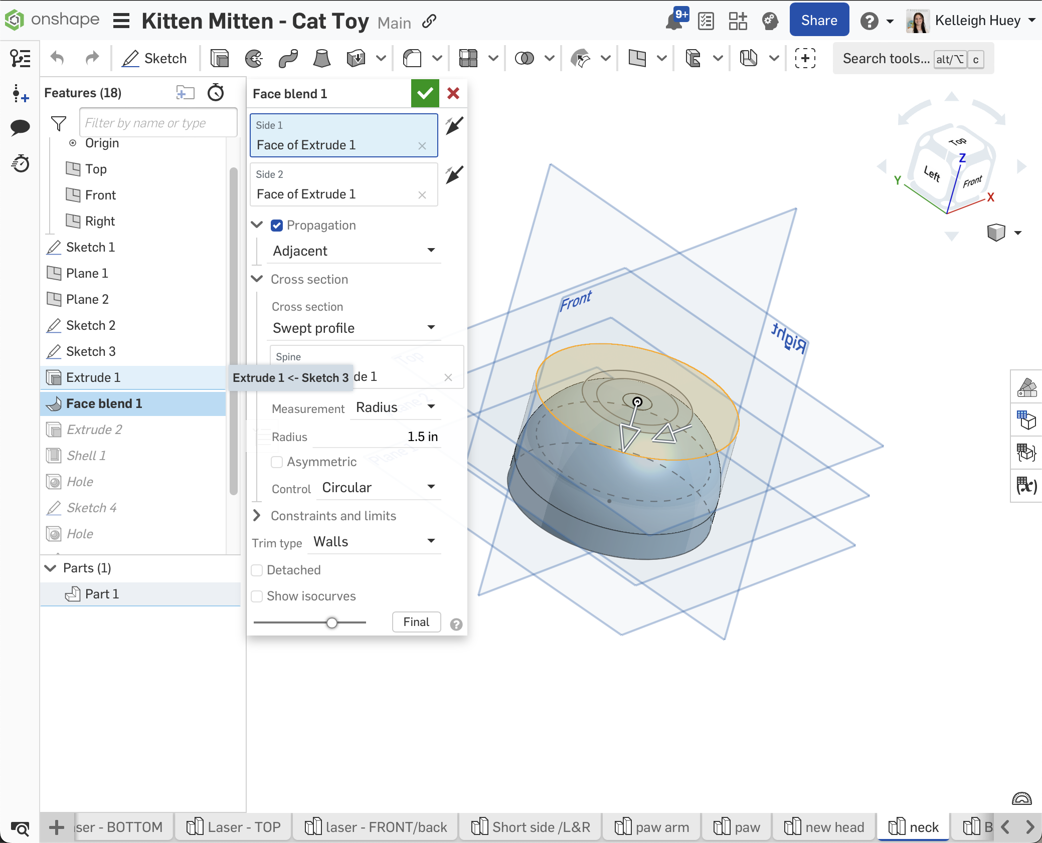
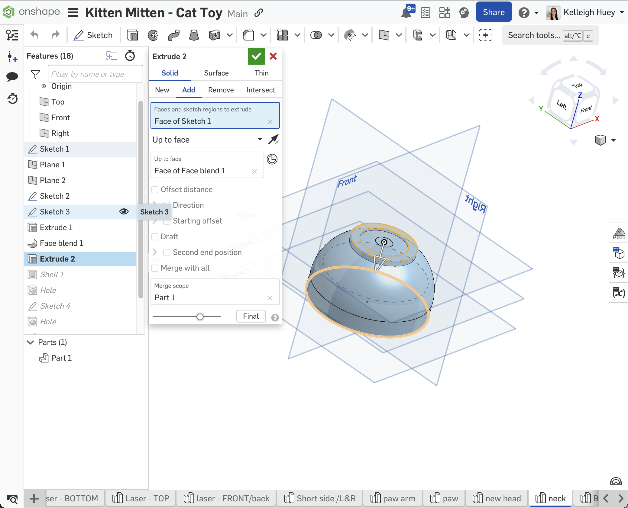
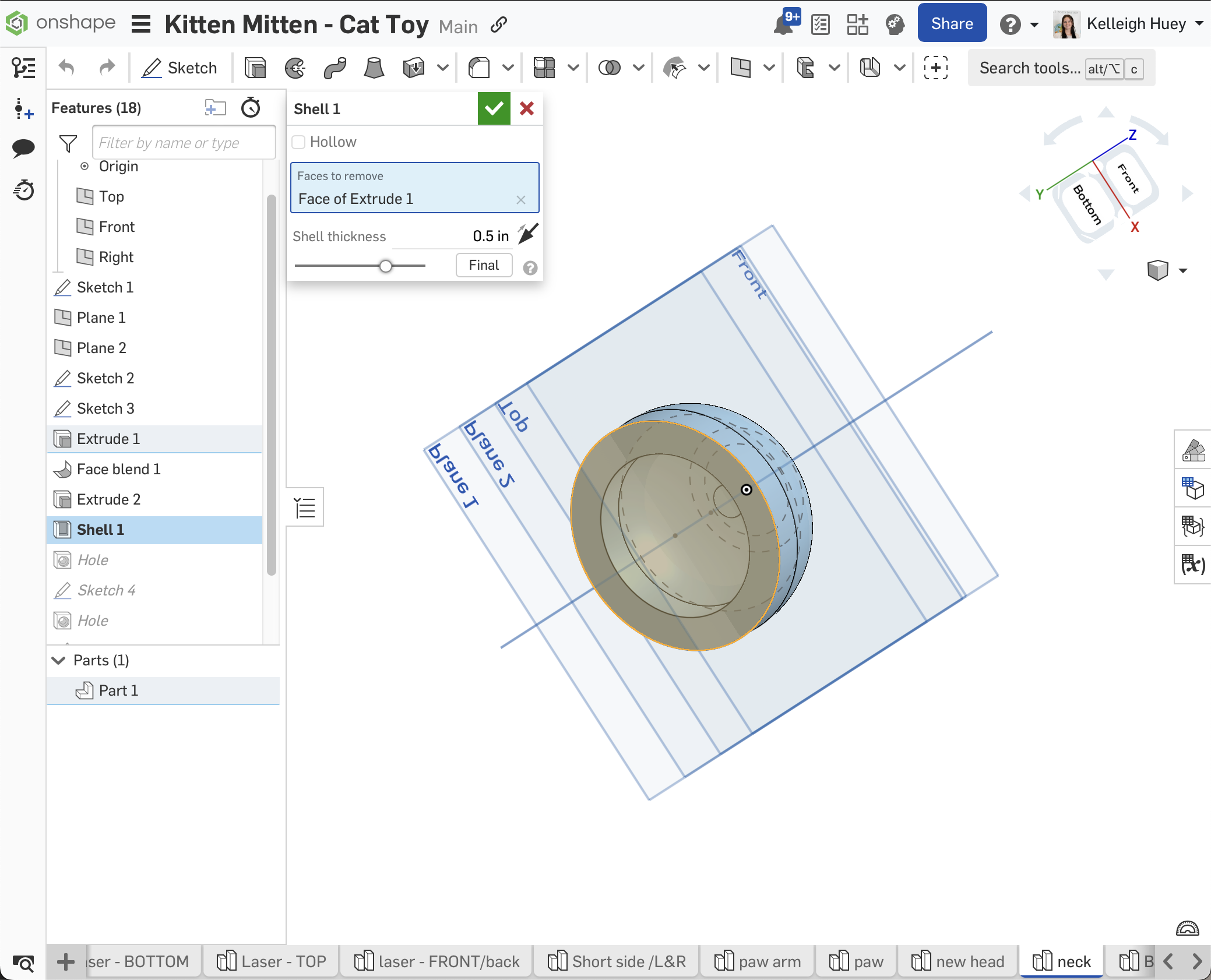
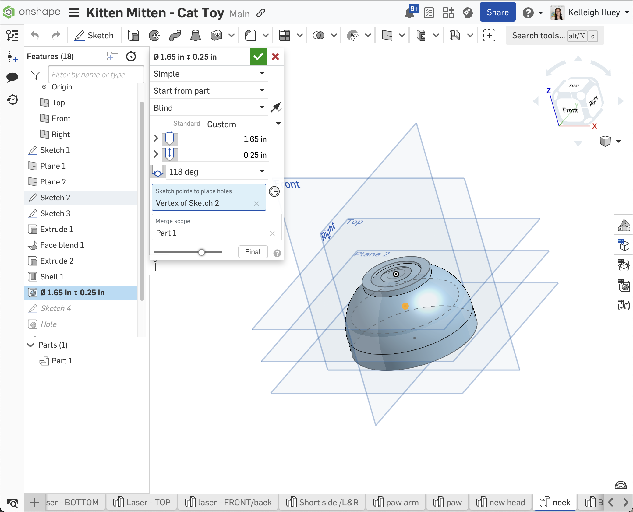
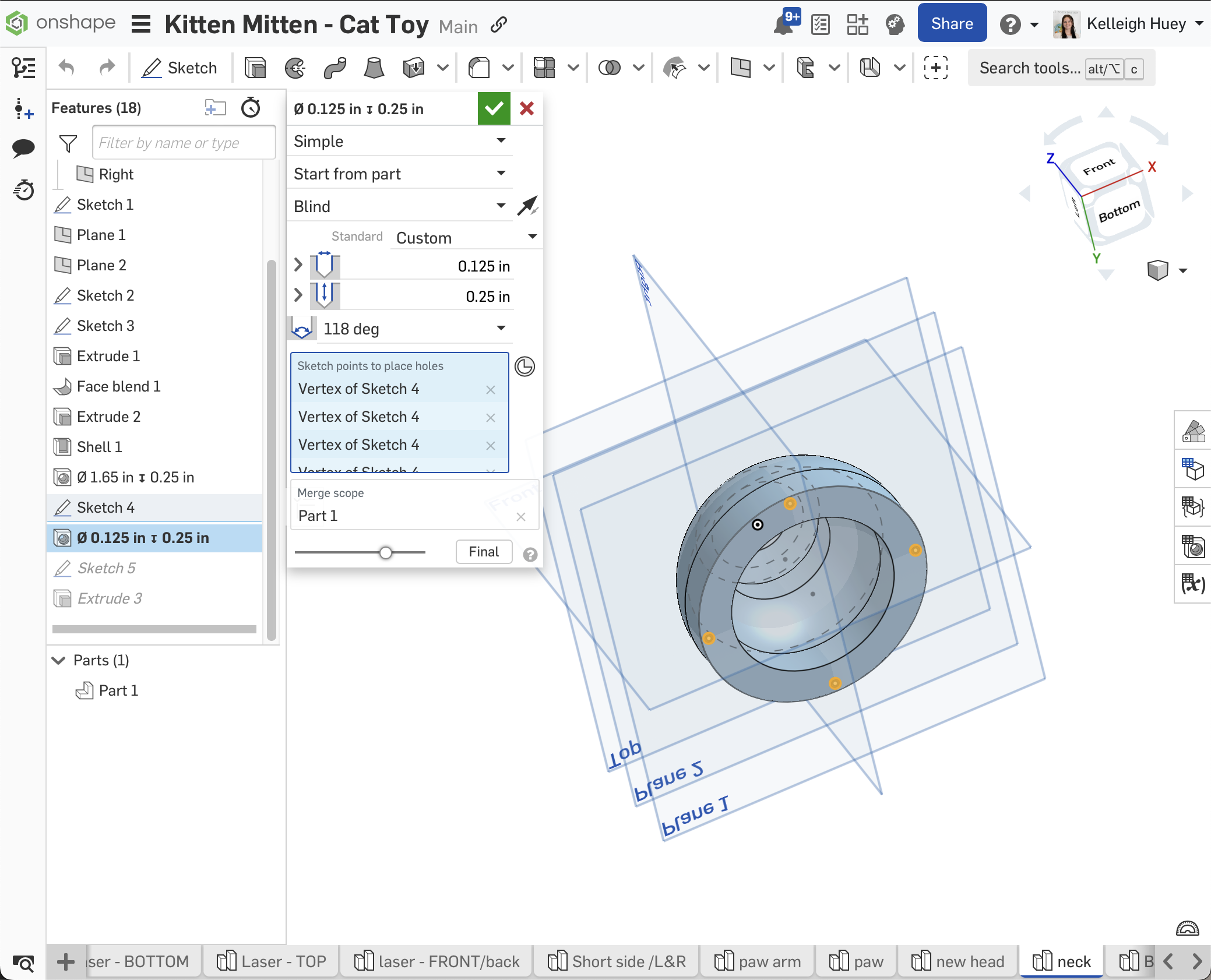
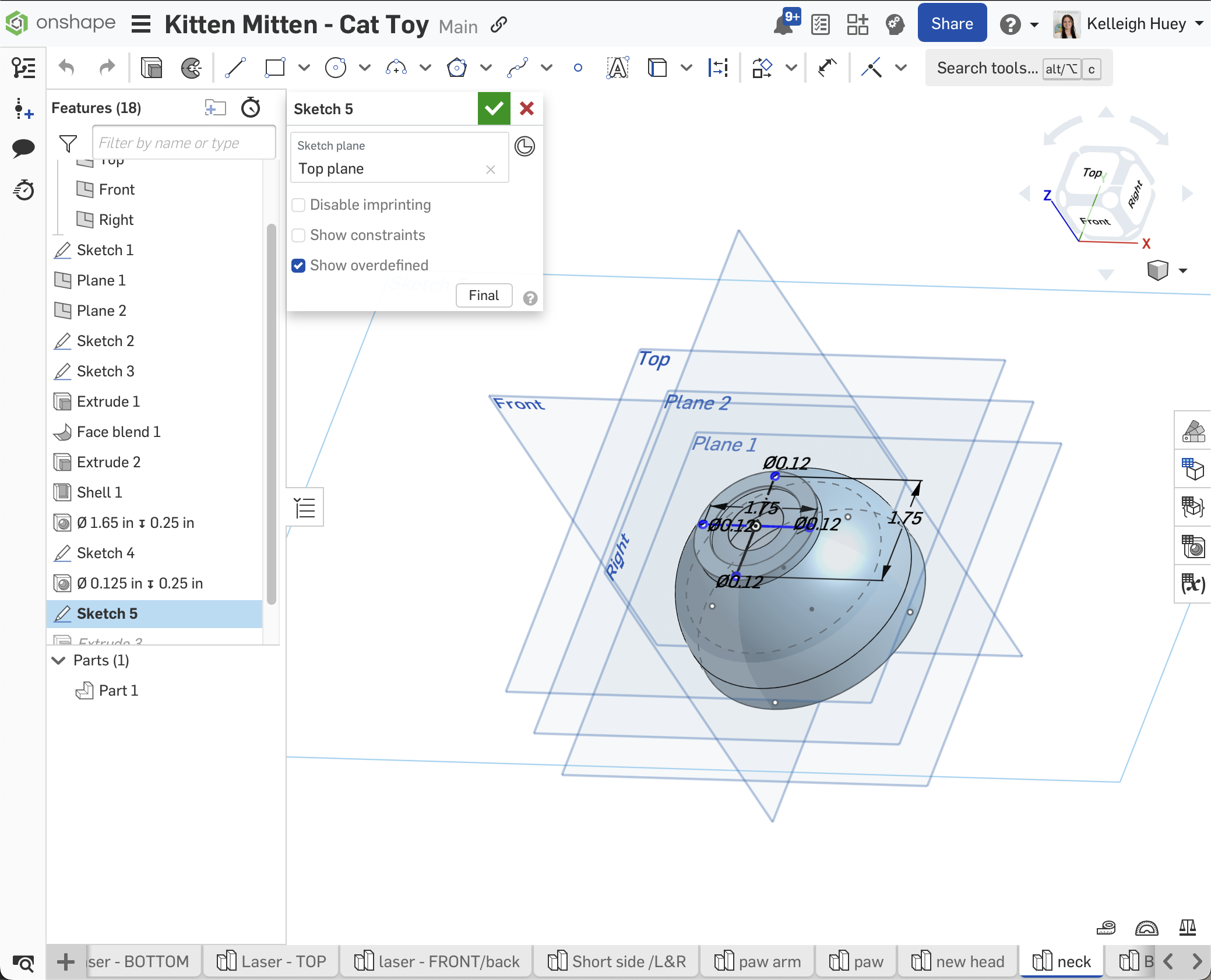
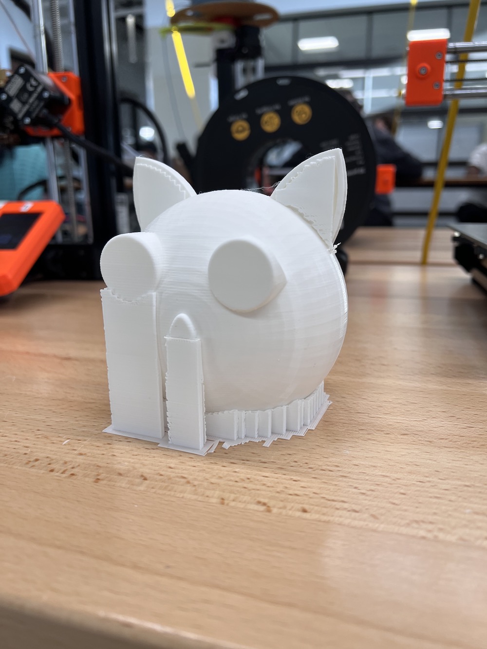
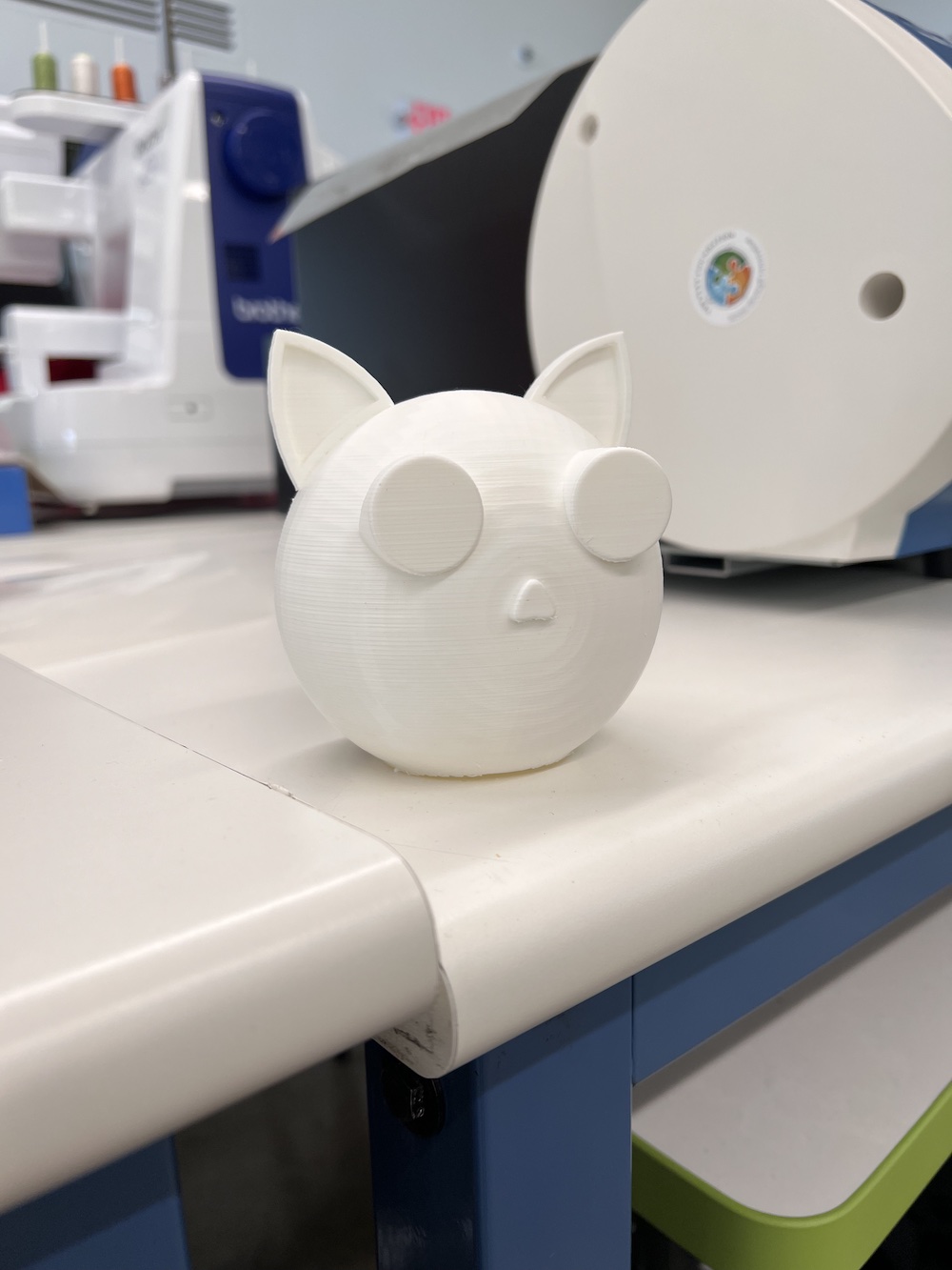
I have printed my head and neck/body to my cat project. I did not have any errors in design or printing these parts so far. To do this, I used computer-aided design to make the model in Onshape, then exported the STL file to PrusaSlicer, to slice the object for 3D printing. There, I added supports to ensure nothing would go wrong during printing. Before printing a full size, I printed a scaled down version to make sure the hole on the head was the proper size. I have to print my arm and paw next. Below is a scroll gallery for the process of making the 3D model of the arm. It is an example of the processes required in creating a 3D shape in Onshape. More information is available on my week 2 - Computer-Aided Design page.
OnShape Files
Successful Prints Photos
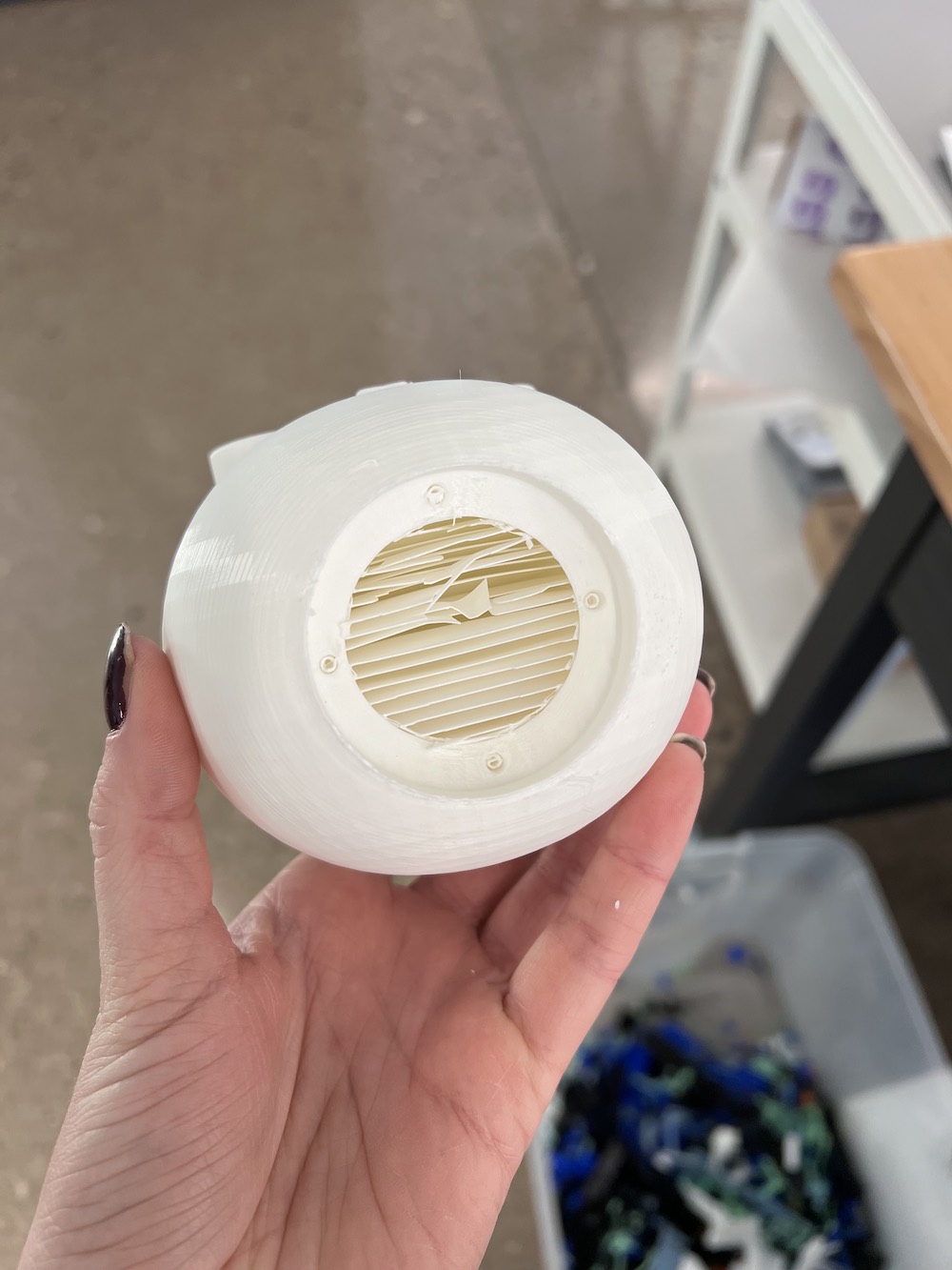
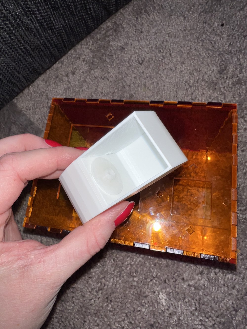
This final image is of the interior of the final paw design I made for the project.
Some CAD and 3D Printing hiccups I overcame...
I only ran into issues with CAD when it came to the paw. It also wasn't really any big issues, just adjusting the size of the interior shell (to house the servo motors), adjusting the size of the paw itself (so it did not hit the cat head when in motion), and making sure I had a flat surface to secure the servo attachment to.
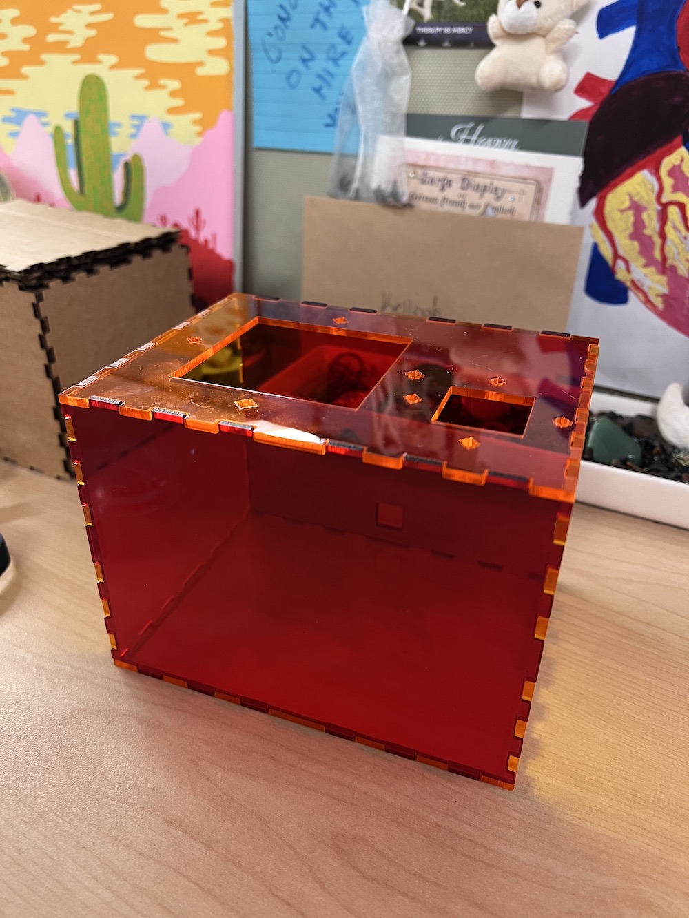
Laser Cutting
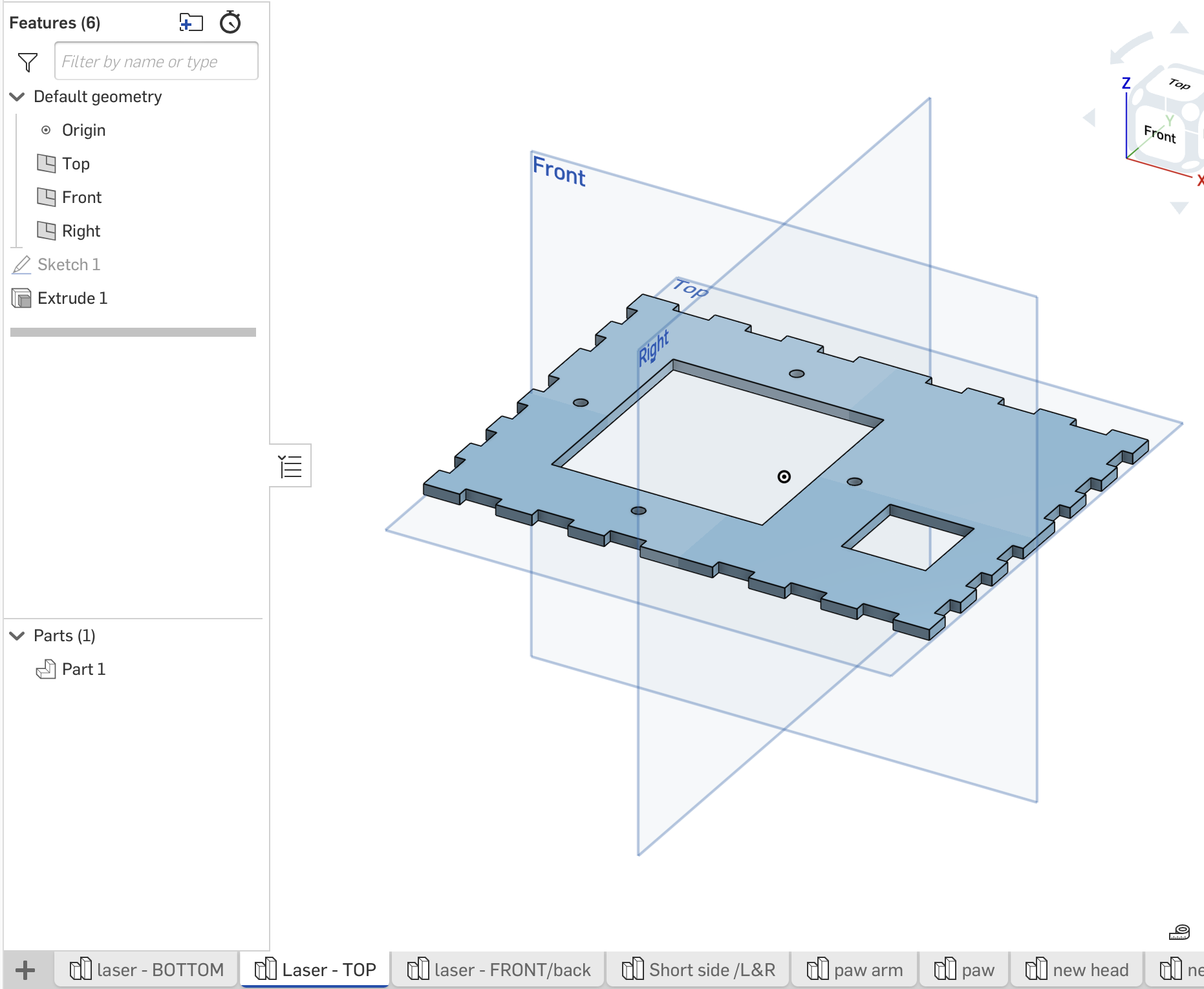
In the scroll gallery below, you will find some sample screenshots from designing the laser cut box. I only included two of the sides for time and my repository size sake. For more information and details on how to create a box like this, see my Week 3 Assignment Page. I used Onshape to create the design and dimension it properly. Some of the main tools you'll need in creating a box like this in Onshape are the "Sketch" and "Extrude" tools to create the shape and give it 3 dimensions. The other tools are "filet", "shell", "hole", and "revolve" for examples.
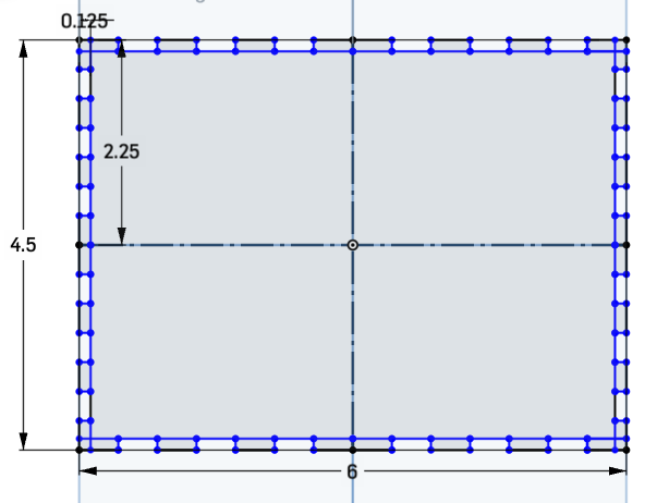
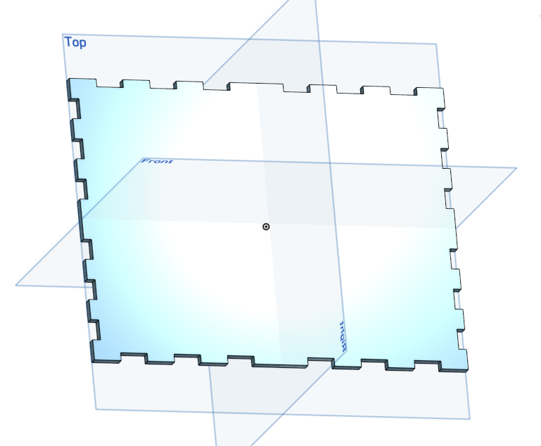
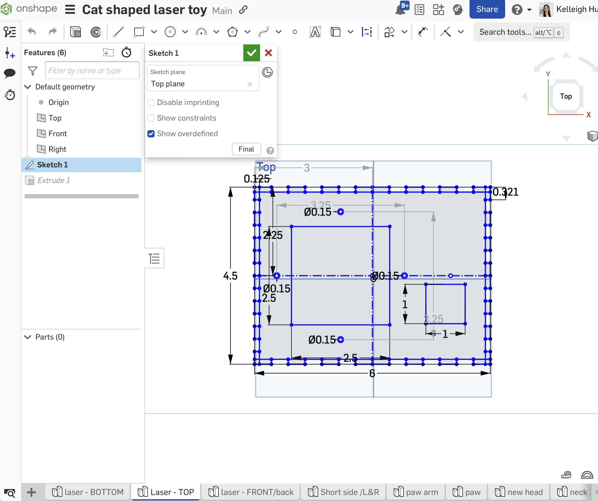
In the last two pictures above, you will see a mistake I made while I was modeling. I accidentally removed and then extruded the wrong sketch box in Onshape. On the left side, the middle tab I should have is not centered, and therefore will make an ill-fitting box.
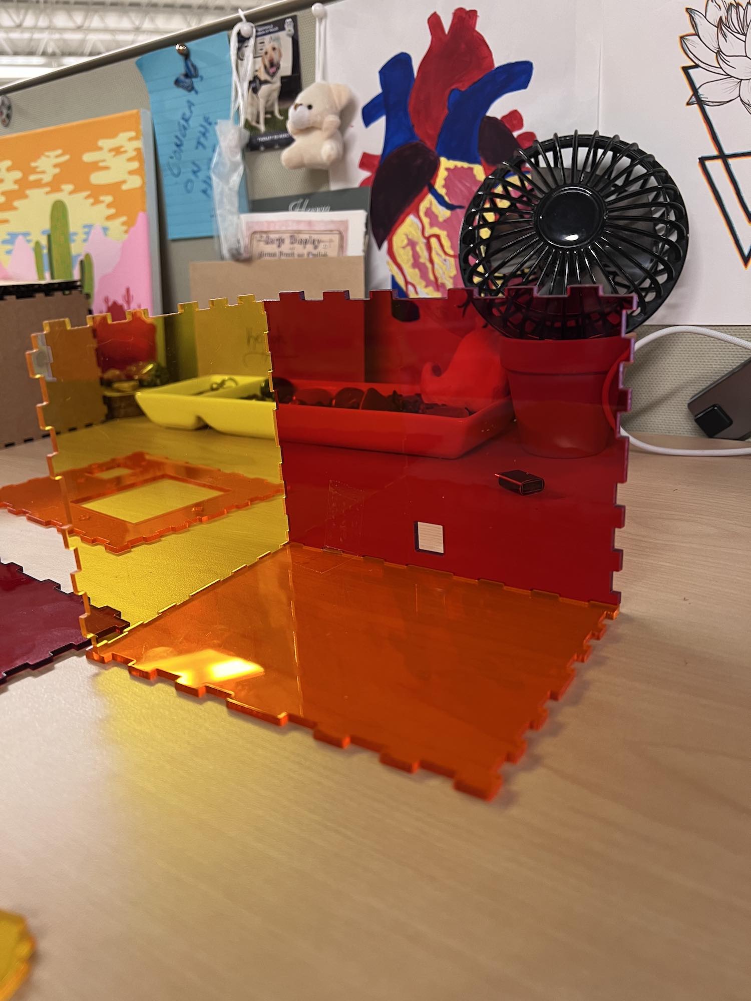
I made adjustments in Onshape to my box, and have acrylic sheets to cut it out from. Below are some images of the final box.
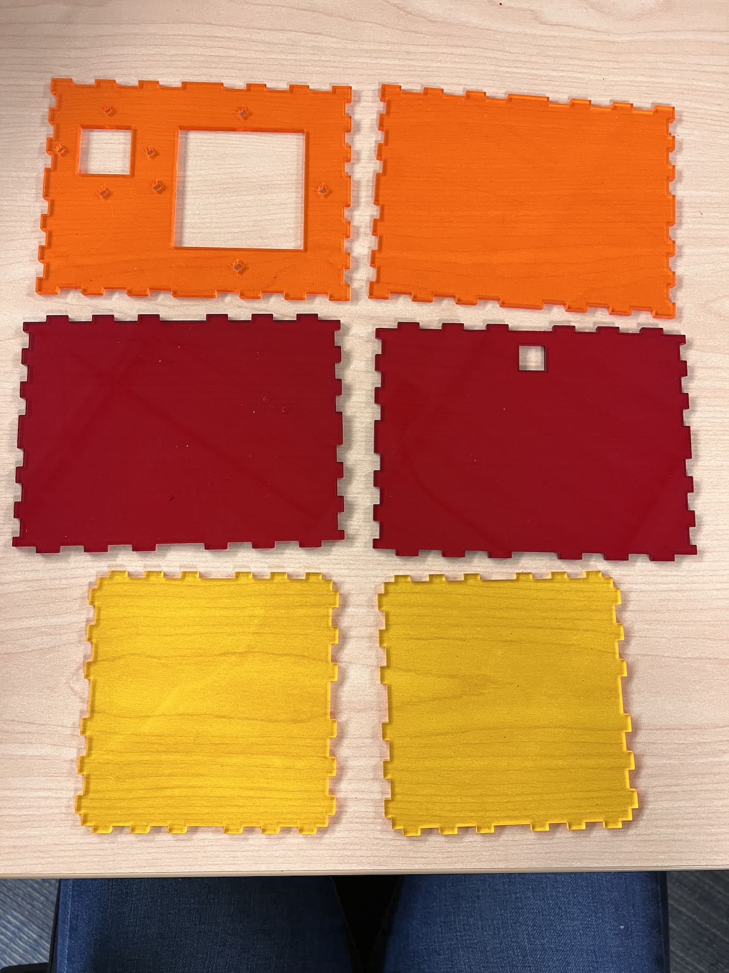
Laser Cut Files
Below are the files I used. One top, one bottom, one for both sides (cut two of this), one for the front and one for the back.
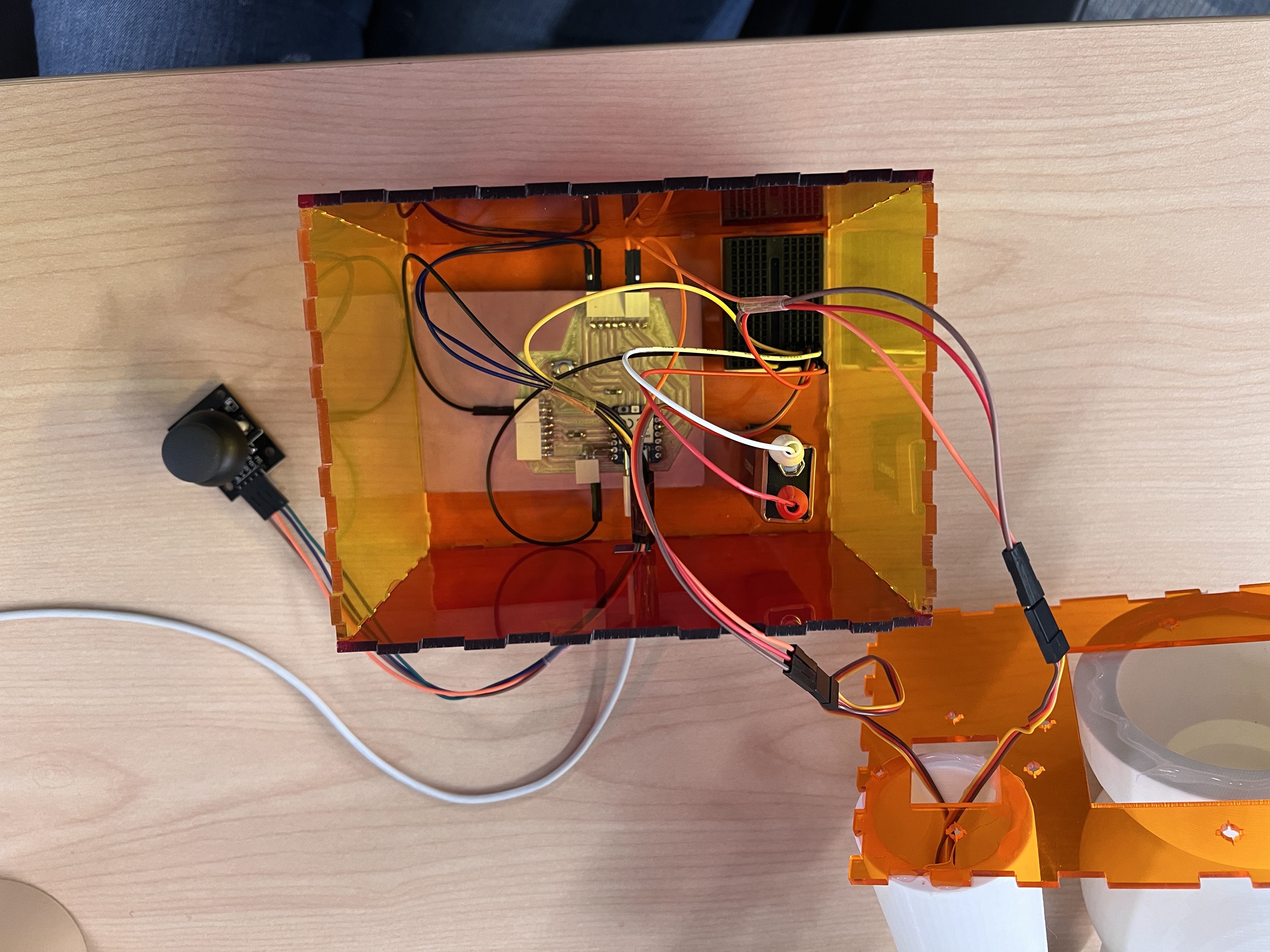
Electronics
Below, I am breaking down the electronics components into the following subsections: PCB Design, Production, and Programming. You will find a gallery and information associated with each below.
Helpful electronics weekly pages
week 8 - Electronics Production
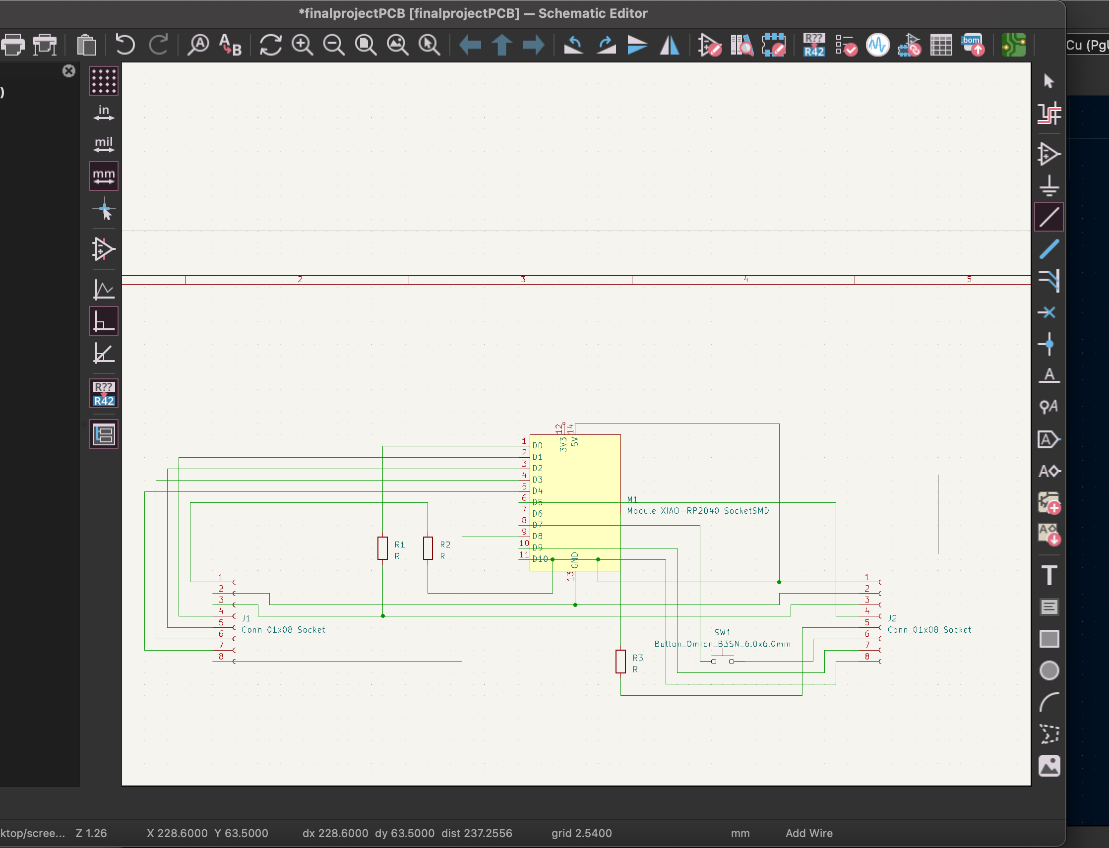
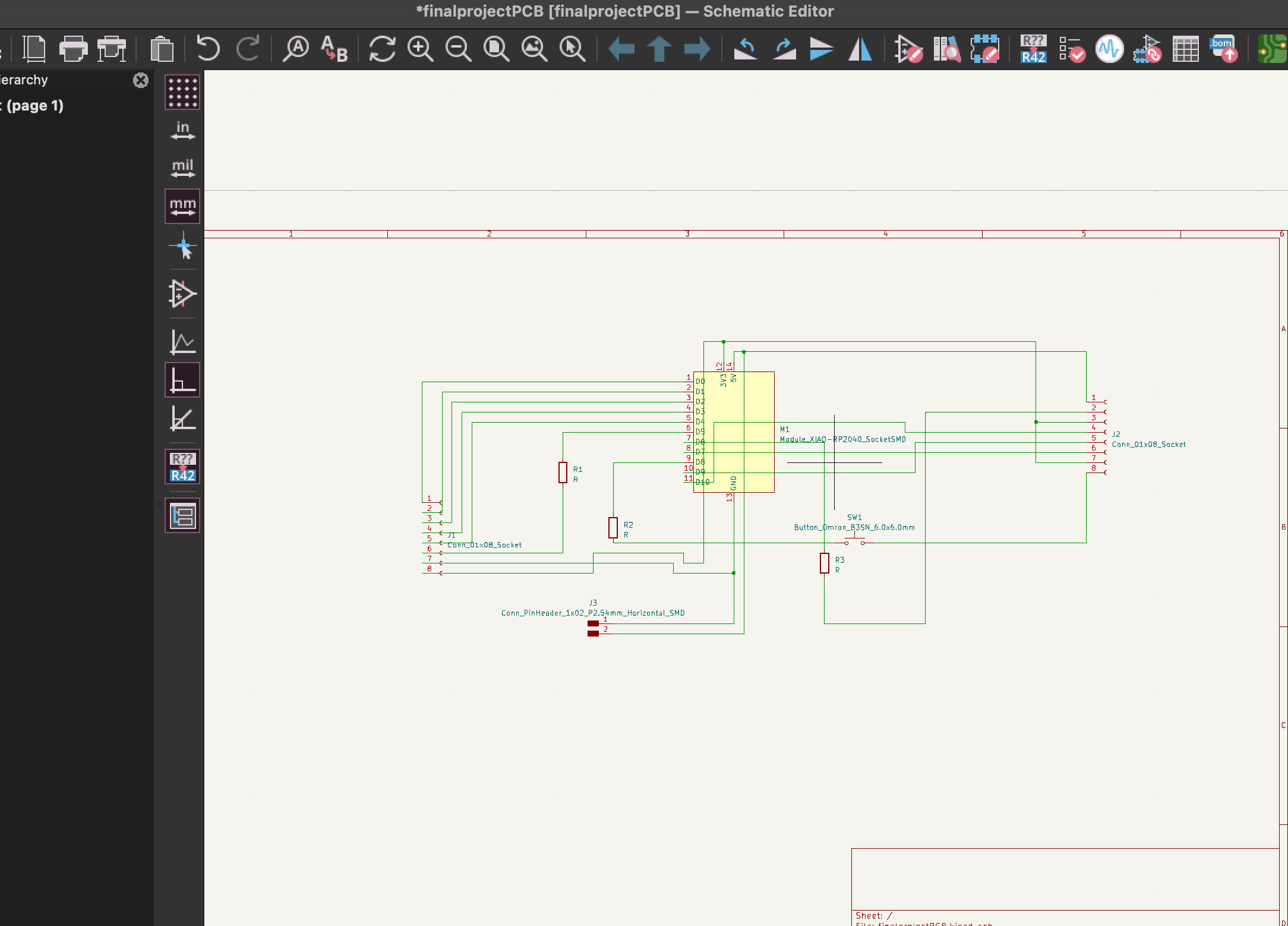
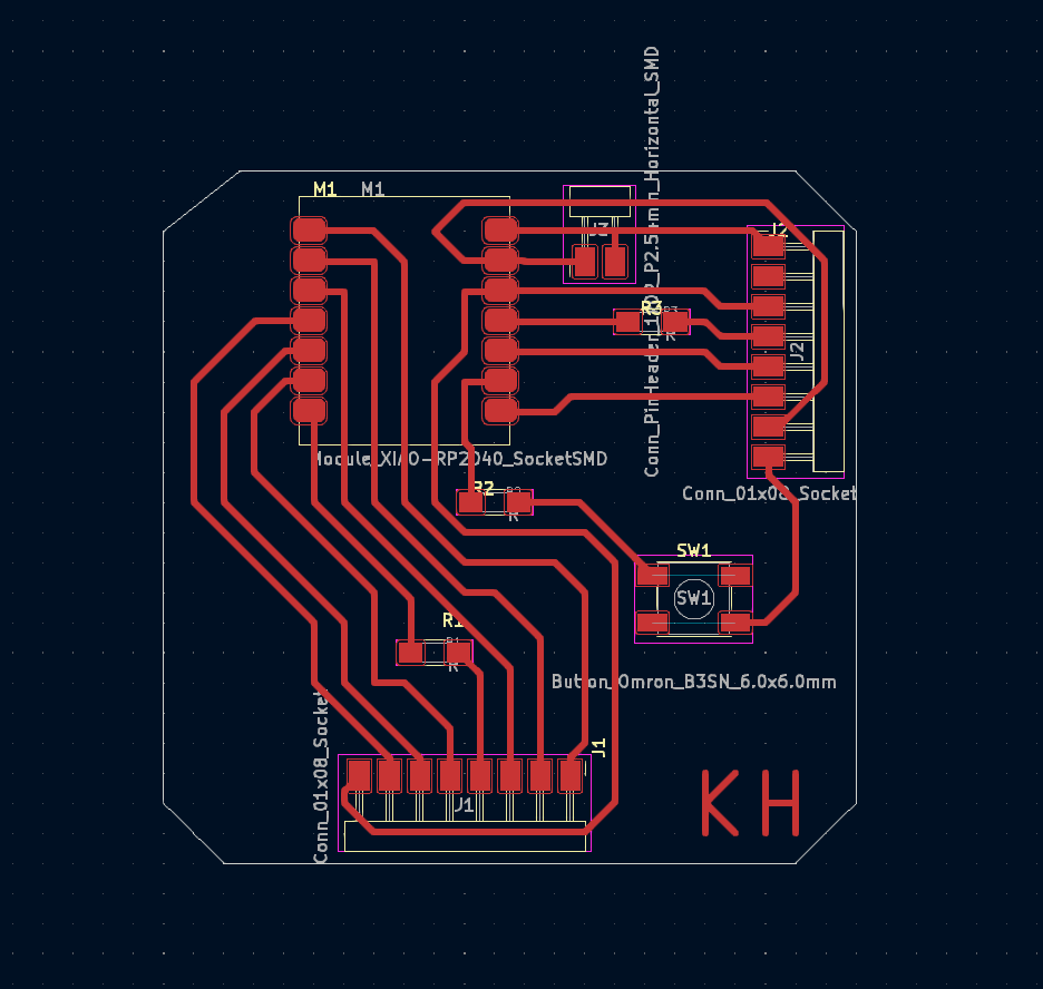
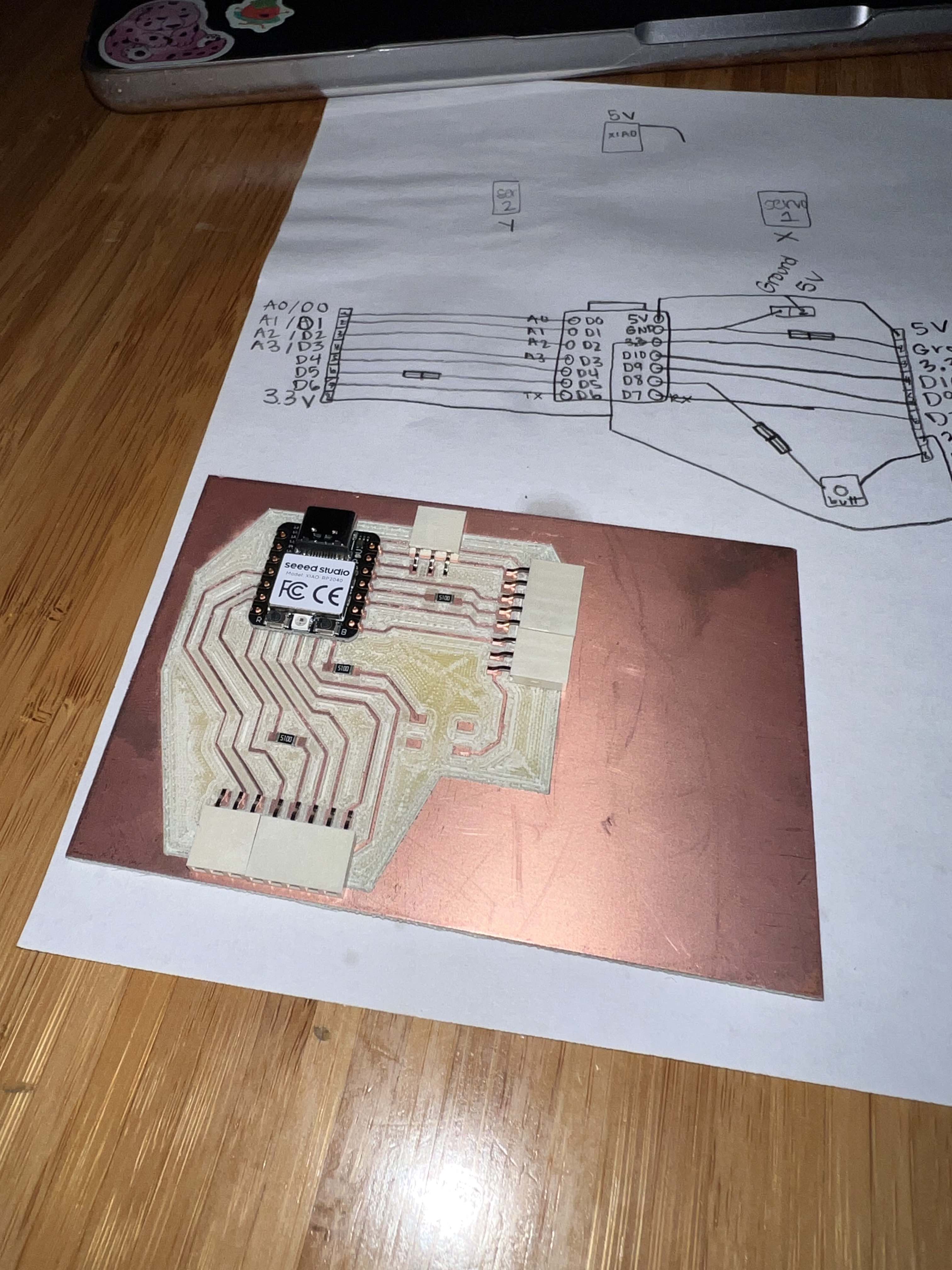
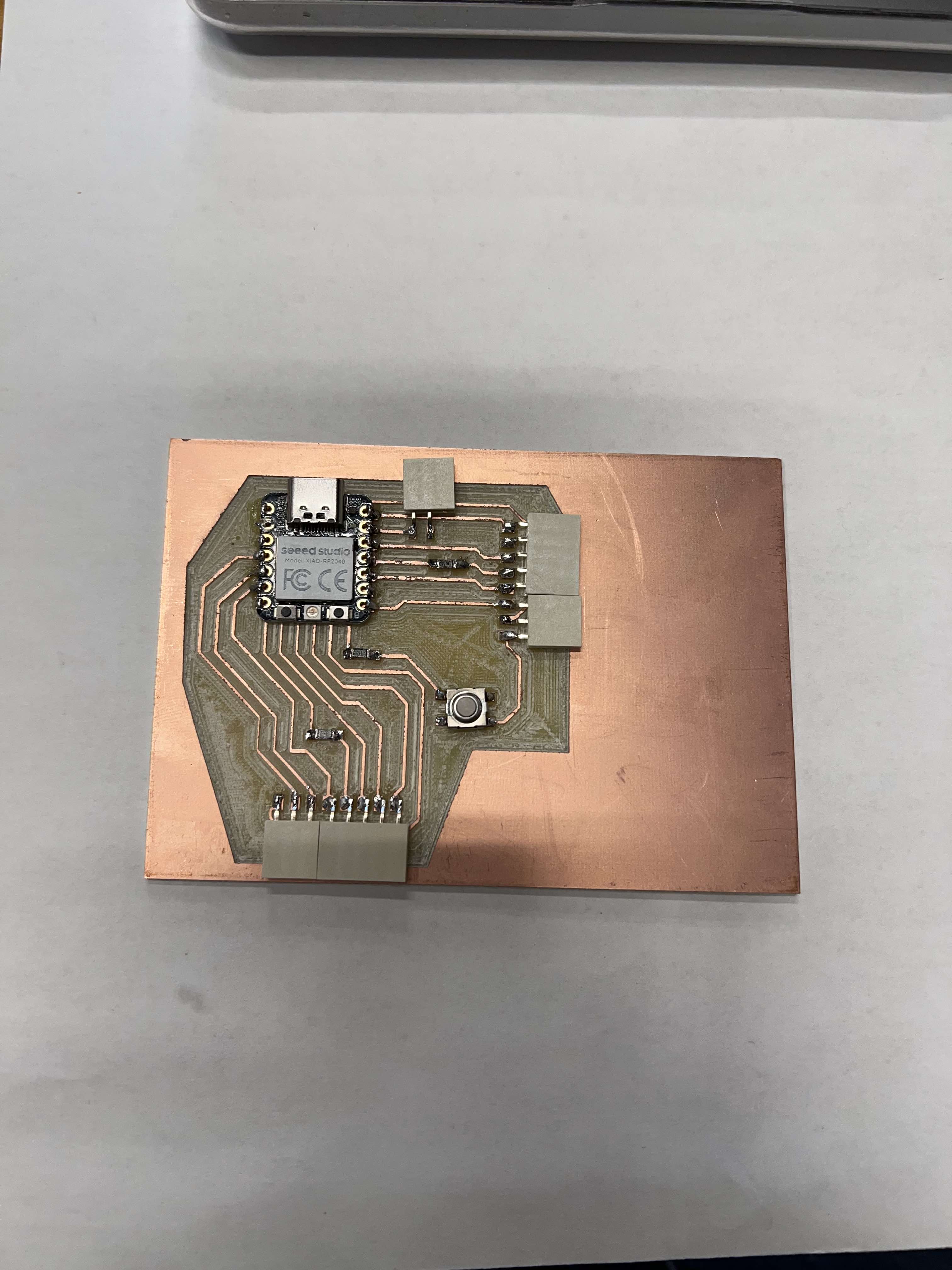
Kicad - PCB Design
I have used Kicad to design my PCB. I knew that I needed to have enough pins connected to my 5V on my XIAO RP2040 and I know that I needed to have multiple grounds, as well as digital and analog pins available for use at any time, in case I ever come back to this project and wish to upgrade or change it I will have some options.
In Kicad, I added my microcontroller symbol and footprint, two 8 pin head connectors, one button, three resistors, a two pin head connector and their footprints. I did this in the Schematic editor of a new project that I saved to my desktop. I added wires to each of the pins and through the resistors where I desired and once the wiring was done, I transferred it to the PCB editor in Kicad.
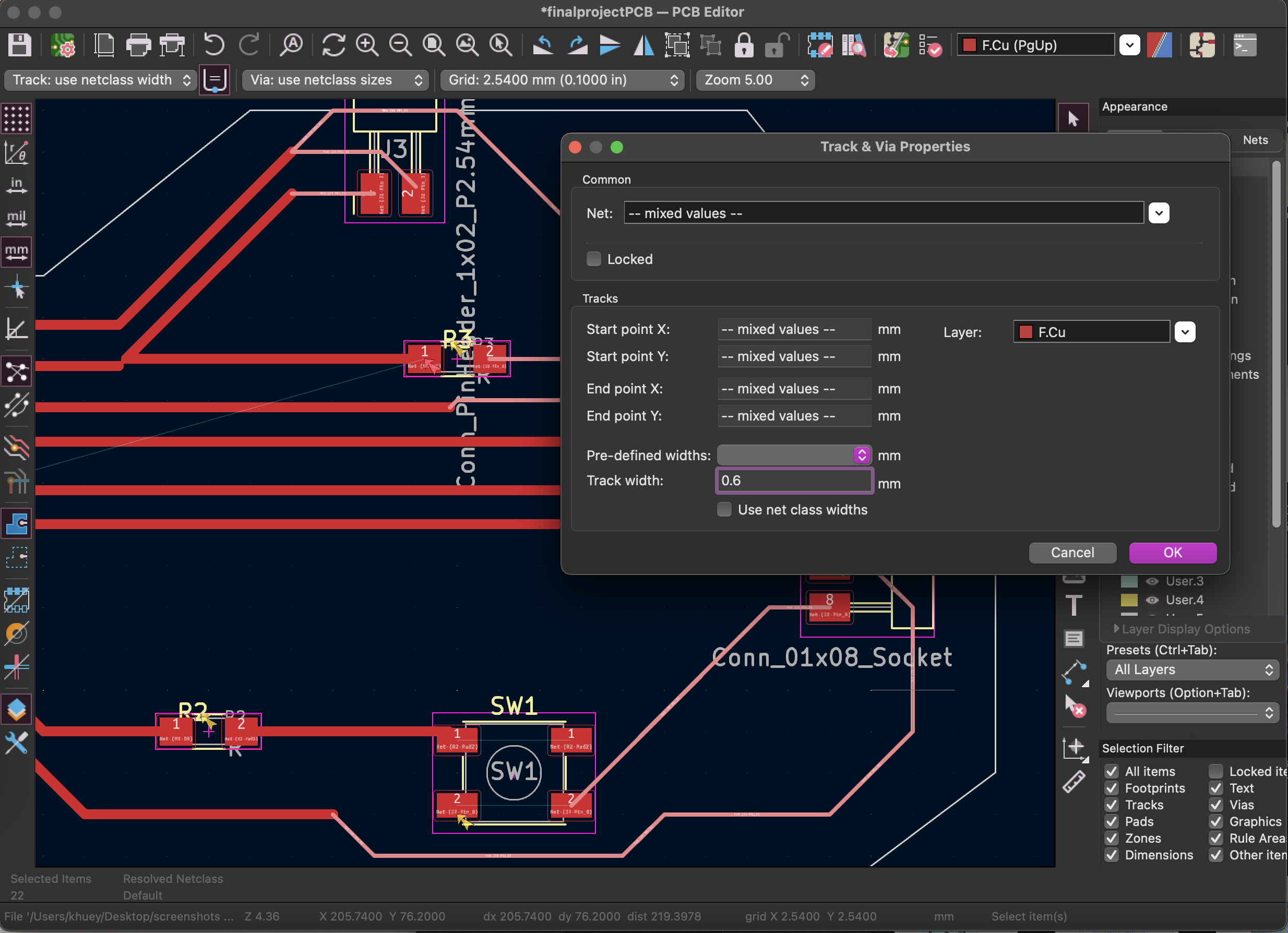
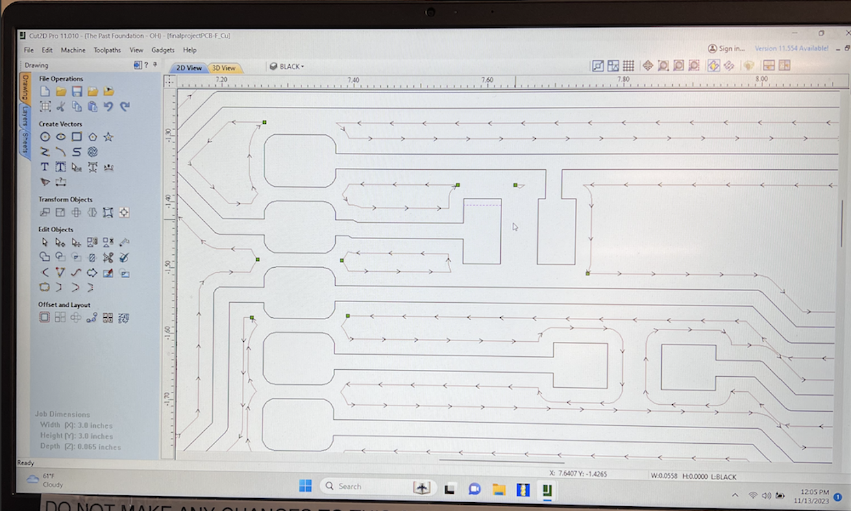
In the PCB editor, I spaced it out and placed the components where I wanted. I was unfortunate in my wiring in the schematic editor because all my wires were crossing and it made placing the tracks on the PCB editor very hard. I had to go back a few times to rearrange wires and make sure the tracks wouldn't cross over each other on my milled PCB. I finally found an arrangement that works and unfortunately when I went to mill it, it was huge. It was 4 inches long, which would have worked since I didn't have my box cut yet, but I did not want it that big. I chose to go back into Kicad and rearrange it all again, trying not to have overlapping linges but also ensuring it would have enough space in between the copper tracks to work and not short out.
Once I found the arrangement and put outlines on the Edge.Cut layer, I exported it as a DXF and took it to the Windows computer in the workshop connected to our Forest CNC Machine to mill.
Kicad Files
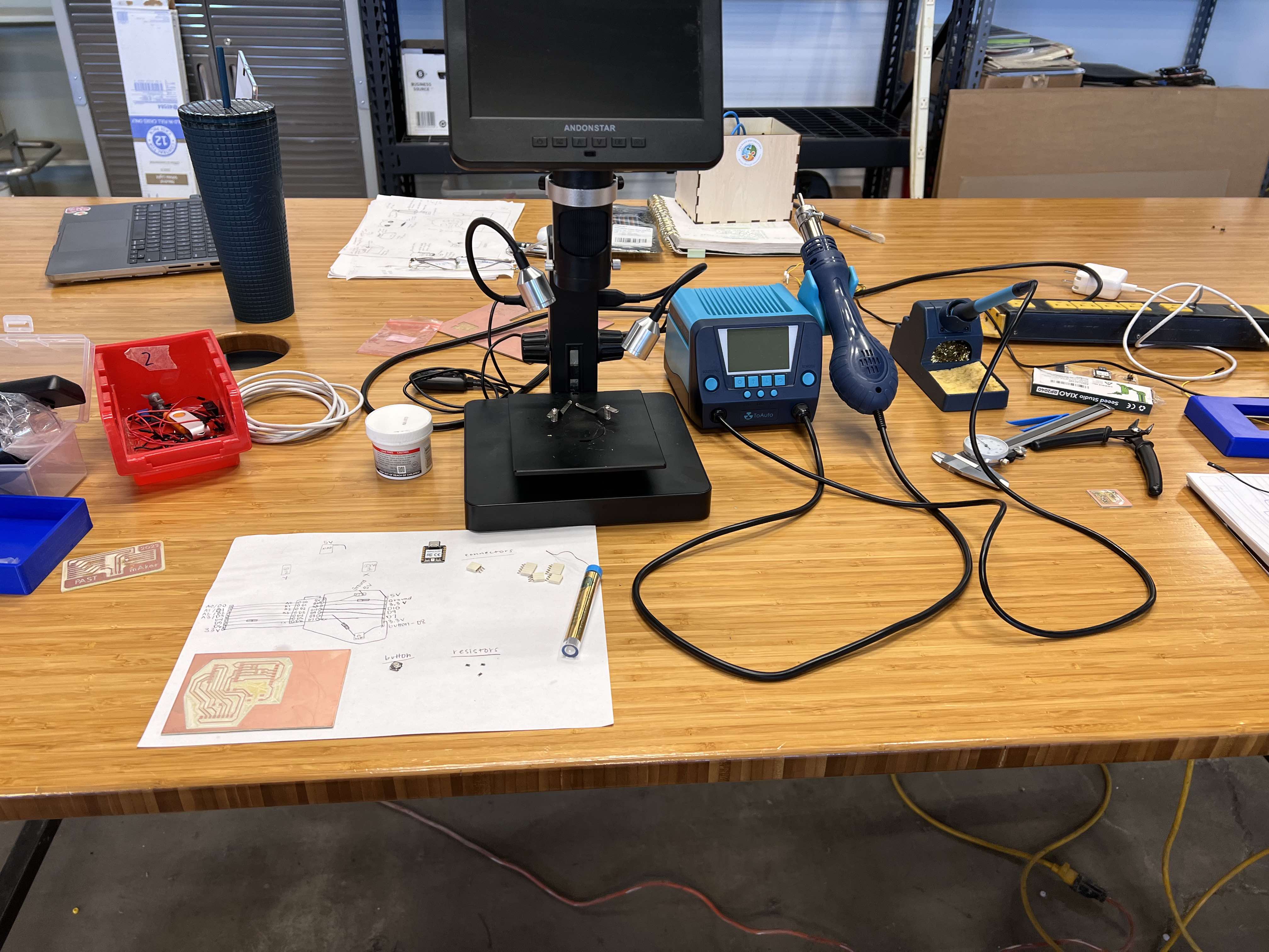
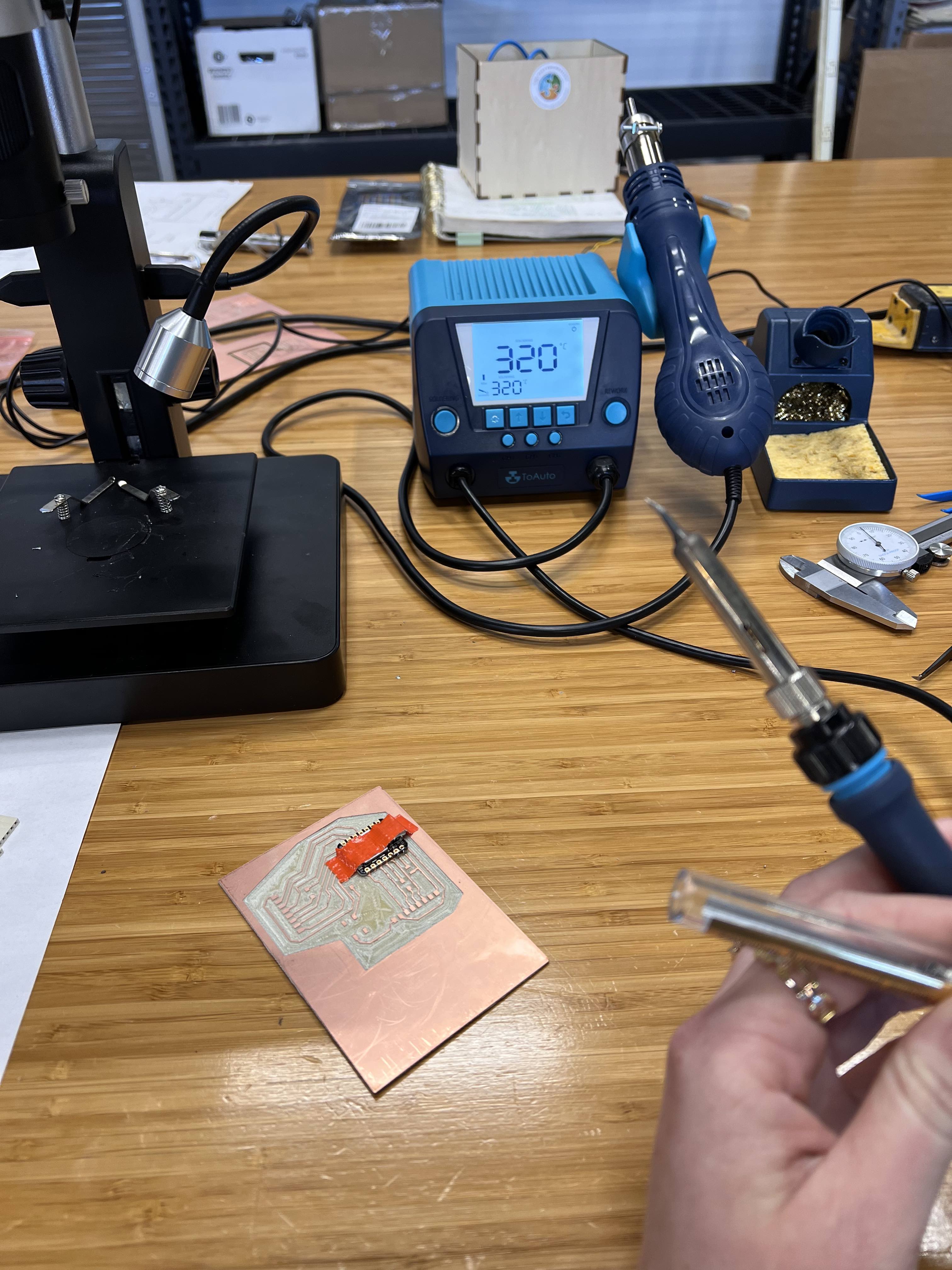
PCB Production
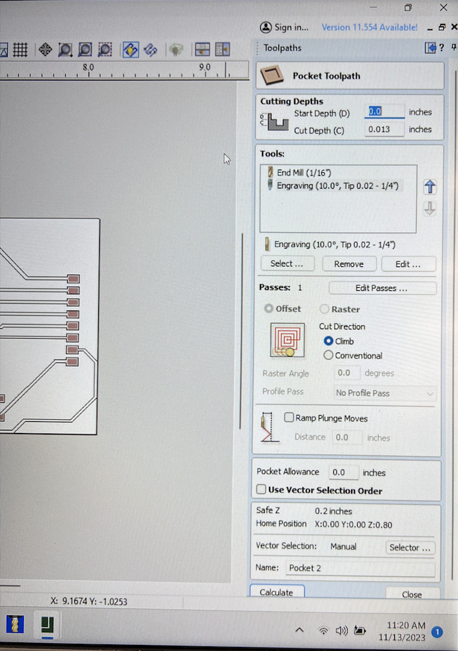
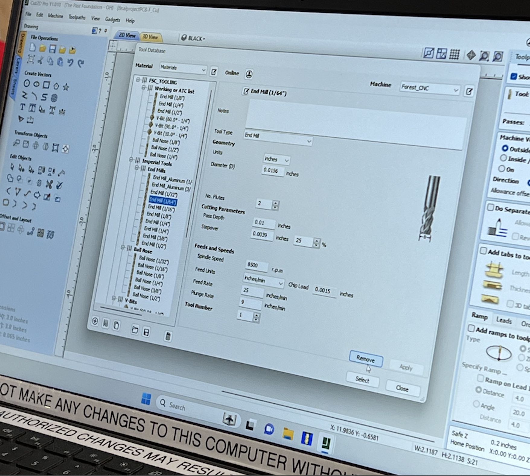
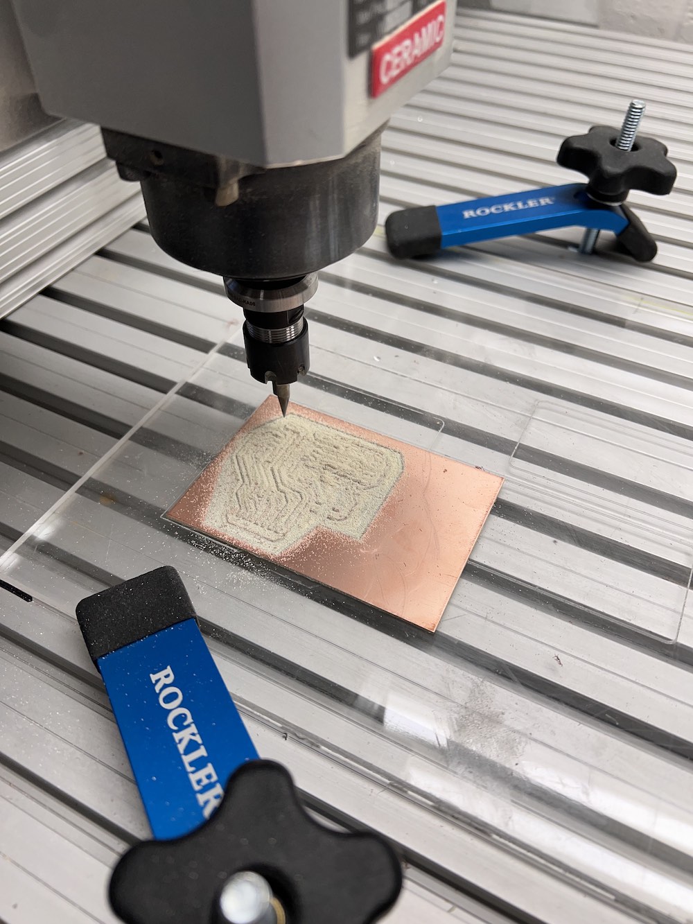
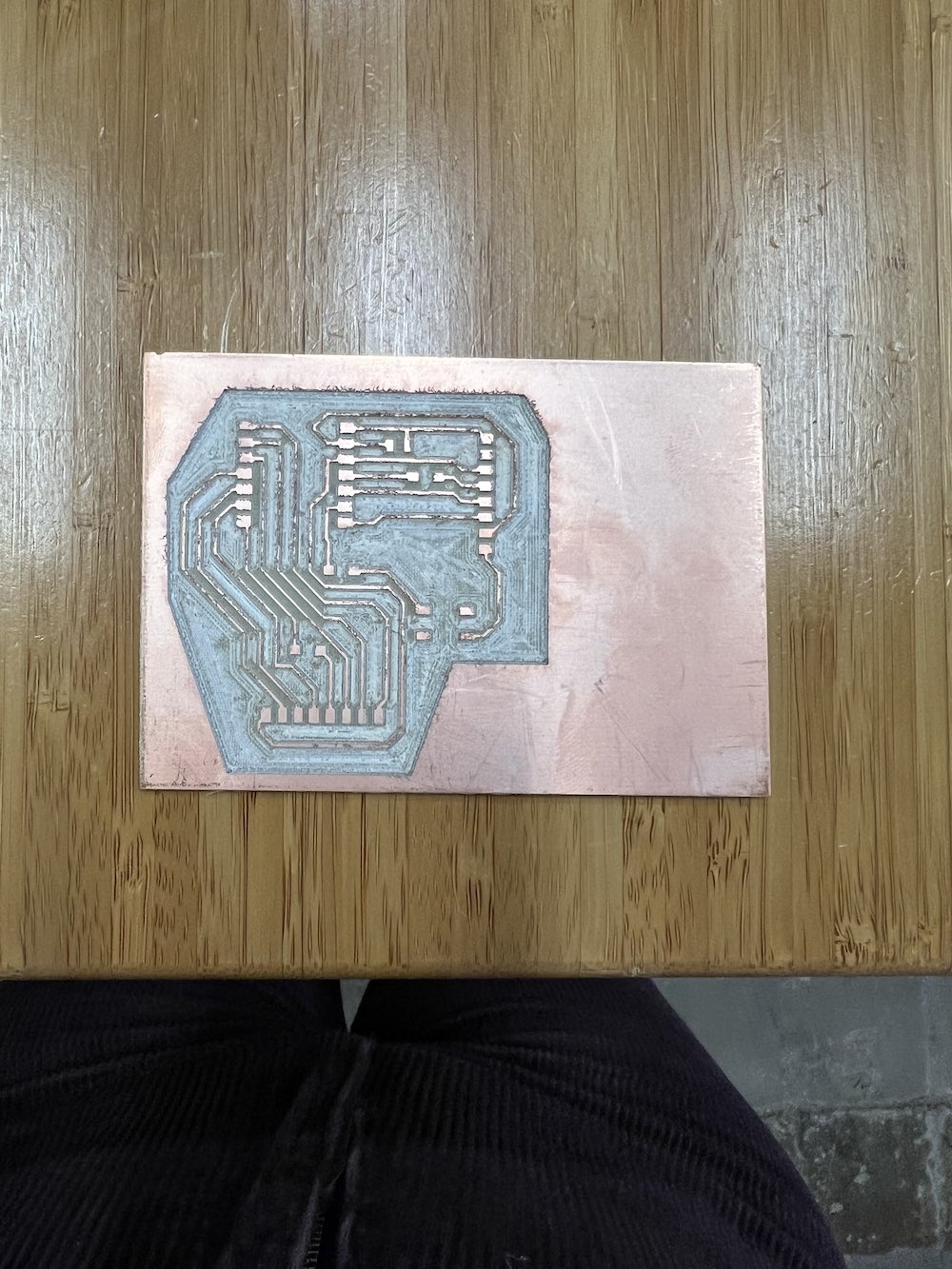
Once at the Windows laptop, I plugged the USB in thaat contained my DXF files. I imported them into Cut2D Pro and edited the pads slightly to ensure they did not overlap. I used an End Mill (1/16th) bit, then an Engraving (10.0",Tip 0.02 - 1/4") bit, followed by an End Mill (1/64").
Once it was milled, I dusted it off using a paintbrush, then got my components to solder. I set up my soldering station and aligned my components onto the PCB. Using soldering wire, the solder iron at 320 degrees, tweezers, and tape I soldered all components onto my board.
Programming my PCB - Servos ONLY
The goal of my programming is to randomly move my two servo motors in the X and Y directions. I will also have the ability to program it to do a sweeping motion back and forth to simulate a hand waving.
To do this, I am using two servo motors, my fabricated PCB with my embedded XIAO RP2040 microcontroller, wires, alligator clips, and Arduino IDE. I had been struggling to find code that I both understood, and did the necessary job for me. I tried for about a week and a half to piece together various codes and create my own but simply I did not know enough about the process to do so yet.
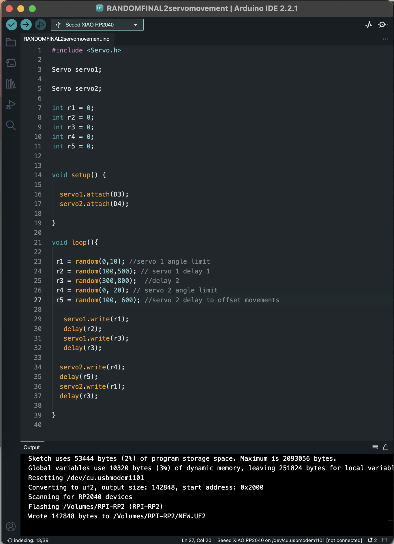
FINALLY, I found a helpful video on YouTube. This video, from Mike Theevil, called "Arduino Random servo movement Example" was perfect. He is creating an animatronic figurine with an animated tail that randomly lifts up. Using his video, and modifying the code to accomodate for both servos and my spacial parameters, I finallllllyyyy got my servos to randomly move! Yippee!! I will go over the code below, just after the wire connection information.
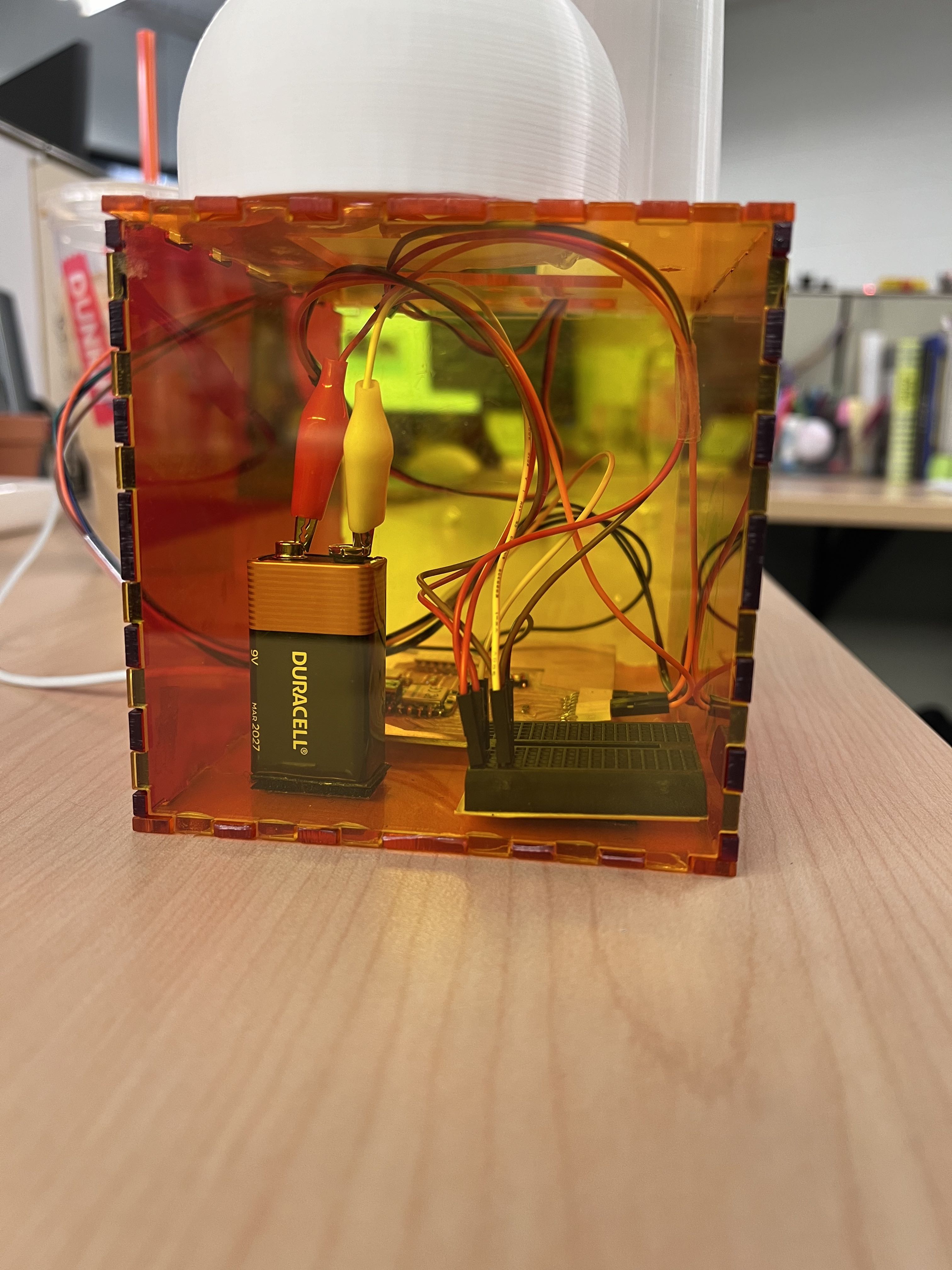
Servos have three pins, the brown is GND, red is VCC, and orange/yellow is the signal pin. I connect the signal pins of the servos to D3 and D4 of my PCB, and GND > GND and VCC > VCC on the breadboard to get the power from the battery. The battery is connected to the + and - strips of the breadboard respectively. The PCB is also connected to the ground of the breadboard through its ground pin.
       //This code is a modified version of Mike Theevil's example animatronic code. It has been modified by Kelleigh Huey to program two servos to emulate a bug in random motion.
       #include [Servo.h]

       Servo servo1; //assign servo 1

       Servo servo2; //assign servo 2

       int r1 = 0; //establishing variables
       int r2 = 0;
       int r3 = 0;
       int r4 = 0;
       int r5 = 0;


       void setup() {

         servo1.attach(D3); //attaching servos to XIAO pins
         servo2.attach(D4);

       }

       void loop(){

        r1 = random(0,10); // X servo 1 angle limit
        r2 = random(100,500); // X servo 1 delay 1
        r3 = random(300,800);  //delay 2
        r4 = random(0, 20); // Y servo 2 angle limit
        r5 = random(100, 600); // Y servo 2 delay to offset motion

          servo1.write(r1); //servo goes to random point within r1
          delay(r2);
          servo1.write(r3);
          delay(r3);

         servo2.write(r4);
         delay(r5);
         servo2.write(r1);
         delay(r3);

       }
The code above includes a library in Arduino IDE called Servo.h. Please substitute the brackets at the beginning of the code to angled brackets >. This begins the code.
Next, I assign my servo names as servo1 and servo2. servo1 is my X and servo2 is my Y. I also used the int function to create the integer value variables that will later control the angle and delay time of my servos.
Then, I assign my servos to their pins, digital pin 3 and 4 respectively. This completes my setup portion of the code.
To begin the loop code, that tells the servos what actions to take, I assign the variables to a random function. My goal is to have the laser dot behave similarly to a bug. For now, it is a very fast bug until I can figure out how to slow down the speed of my servos through steps but that's a later issue. This random function will pick a random number between the high and low value that you put. I wanted the area of the laser to be small, so my cats did not lose site of the dot and get confused, which happens sometimes if they move too quickly and they miss the transition.
I then tell the servos to go to a random position between 0 and 10 or 20 degrees (dependent on X versus Y), wait betwen 100-500 ms, then move to another position, wait, and then move again. This loop keeps the laser moving relatively quickly, but in a small enough area that my cats can follow.
Programming my PCB - Servos AND Joystick
To proceed from this success, I wanted to try to control the servos (output) using a joystick as an input device. I had previously tried this but I only had continuous servos on hand when I attempted it. The continuous servos are not compatible with the code in this project and will not function as indicated above. You need 180 degree hobby servos, or a "closed loop" servo.
I found online a few examples of code that others have gotten to work for moving servos with a joystick. Everything that I saw was above my head in terms of the code within it. I tried to read and follow all the codes and simply do not have the coding knowledge to be able to understand and modify the code they gave. Thus, I continued my pursuit in finding workable code.
Finally, I saw this website from MakerPro.com "How to Control Servo Motors With an Arduino and Joystick". I knew I was not using an Arduino board to program my PCB but knew enough to know the only real difference between coding for the arduino and for my microcontroller is the pins and making sure you attach the servos and joystick to the correct pinouts for your board.
Following the website and its instructions, I connected my PCB, servos, joystick, and battery as follows:
9V Battery:
- Positive -> breadboard strip A
- Negative -> breadboard strip B
- The breadboard I am using is a mini, which does not have a positive and negative strip running vertically /perpendicular to the majority strips. Thus, I must use a horizontal row of the breadboard to create the power and ground strips that I will connect my components to.
Servos:
- VCC -> power - strip A of breadboard
- GND -> ground - strip B of breadboard
- Signal pin -> D3 and D4 (one per servo)
Joystick:
- VCC -> power - breadboard
- GND -> ground pin on PCB
- VRx -> A0 (X axis movement)
- VRy -> A1 (Y axis movement)
PCB - you also need to connect the ground of your PCB to the ground strip you created on the breadboard, strip B.
Once the wired connection was made, I modified the code I found from the website to be the following:
           #include <Servo.h>
           Servo servo1;
           Servo servo2;
           int x_key = A0;
           int y_key = A1;
           int x_pos;
           int y_pos;
           int servo1_pin = D3;
           int servo2_pin = D4;
           int initial_position = 0;
           int initial_position1 = 0;

           void setup ( ) {
           Serial.begin (9600) ;
           servo1.attach (servo1_pin ) ;
           servo2.attach (servo2_pin ) ;
           servo1.write (initial_position);
           servo2.write (initial_position1);
           pinMode (x_key, INPUT) ;
           pinMode (y_key, INPUT) ;
           }

           void loop ( ) {
           x_pos = analogRead (x_key) ;
           y_pos = analogRead (y_key) ;

           if (x_pos < 90){
           if (initial_position < 5) { } else{ initial_position = initial_position - 5; servo1.write ( initial_position ) ; delay (600) ; } } if (x_pos > 125){
           if (initial_position > 90)
           {
           }
           else{
           initial_position = initial_position + 5;
           servo1.write ( initial_position ) ;
           delay (600) ;
           }
           }

           if (y_pos < 90){
           if (initial_position1 < 5) { } else{ initial_position1 = initial_position1 - 5; servo2.write ( initial_position1 ) ; delay (600) ; } } if (y_pos > 125){
           if (initial_position1 > 90)
           {
           }
           else{
           initial_position1 = initial_position1 + 5;
           servo2.write ( initial_position1 ) ;
           delay (600) ;
           }
           }
           }
Below is an image that explains each chunk of code and what it does for my project.
Putting it all together
I am using my PCB with the XIAO RP2040 microcontroller, wires, a 9V battery, and a mini breadboard to make the necessary connections and power my servos. I am using a joystick as an input to control the output which is my servos. Wiring information can be found above in my "Programming my PCB - Servo AND Joystick" section.
The box was simple to put together, I collect all the pieces I need (front, back, left, right, top and bottom) and get them organized in front of me. I start with the bottom and add the left and back side pieces. Next, I add the right side and front piece. Last, I put the top... right on top! I did end up using a small amount of hot glue on the corners of the box, just in case the vibration of the servos knocks the box loose, I don't want my toy to fall apart.
The hole in the back of my box will allow the power cord to the XIAO board to connect with my computer. This hole also has my joystick and its wire so the user can control the servos with the joystick. The hole in the top and through the arm of the cat will allow the servo wires to pass through and connect to my board.
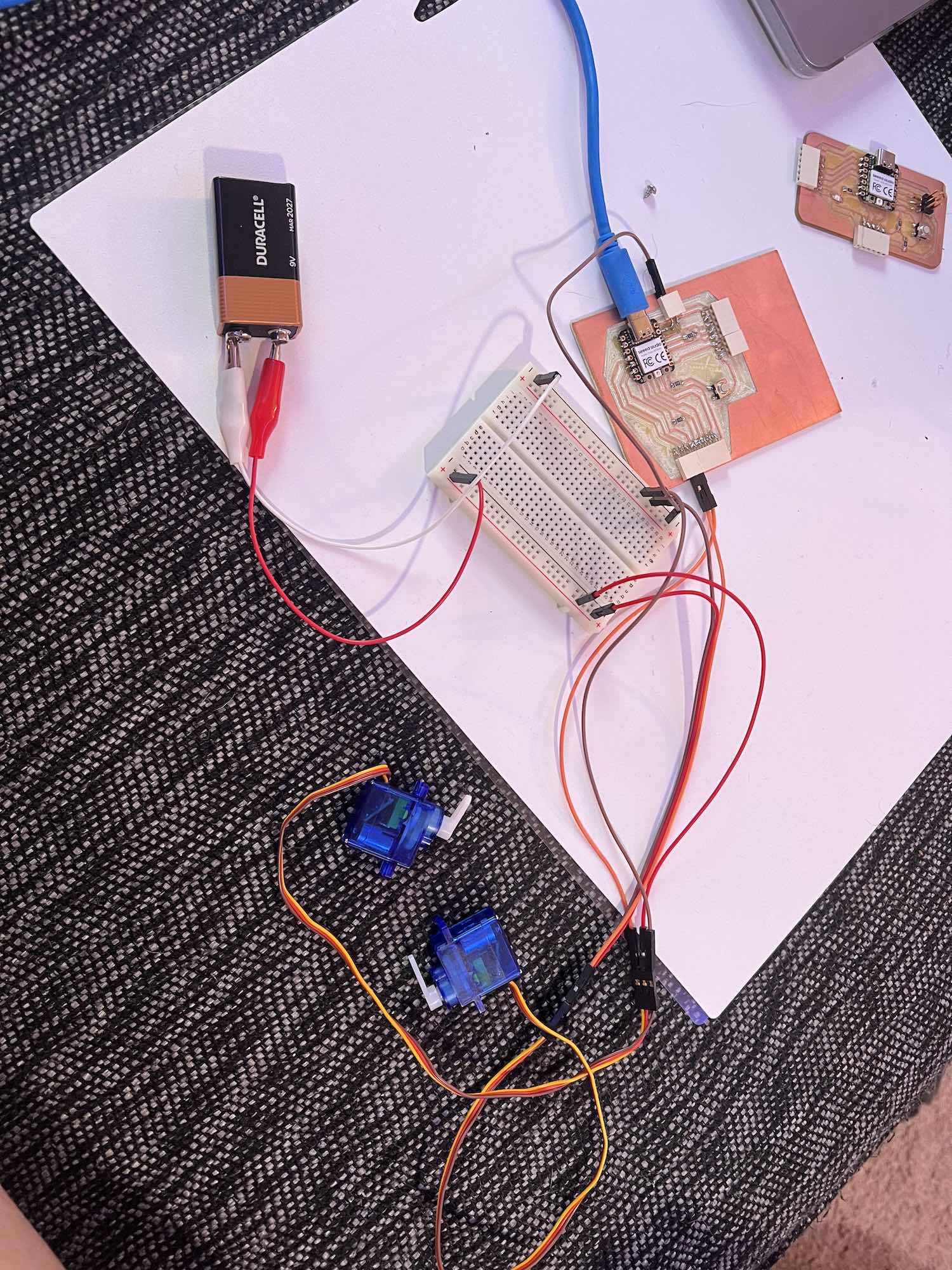
This is from when I was testing code to make sure the servos would work for the job I am giving them.
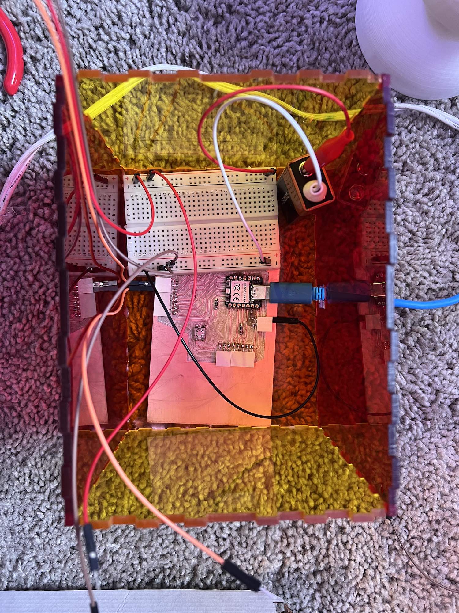
This is the final wiring of the toy when it was just the two servos, battery, breadboard, and my PCB.
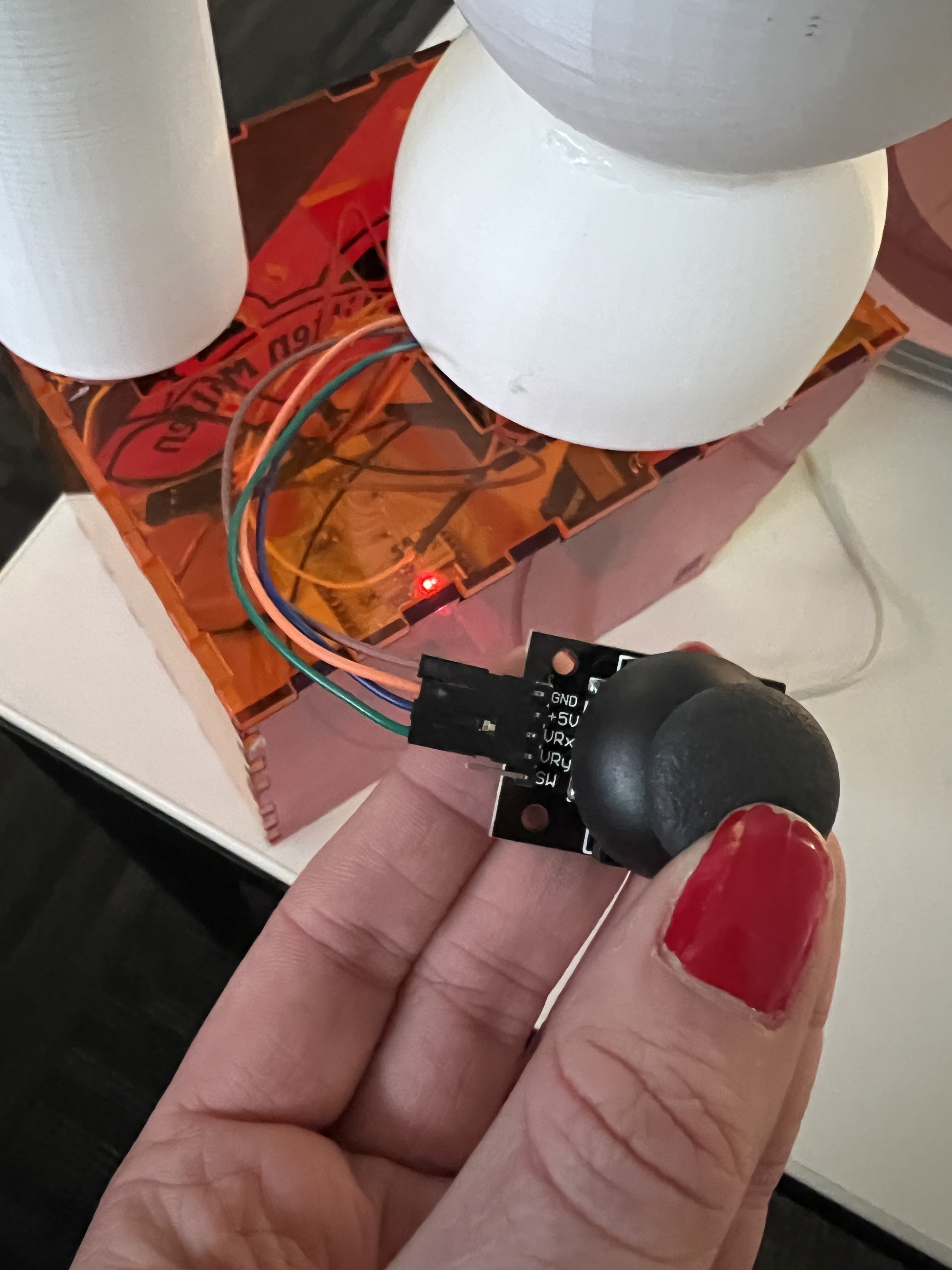
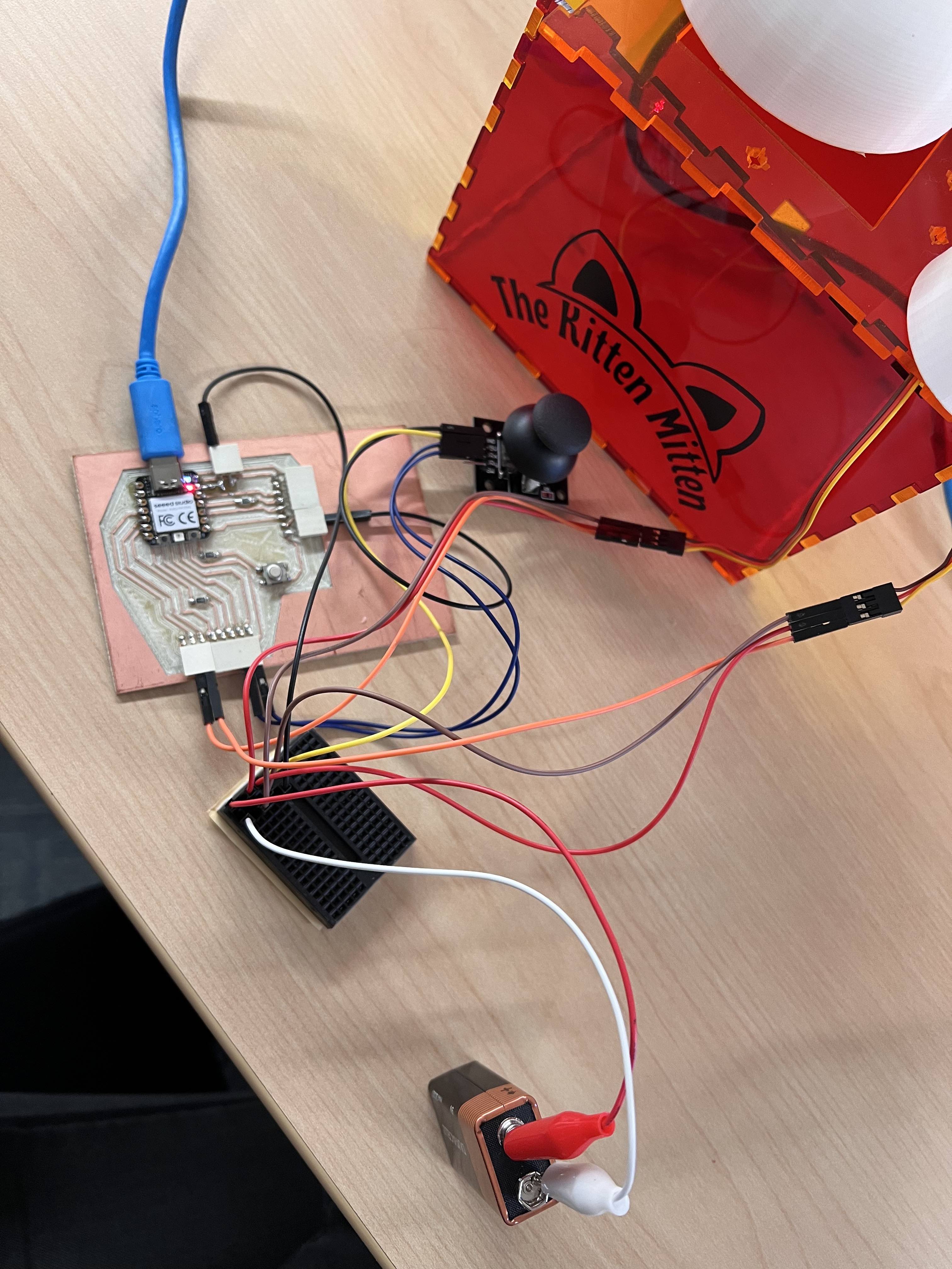
This is showing the wiring from when I was testing the functionality of the joystick with my servos. The first image is the pins on my joystick.
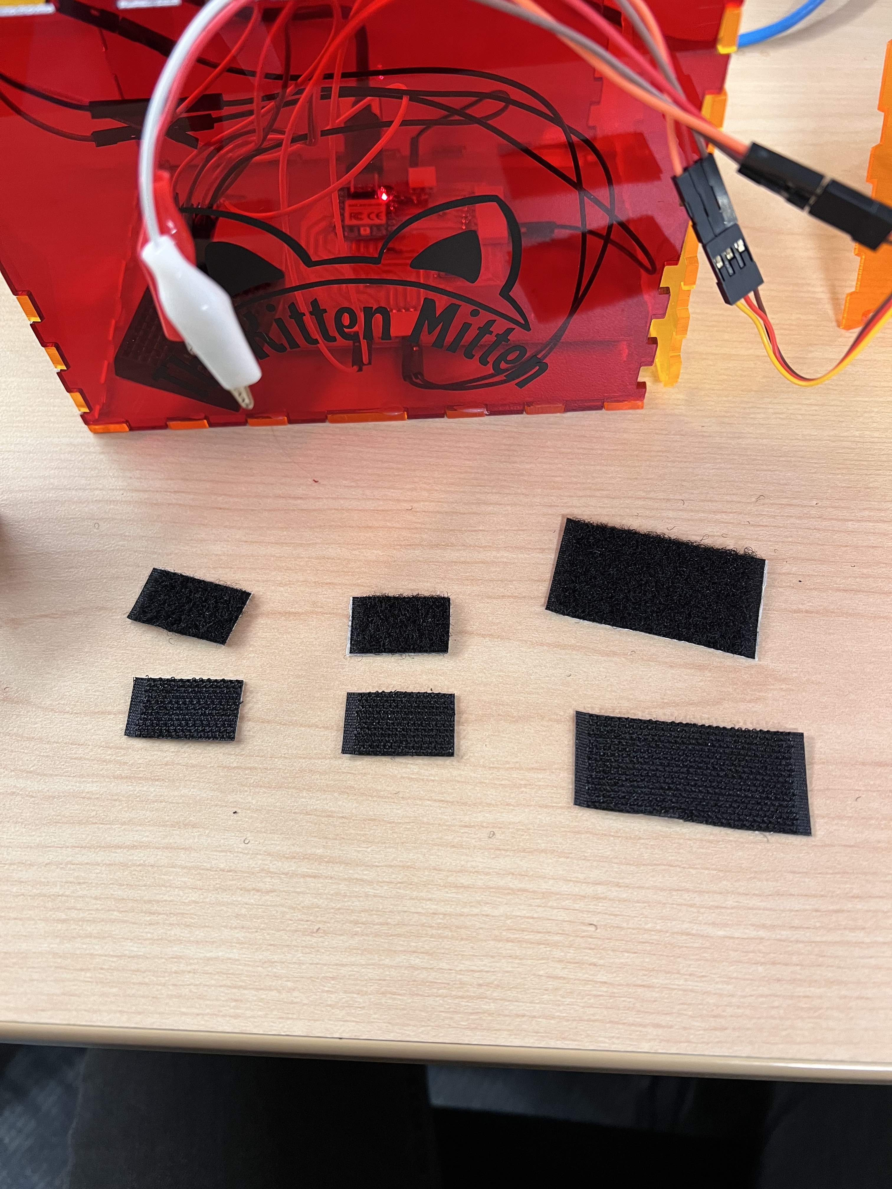
I decided to use velcro strips on the botton of my battery, breadboard, and PCB to ensure the electronics would not slide around. This just adds stability.
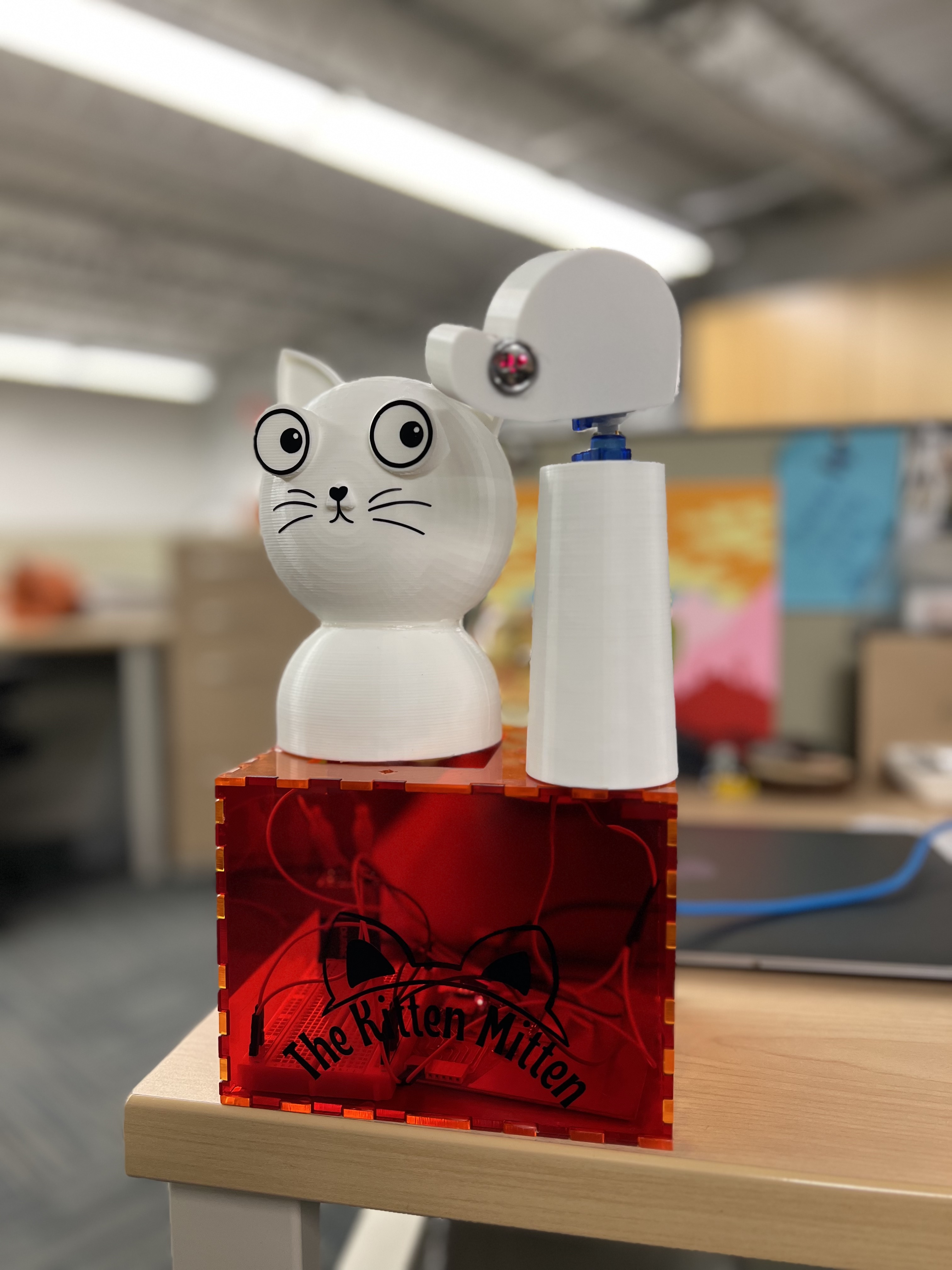
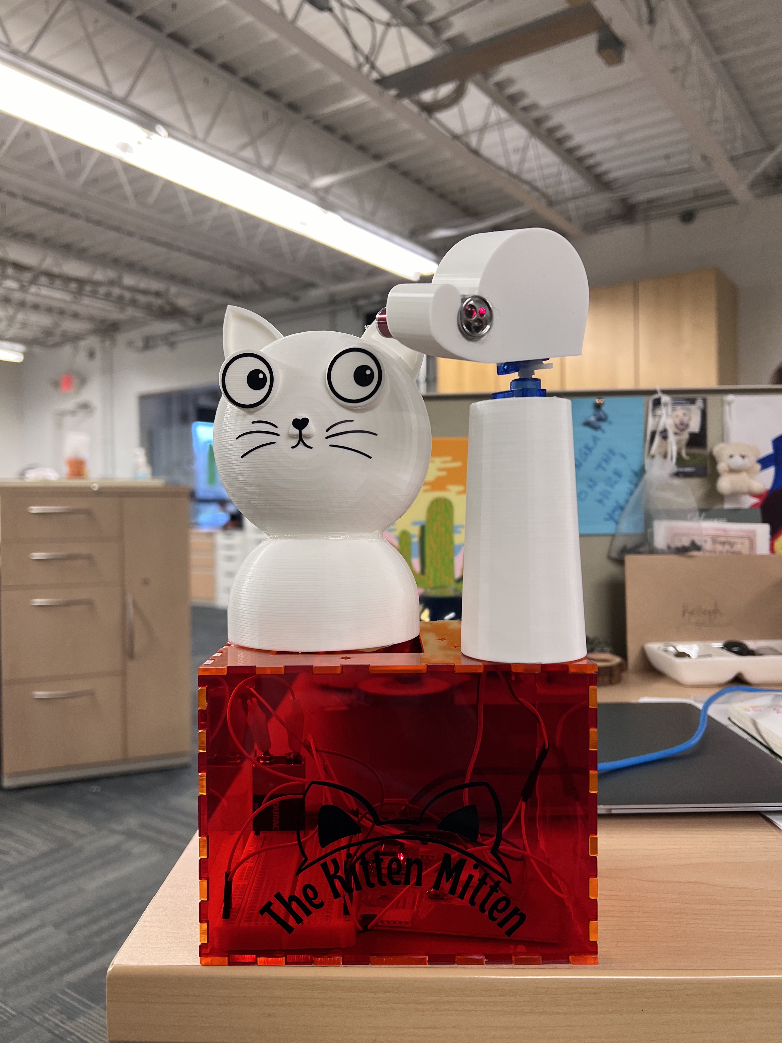
The two images above depict my final wiring of my electronics and putting it together in the box I created. Next, it is to add the finishing touches, the kitty face and the logo for my box!
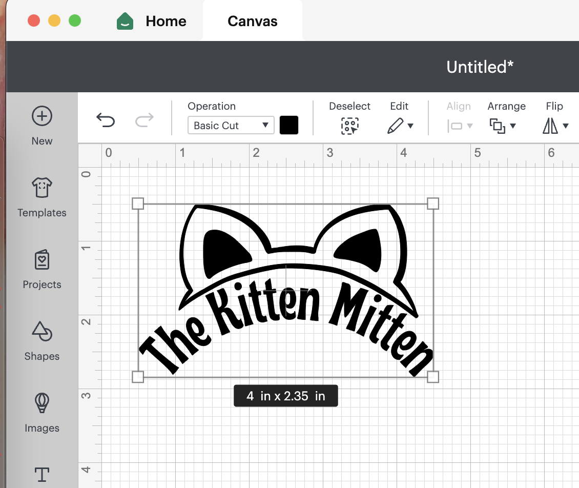
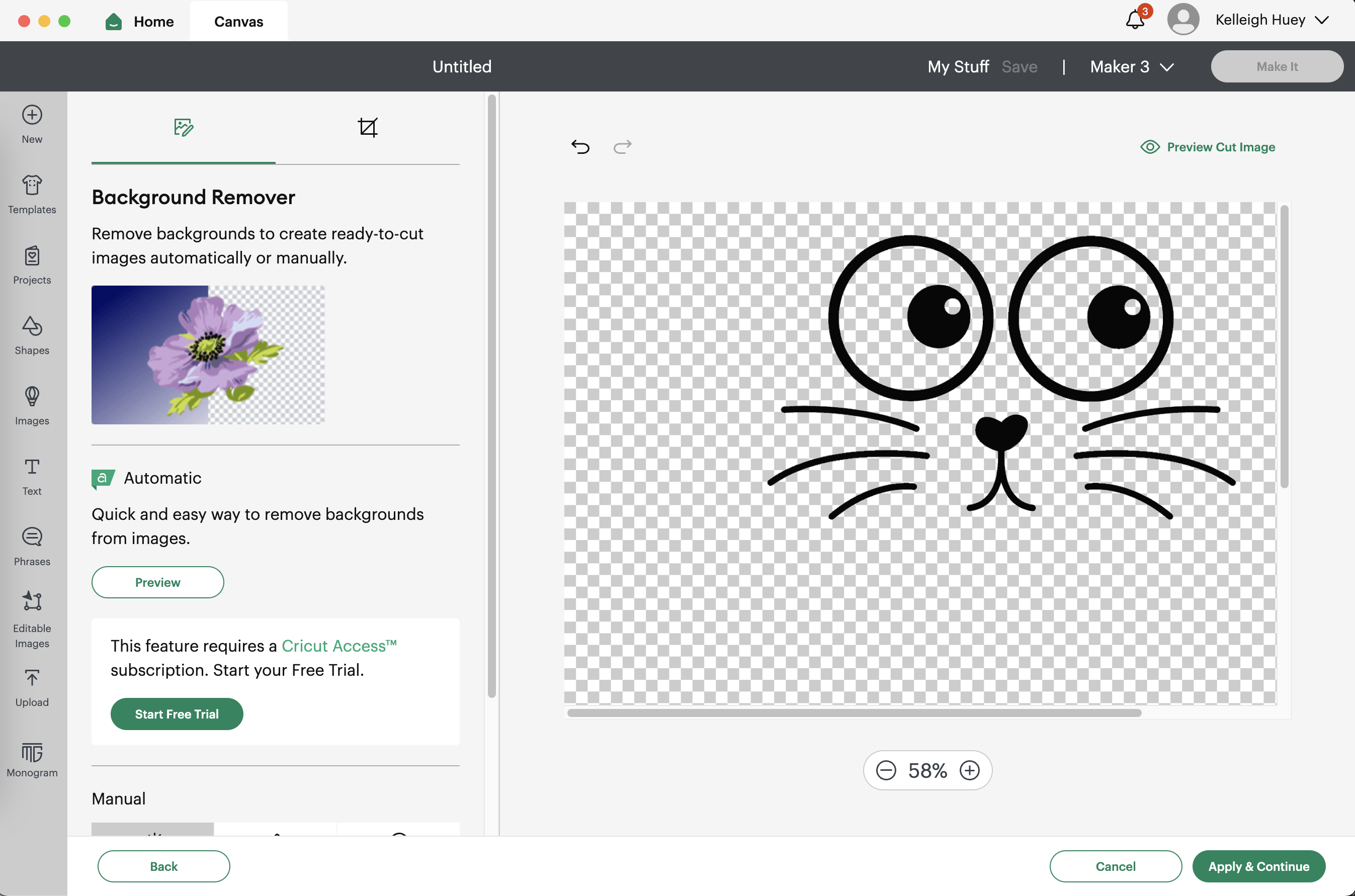
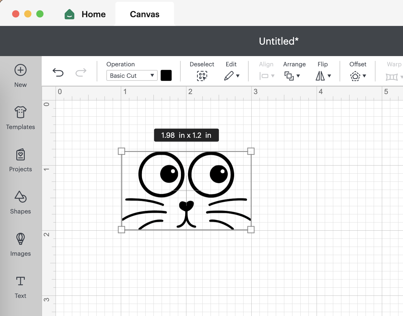
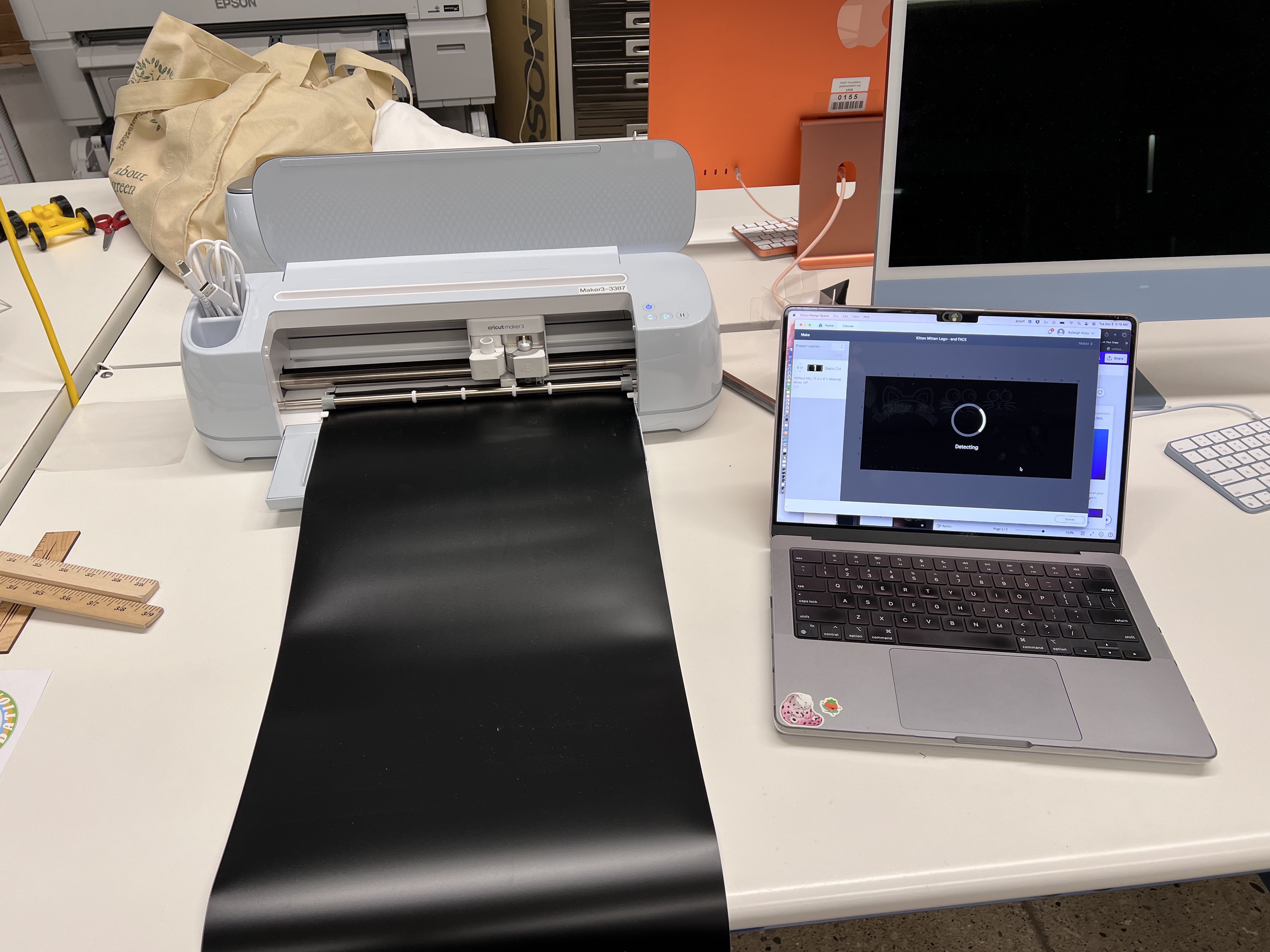
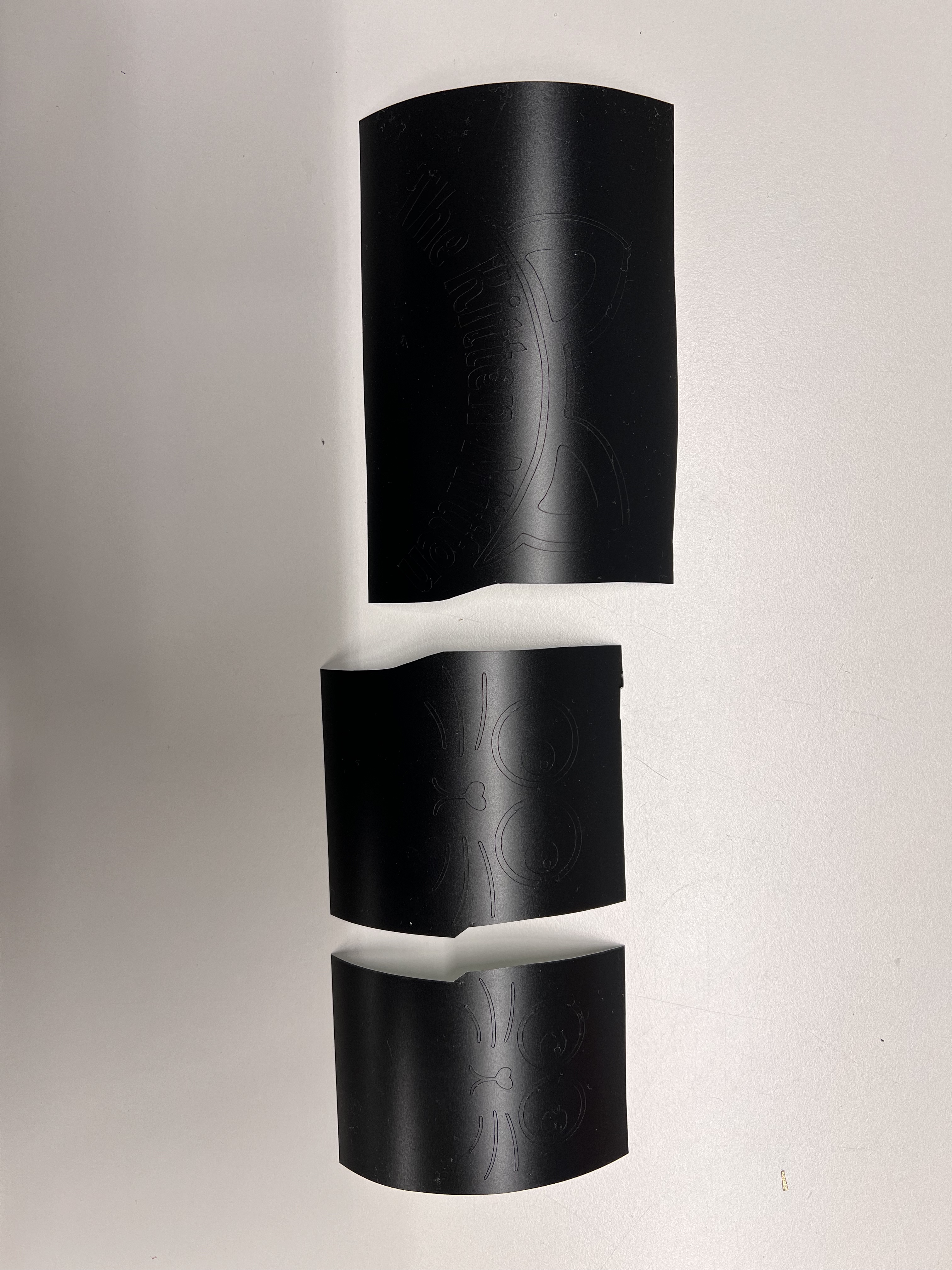
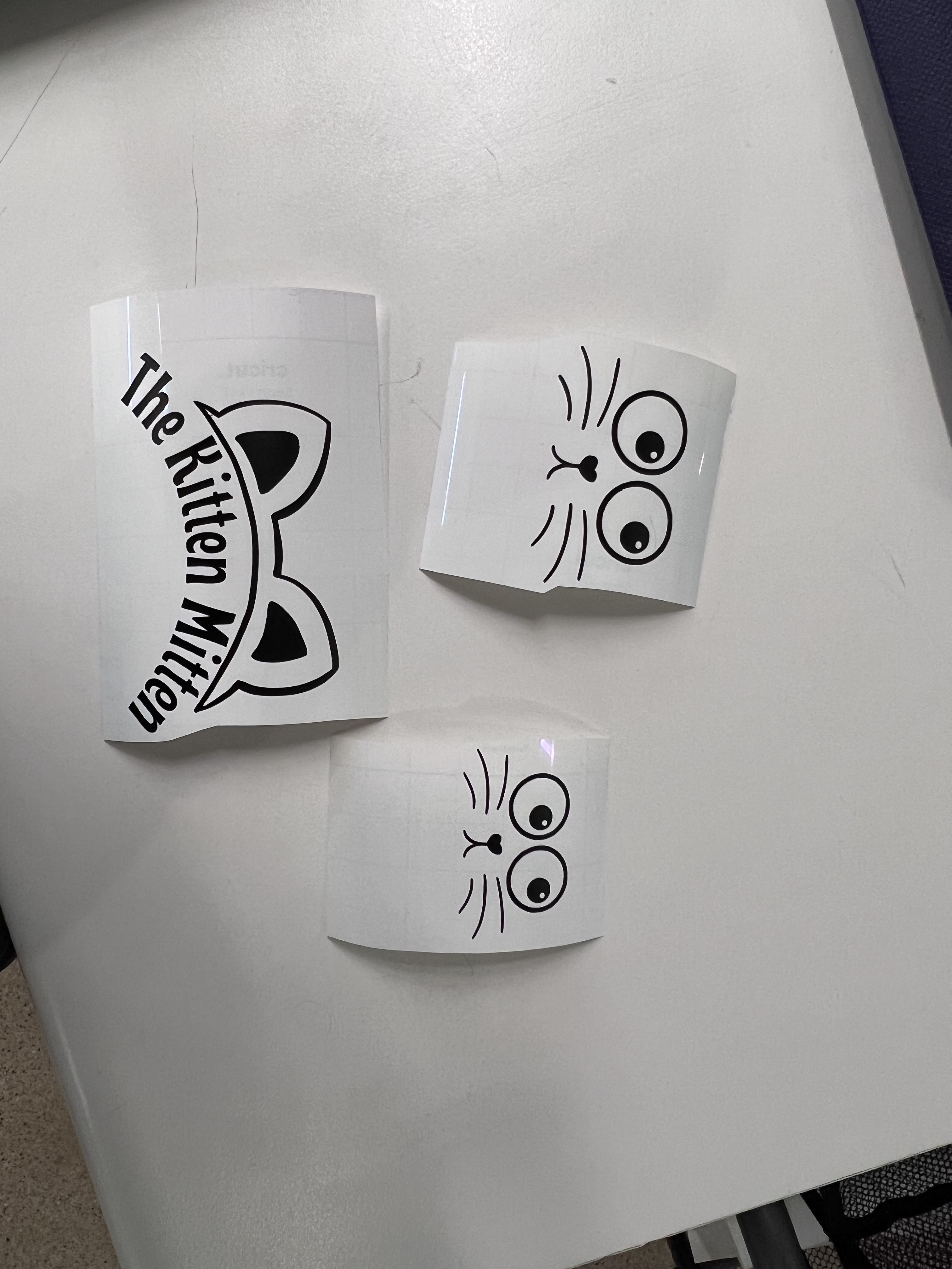
Vinyl Cutting
The vinyl cutting I did was on the Cricut Maker 3. I would like to use it to create different facial features or various prints that can go on my cat toy. It will add to the aesthetics of the project, making it pleasing to look at while it sits at rest on my desk. I will also add the toy name to the box. More information can be found on my week 3 - Computer Controlled Cutting

Vinyl Cut Files
A nice feature of the Cricut design space is the ability to upload any .png, .jpg, .gif, .svg, .dxf, .heic, or .bmp file and you have the ability to adjust how it uploads. By that I mean, you can selectively remove the background, select if you are going to print the image or cut it only, etc. which gives flexibility in what you make. Because I am using the Cricut Maker 3 in my office, it only has the ability to cut at the moment. We do not have the pen attachment to allow it to draw then cut.
Simply download these images, upload them to the design space, then make it! It seems too easy but it really is. I love using the Cricut and its application. The interface is super user friendly in my opinion.
Final Slide
I used Canva to create my final slide for my project. Canva is a super easy platform to use, and the free version has a lot of tools and applications you can use. I highly recommend using Canva for any 2D marketing/designing! I uploaded my photos, added a background and some text, and it was that simple!
Final Video
I used Biteable to create the final video for my project.
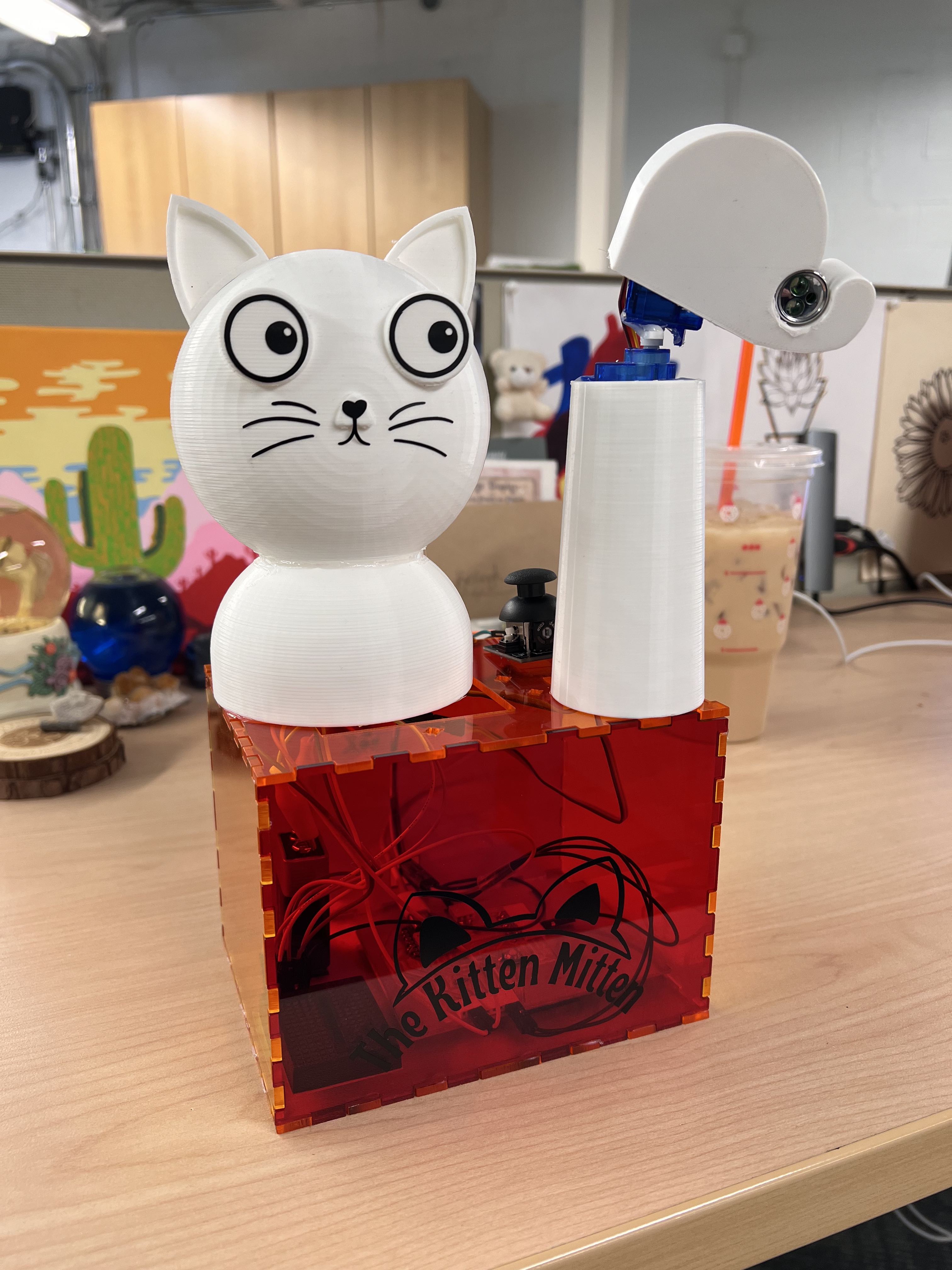
The Kitten Mitten Complete and in Use!
So far, my kittens have enjoyed playing with the laser toy so far. It could definitely still use adjustments but I am proud of how it turned out! The three videos below are using the random code function with just the servos as outputs.
Below, you will see video of the Kitten Mitten working with the Joystick. The joystick module with the servos causes a jittery movement, which I honestly think I like better than the movement you get with just the servos.
The joystick code I put in causes the servo to take small steps (5 degree increments) towards the direction of the joystick BUT remember the servos can only move in the positive direction, so we are mainly dealing with one side of the joystick at a time for each servo. Once the joystick is released, it takes 5 degree steps back towards the initial position.
The motion it creates is similar to a grasshopper which makes me really excited - my kittens love bugs. By far their favorite bug they have encountered is a grasshopper. They've seen 2 grasshoppers before and I kid you not, they followed it and entertained themselves for like 5-10 minutes alone with just this bug... I can't get them to pay attention for longer than 30 second so it really was crazy how focused they were on the bug.
Anyways, I am excited that I have completed this project and am very hopeful that my kitties will enjoy this for a long time.
What I learned in boating school is.....
I hope someone laughs at that Spongebob reference. But really, I learned a TON of new things while in this course, not only about the topics they taught us but I also learned a lot about myself and my abilities. I really doubted myself before starting this course... I had 0 experience in electronics (besides a basic college physics course), 0 experience in CAD and digital fabrication, and 0 experience in coding.
I now feel super comfortable in almost every single category/topic we learned about. I definitely still have more to learn, especially about electronics. I feel like you can never know enough about these topics, theres always more to find out and discover.
I think the most growth was shown in my electronics knowledge. I am now able to design a PCB board depending on the inputs, outputs, power consumption, etc. that is necessary for the project you desire to make. I can definitely still learn more in every category, especially electronics, considering there are sooo many different components you can use and they all require slightly different conditions.
I think I am most excited about the fact that I can make just about anything now and I feel confident in doing so.