Output Devices
This week, we discussed output devices. An output device is any component which converts information from the microcontroller to a perceivable form by humans.
Group Assignment
The general group assignment page can be found here.
We are housing our group assignment information on Nikki Stancampiano's Week 9 - Output Devices page. She will have the full example and explanation of how to read current drawn from a servo motor. I will be giving my shortened version below.
The assignment was the following:
- measure the power consumption of an output device
Power
[pre-reading note: this ended up being the incorrect way of measuring] The power in an electrical circuit is a measure of how much work can be done in a certain amount of time. This can be measured with a multimeter. The formula for power is P=I*V . Power (P) is measured in watts, voltage (V) is measured in volts, and current (I) is measured in amps.
We used a multimeter to test the power consumption of our output device, the servo motor. To do this, we touched the black wire of the multimeter (ground) to the ground pin of the board, and touched the red wire probe to the pin with the servo attached. Our reading was pretty consistent around 3.29 V.
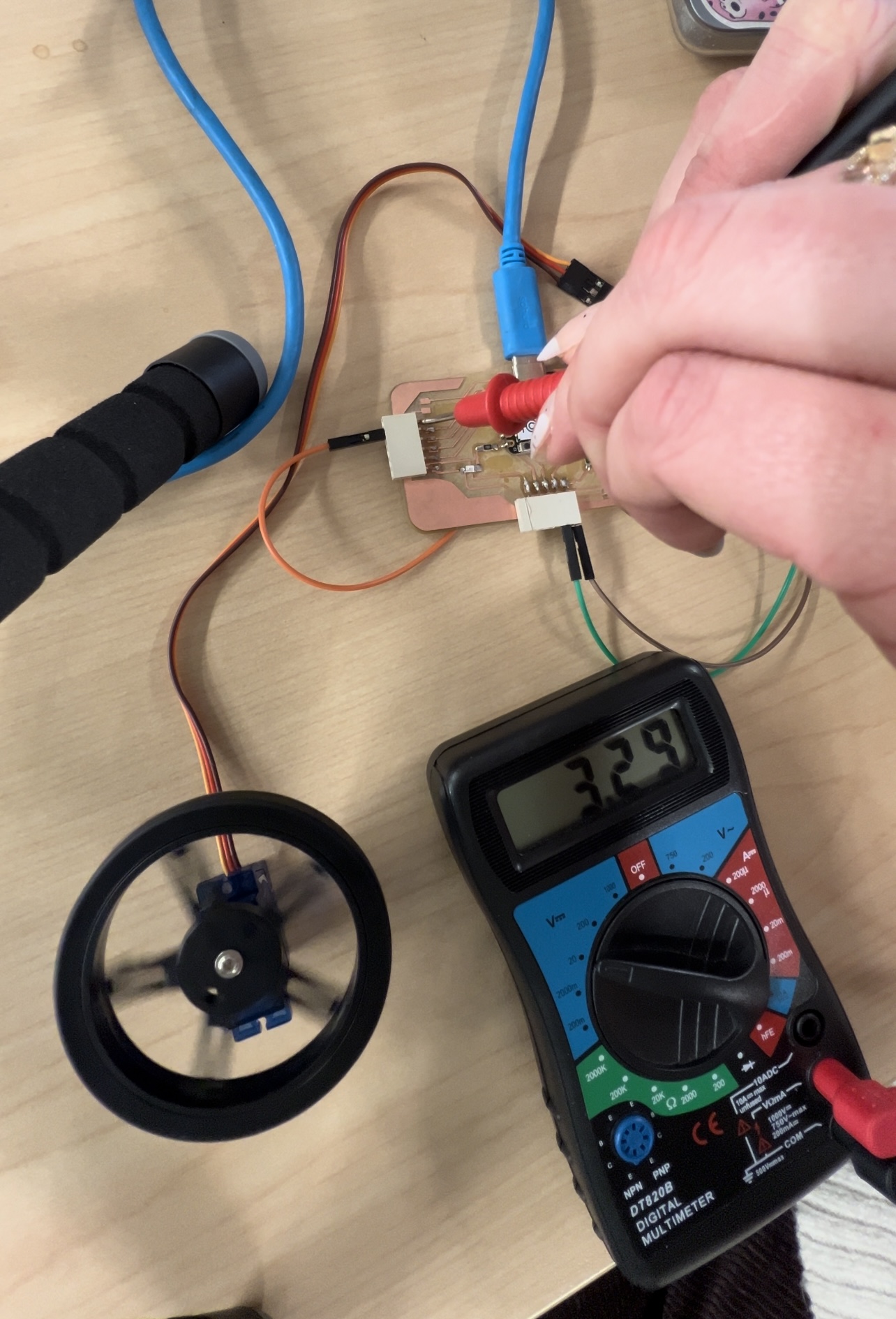
Above is not the correct way of doing this and I was unaware of that fact before now... Scratch that. I want to keep it on my page as a reminder that everyone is a lifelong learner and there are always modifications and failures and successes and life moves on regardless.
Summary of the Group Assignment
At the moment, our group is split up, all at our own homes so we are working together remotely to complete this group assignment. We have been messaging and sending pictures and videos to each other asking for help but we finally got a good understanding of what we are being asked to do and we were able to complete the assignment from home. Yay!
To start, I gathered my materials. I used a breadboard, a 9V battery, a multimeter, a continuous rotation servo, a custom PCB with my XIAO RP2040 on it, wires, and a laptop. I used my phone to record the video, the perspective is a bit wonky due to being alone while trying to complete this.
PCB/microcontroller Connections: Connect to laptop through USB-C. Connect GND to negative strip on breadboard.
Servo Connections: Connect GND to negative strip on breadboard. Connect signal pin to A0 on microcontroller. Connect VCC to positive strip on breadboard.
Battery Connections: Connect NEG to negative strip on breadboard. Leave POS (+) open for now.
Multimeter Connections: To finish the circuit, you will touch/connect the red (positive) probe of the multimeter to the positive terminal of the battery. The black (negative) probe will connect to the breadboard, between the servo and the battery.
The way you connect your circuit will definitely affect the performance. You need to treat the multimeter as part of the circuit, like one big long, open loop. It is not an external loop attached to an already closed loop. You must break the original loop and insert the multimeter in the correct direction of current flow. Positive probe on the closest side to the positive battery terminal, and negative probe closest to the servo.
My flow in this circuit is basically from battery, through multimeter, to servo, to breadboard, back to battery (simplified).
When using your multimeter make sure you use the correct port for your red probe. It must be in the A port, to be able to read current.
These are the videos I took while measuring the current drawn from the continuous servo. I got a reading of about 2.7 mA.
Some useful resources for helping me were,
- Arduino - Multimeter Basics
- Josh Gibson - Checking Amp Drawn on an RC Servo
- Arduino - Sweep Code for Servo Motor
Individual Assignment
Our individual assignment this week was the following:
- add an output device to a microcontroller board you've designed and program it to do something.
This means I needed to begin with designing the circuit board, which we learned in week 6, electronics design. I also need to use this design and produce it for our electronics production week (week 8), and I need to use use knowledge from week 4, embedded programming of my microcontroller. I will go very briefly over those weeks before I dive deeper into the process of my individual assignment for the week, output devices.
Week 6 - Electronics Design Images
You can find the link to my week 6 assignment here.
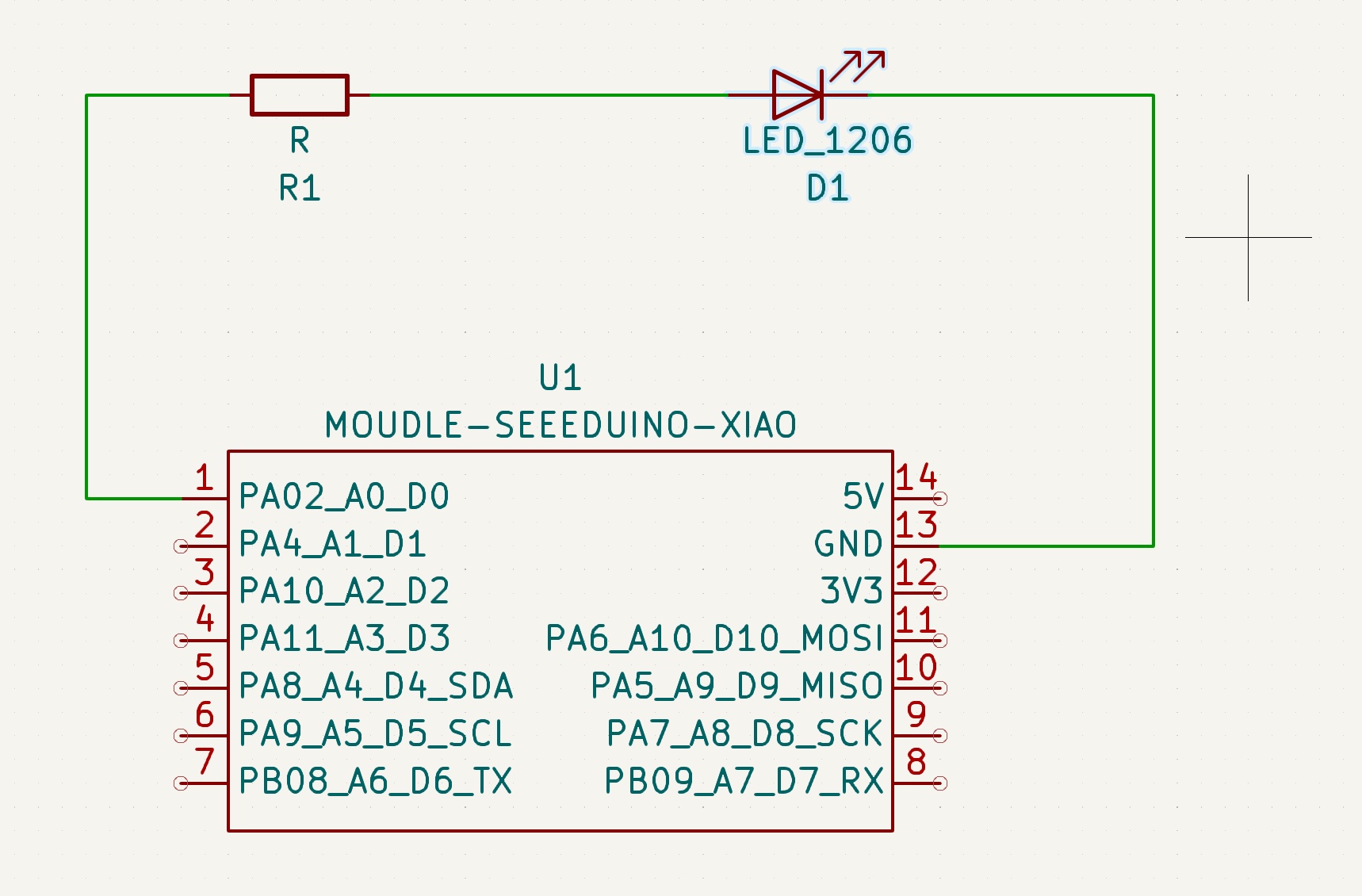
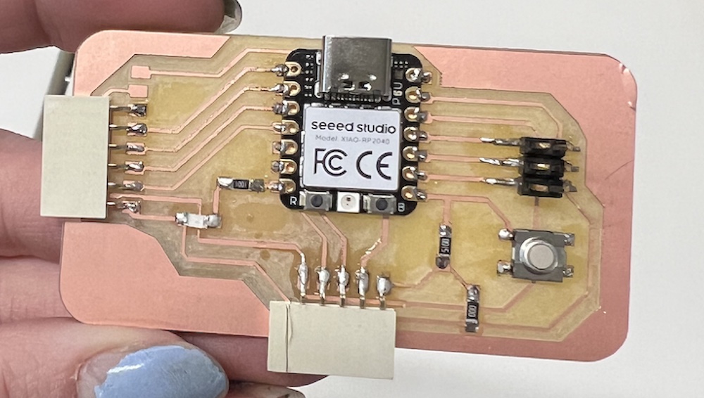
This is the schematic design of my very simple board (iteration #1). The pin is connected to the resistor, which is then connected to my LED, which connects back to GND to form the circuit. I am unsure if this connection is the proper order. I also believe to pass the Electrical Rules Checker in Kicad I needed to add a "no-connection flag" to each pin that remains unconnected.
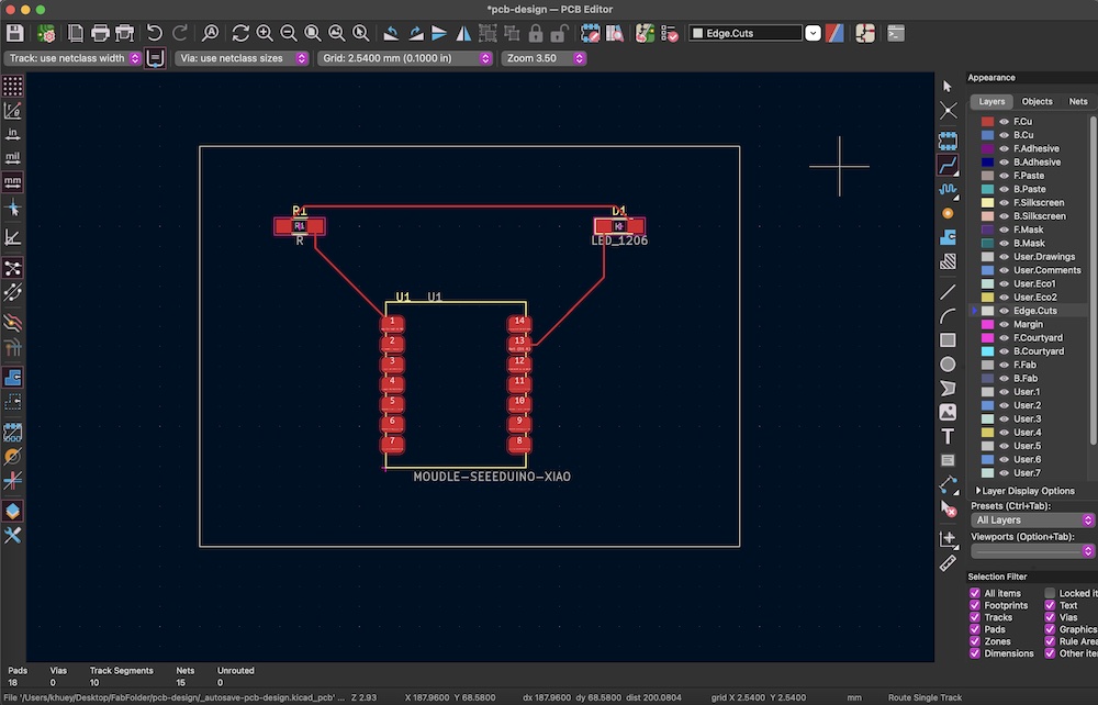
This is the PCB editor in Kicad. I updated it from my schematic page, rearranged my components, and added an edge cut on that specific layer, then routed tracks to and from each component.
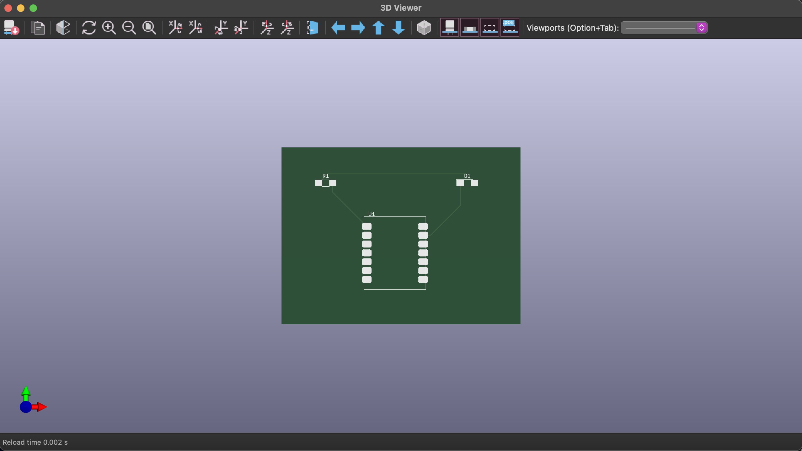
This is the 3D Viewer feature in Kicad. This is what my design would look like when it is completed.
Week 8 - Electronics Production and Images
The production of our electronics was our week 8. Our group struggled with this particular week because we were running into error after error. I discuss this more in my electronics production weeks' page. Eventually, after what seemed like a million and two trials on the Modela MDX-50, we tried the older, but still functional Forest CNC machine. This machine functions in the same way and can have the same capabilities if the tools are swapped out properly.
You can find the link to my week 8 assignment here.
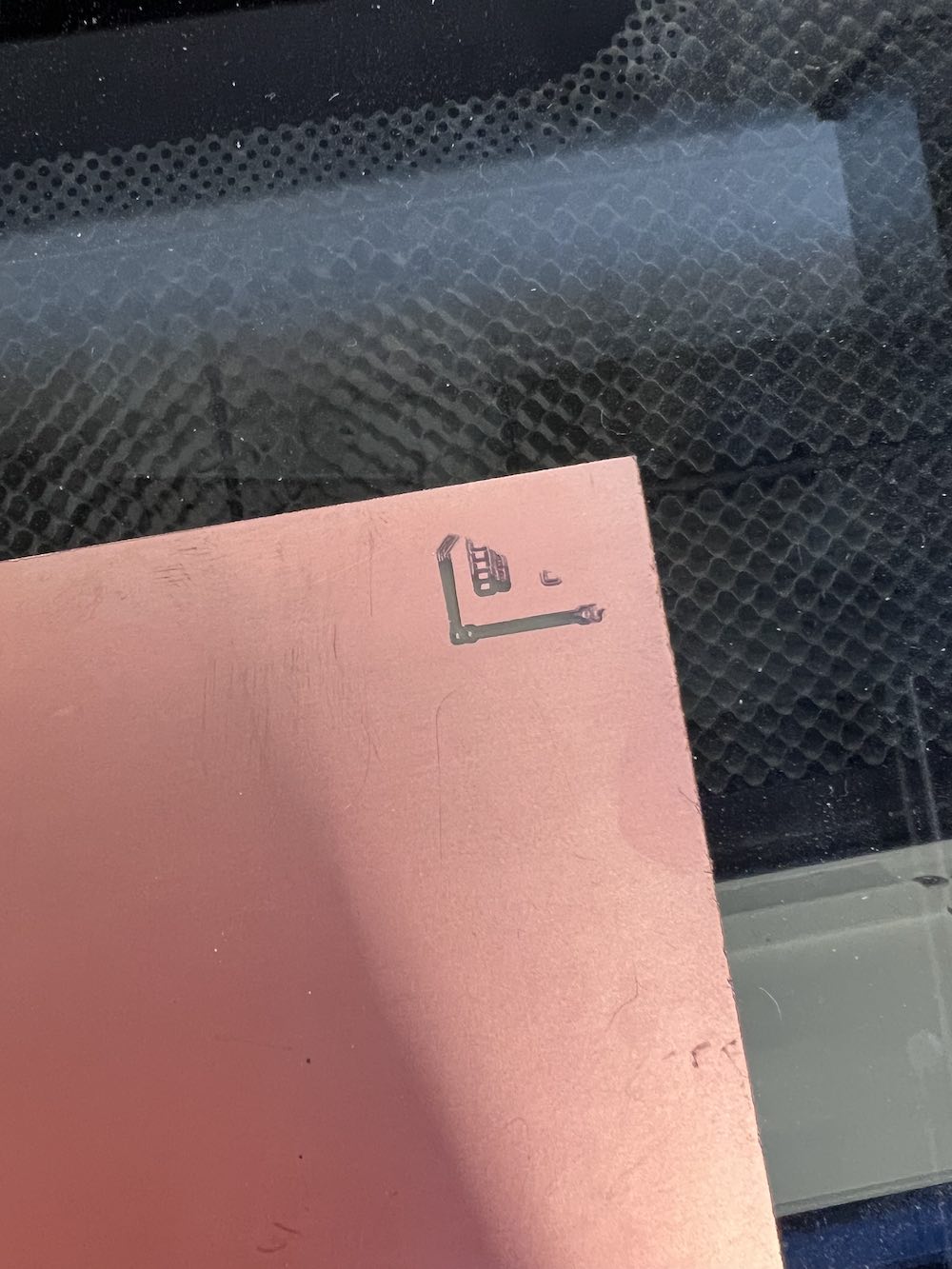
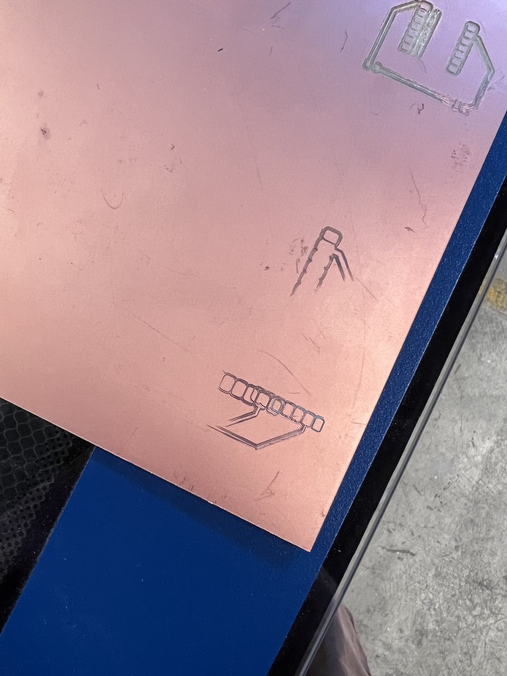
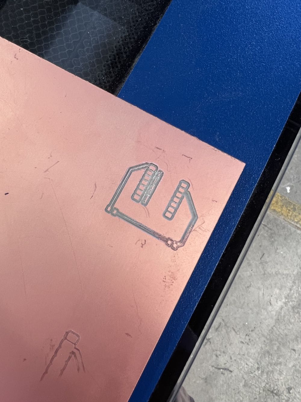
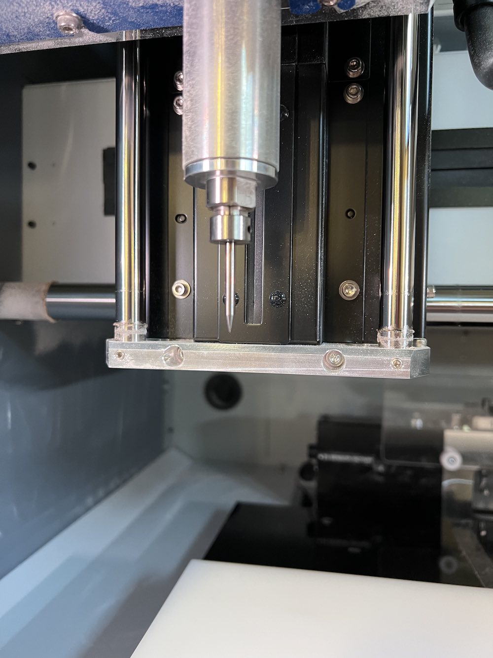
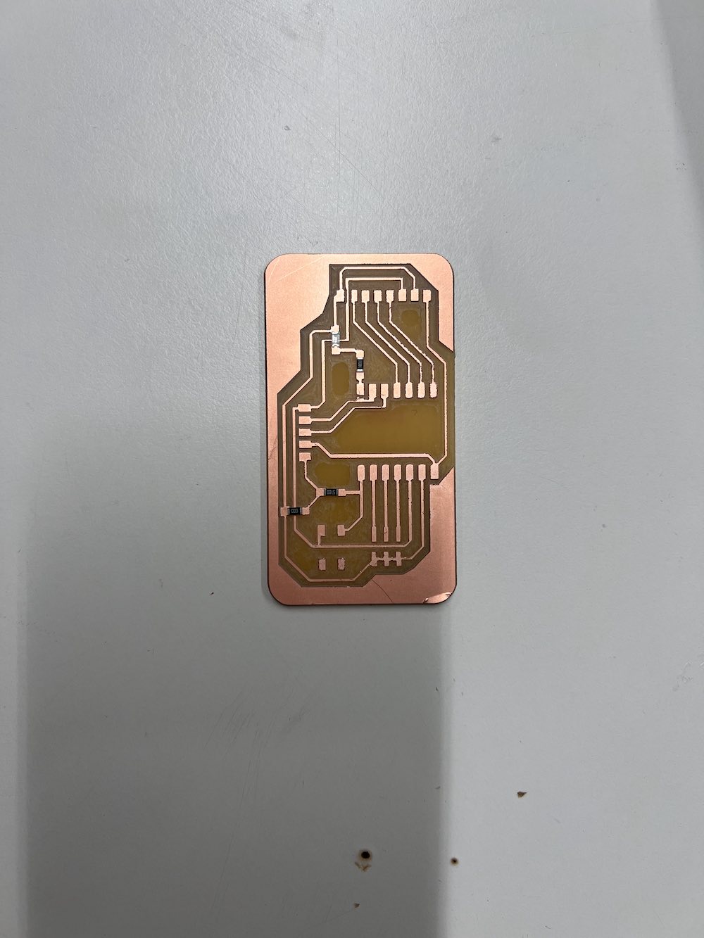
Once we had a successful mill of a PCB, we knew we could do it again. One of the main problems I faced was sizing and making sure there was copper remaining in my traces so power could still travel through the PCB. I went into more detail in my week 8 page.
Embedded Programming
In the embedded programming week, I was having trouble finding the proper Arduino IDE board for the microcontroller I am using, the Seeed Studio XIAO RP2040. Last week, I attempted to redo it. I was able to sucessfully find the board I needed through this website, How to Electronics. Once I got the correct board and port set up, I was able to successfully program my XIAO RP2040 to blink.
That page (week 4 assignment) can be found here.
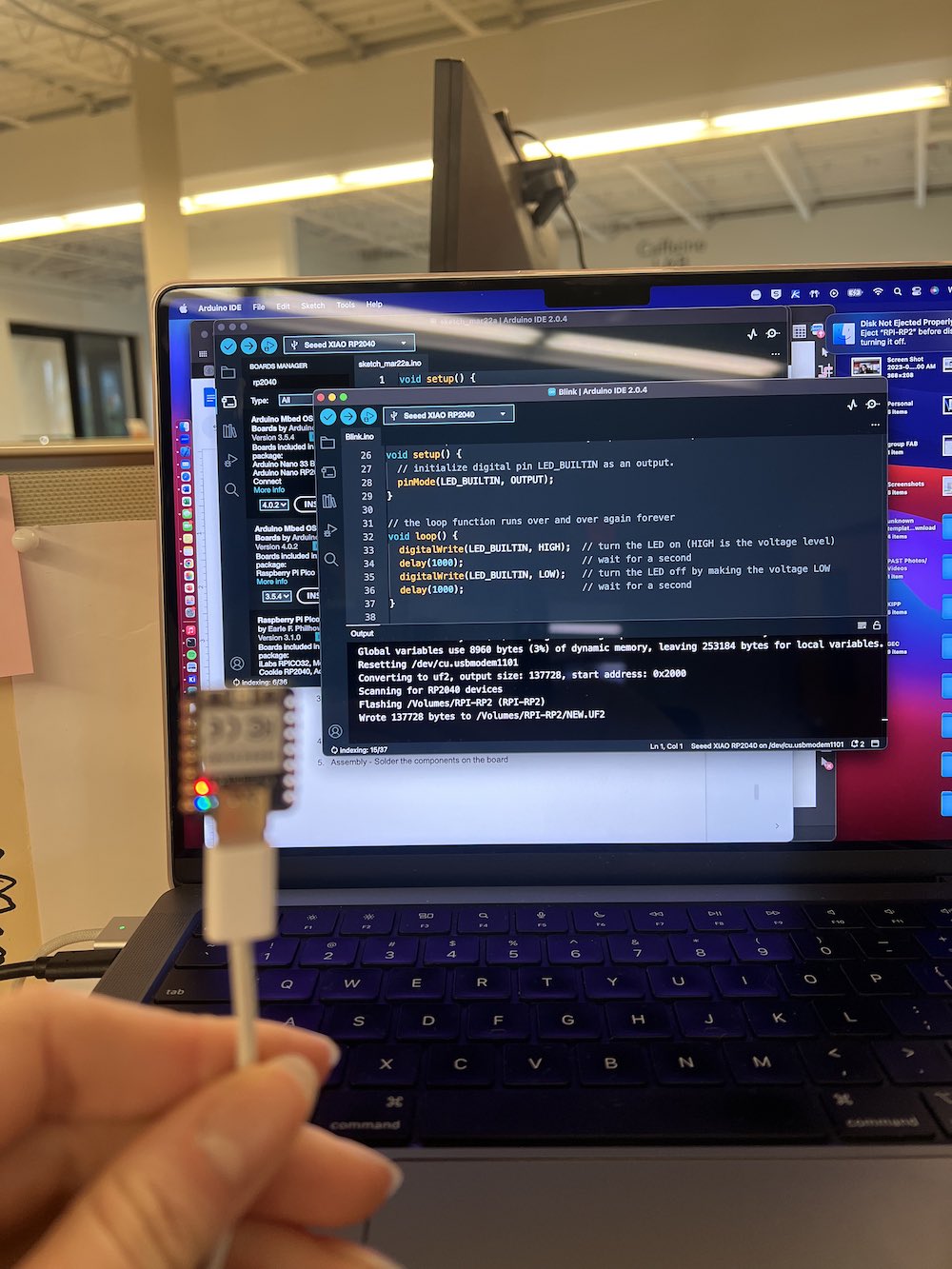
This is just an image of when I got the blink program to work. I have a video of another program I ran successfully where the LED flashes rainbow. I am working on compressing the file size before uploading it, to avoid having to reclone my repository to local.
Output Devices
With the knowledge I learned from the previous weeks of electronics (week 4, 6 and 8), I felt much more comfortable with the concepts that are required to do this weeks assignment. First, I started by selecting which output device I wanted to use. An output device is any hardware device used to send data from a computer to another device or use, according to techopedia.com.
I selected a Servo motor as my output device this week because my work has plenty on hand that we use for student programming, and it would be a good way to learn more about the details of the components that we use frequently at the PAST Foundation. A servo motor has many parts to its closed loop system; a control circuit, servo motor, shaft, potentiometer, drive gears, amplifier, and either an encoder or resolver. A servo motor can be AC or DC (current). I am going to be using a micro servo - the FS90R. This servo is continuous rotation, meaning it has a shaft that spins continuously, with a full rotational capacity of 360 degrees. The shaft has control over both speed and direction the servo rotates. From Pololu.com, I was able to find some details on the specifications of the motor. It can work with both 3.3 and 5 V signals. The maximum rotation speed is around 130 RPM (with no load). The FS90R can produce up to 21 oz./inch of torque.
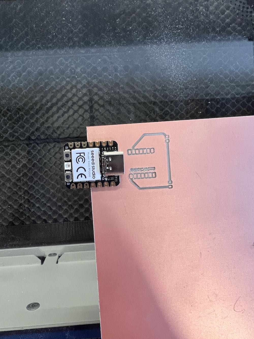
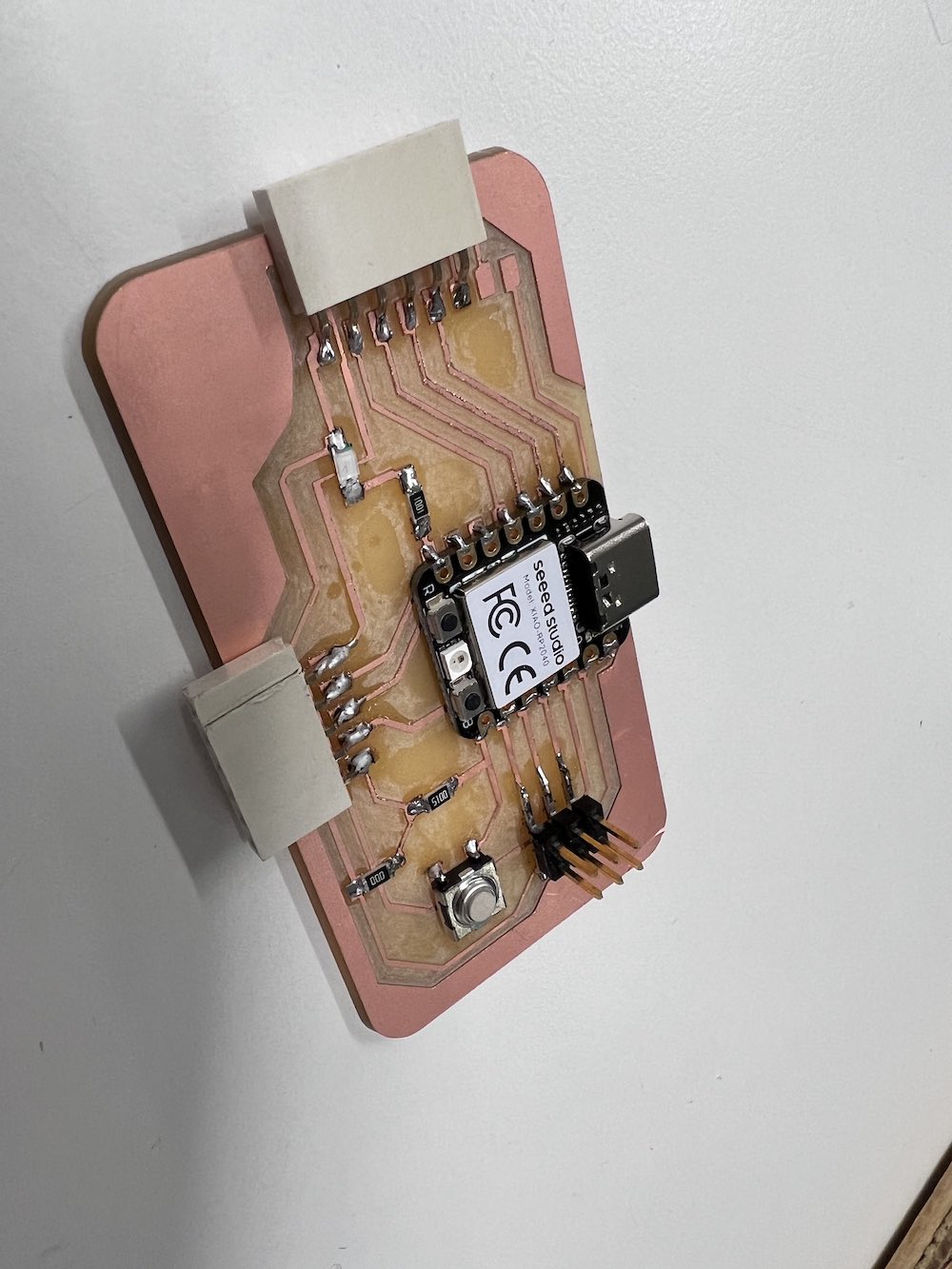
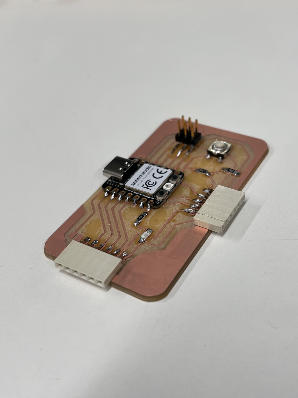
To get started, I needed to connect the board I made to the servo. Servo motors have 3 connection points; the brown wire is the ground pin, red wire is the power pin, and yellow is the signal connection. I used this information to connect my board.
Using male-male wires, I connected the servo's power to my 5V connector pin, the ground to my ground, and the signal pin to my pin D0. Once connected, I could input my code using Arduino IDE on my laptop.
Using code I found from Adafruit.com, and tweaking it slightly to match my pinout, I coded my servo to sweep. Below you will see my code I used.
Servo Example Code Sweep
/*
    Adafruit Arduino - Lesson 14. Sweep
    */

    #include

    int servoPin = D0;

    Servo servo;

    int angle = 0;   // servo position in degrees

    void setup()
    {
      servo.attach(servoPin);
    }


    void loop()
    {
      // scan from 0 to 180 degrees
      for(angle = 0; angle < 180; angle++)
      {
        servo.write(angle);
        delay(15);
      }
      // now scan back from 180 to 0 degrees
      for(angle = 180; angle > 0; angle--)
      {
        servo.write(angle);
        delay(15);
      }
    }
Before sending this code, I needed to make sure I had the proper library installed within Arduino IDE. Without the correct library, the servo may not work properly. I downloaded and installed "Servo" in the library manager within Arduino IDE. Then, made sure my board was connected to my computer and I had the correct board and port selected. Finally, I sent my code to my board and watched my servo move!