4. Embedded Programming
Our assignments this week are focused around embedded programming.
Group Assignment
The group assignment this week was the following:
You can find our group page here.
Comparing XIAO RP2040 and XIAO SAMD21
Unfortunately, at our lab right now, we have a very VERY limited selection of microcontrollers to explore and play around with. This SEVERELY limits my options for comparing the performance of various microcontrollers. The only two we have currently are the Seeed Studio XIAO RP2040 and the Seeed Studio XIAO SAMD21. They are almost exactly the same based on appearances, but have some key differences that you can see upcoming on this page. My individual assignment I used only the XIAO RP2040, but for the group assignment I read/skimmed the datasheets for both controllers, found out the specifications and features, and made a table to display some of the major similarities and differences.
I created this table with the anticipation that I would be comparing one more additional miccrocontroller, but unfortunately we do not have any in our facility currently. I am hoping that later on I can compare another architecture type that is different than the ARM.
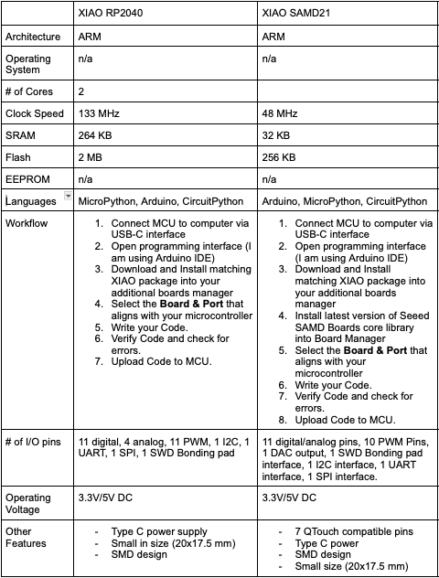
Note** the library download for the XIAO package is the same for both of these boards (in Arduino IDE --> additional boards manager --> URL input). More information is available below for programming the rp2040. The next step after, is searching for either the XIAO rp2040 library or the SAMD21. Depends on which you are using.**
The RP2040 and the SAMD21 are very similar in a lot of ways. Some key differences I noticed are the clock speeds (rp2040 much faster than samd21), memory capacities for Flash and SRAM, and the pins themselves. The SAMD21 supports QTouch, which offers built-in hardware for touch measurements for sensors, buttons, sliders, etc. This can add a different component to a project that may elevate your design compared to using an rp2040.
Both microcontrollers have UART, SPI, and I2C capabilities. Overall, the two boards, given they share the same architecture, overlap a lot in their features and functions.
Research
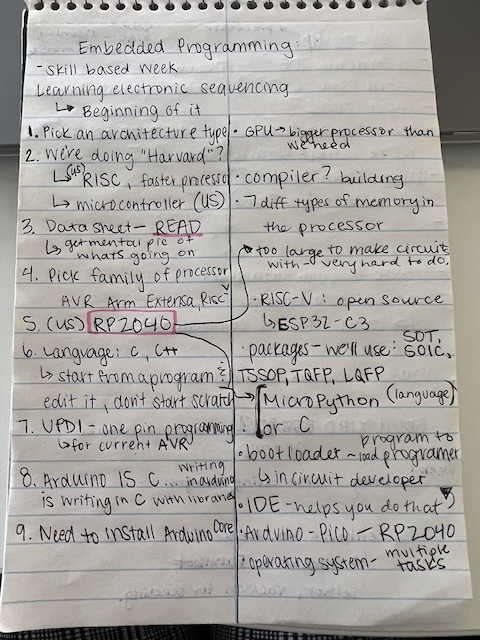
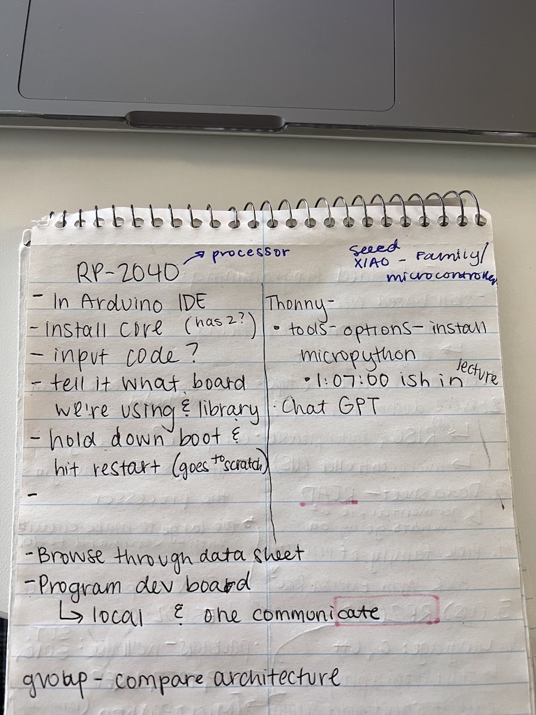
This week's lecture content was extra confusing for me because I have no prior experience or knowledge on programming, microcontrollers, developent boards, etc. I began by rewatching the lecture video to try to gain clarification and took notes on the steps Neil Gershenfeld (our instructor) did. This allowed me to block out any information that was not relevant to the architecture I would be using and save it for later. I will attach an image of my notes I took below.
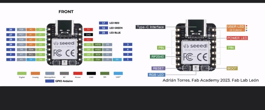
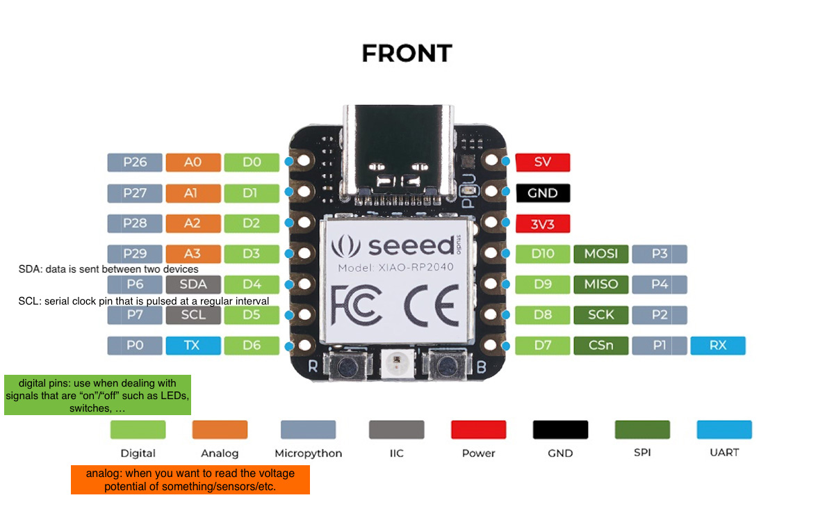
From the data sheet, I was able to see the power available to use with the Seeed Studio XIAO RP2040, which is 3.3V/5V of working voltage. I was also able to see the correct pinouts, what each can be used for, and more from reading through the datasheet. It is massive (a whopping 600 pages) but skimming over it was very useful in understanding more about the RP2040.
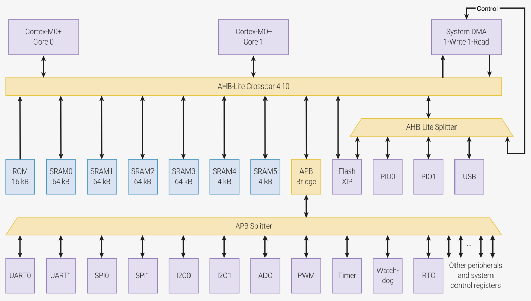
The bus fabric routes addresses and data across the chip. These paths are all 32 bits wide. It says in the datasheet that there are 4 "masters" (devices which generate addresses) which are routed to 10 downstream ports. The "masters" can access any 4 different crossbar ports simultaneously. At a clock of 125 MHz, the maximum bandwidth for the bus is 2.0 GB/s. This is the maximum number of bits per second that can traverse this bus.
Much more information can be found through this link to the XIAO RP2040 datasheet.
XIAO RP2040
Programming the Seeed XIAO RP2040 processor
Necessary Downloads
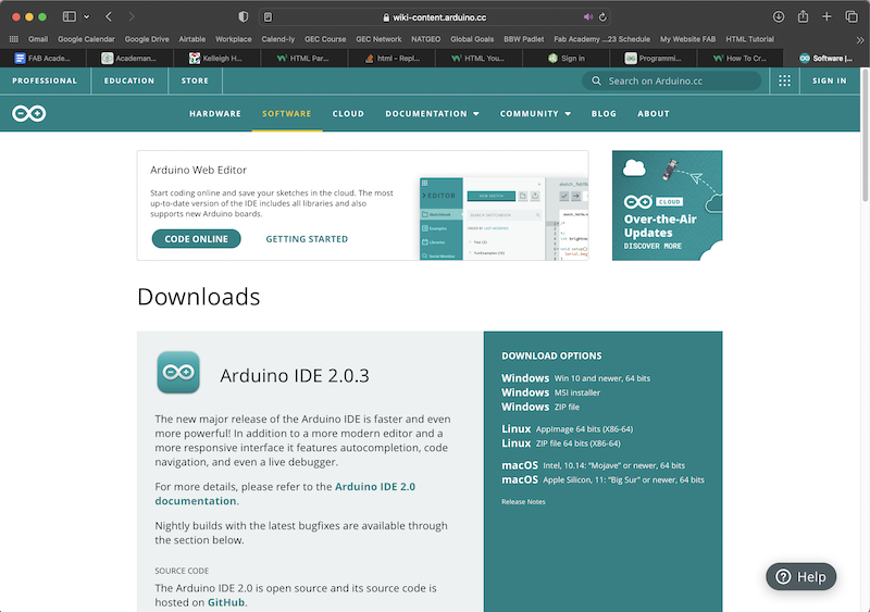
The first thing I needed to download was the Arduino IDE. I did this through the Arduino website.
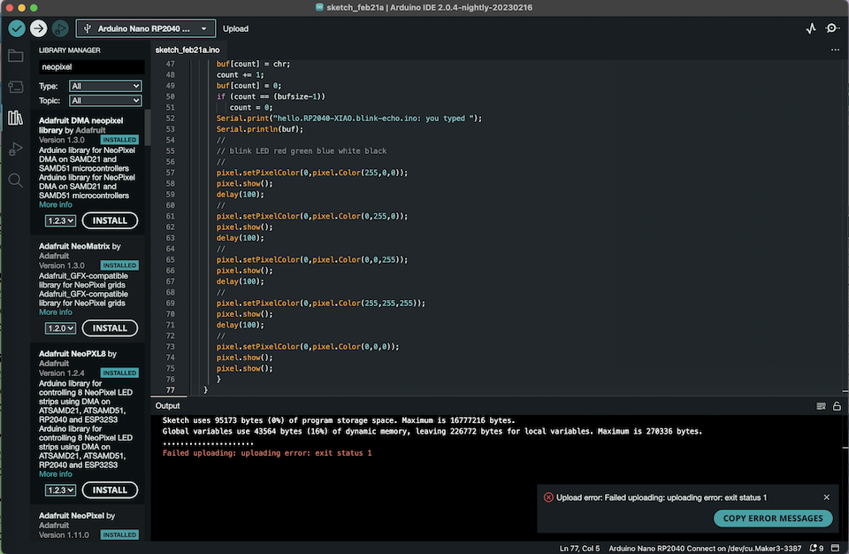
Once I had Arduno IDE, I needed to install the Adafruit NeoPixel library within the application. This will allow our code to upload properly and to help us get our LED light to blink. I also needed to select the correct board and port.
Trial 1 - Blink
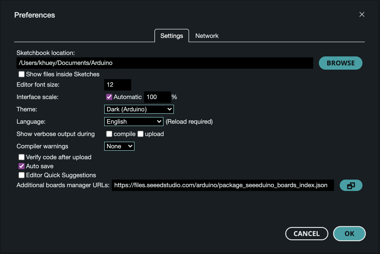
I first needed to choose the correct board. I am using the Seeed XIAO RP2040 microcrontroller and processor, which does not shpw up in the Arduino IDE. I had to navigate to the preferences through file, then in the "Additional Boards Manager URLs" I input a link
https://chat.academany.org/fabacademy-2023/messages/7d39d07027ce0c9ceee66807754b8514366a6250#. For reasons unknown, the Seeed XIAO RP2040 would not show up in the board list, or when I search it, even after I imported the URL through the additional boards manager.
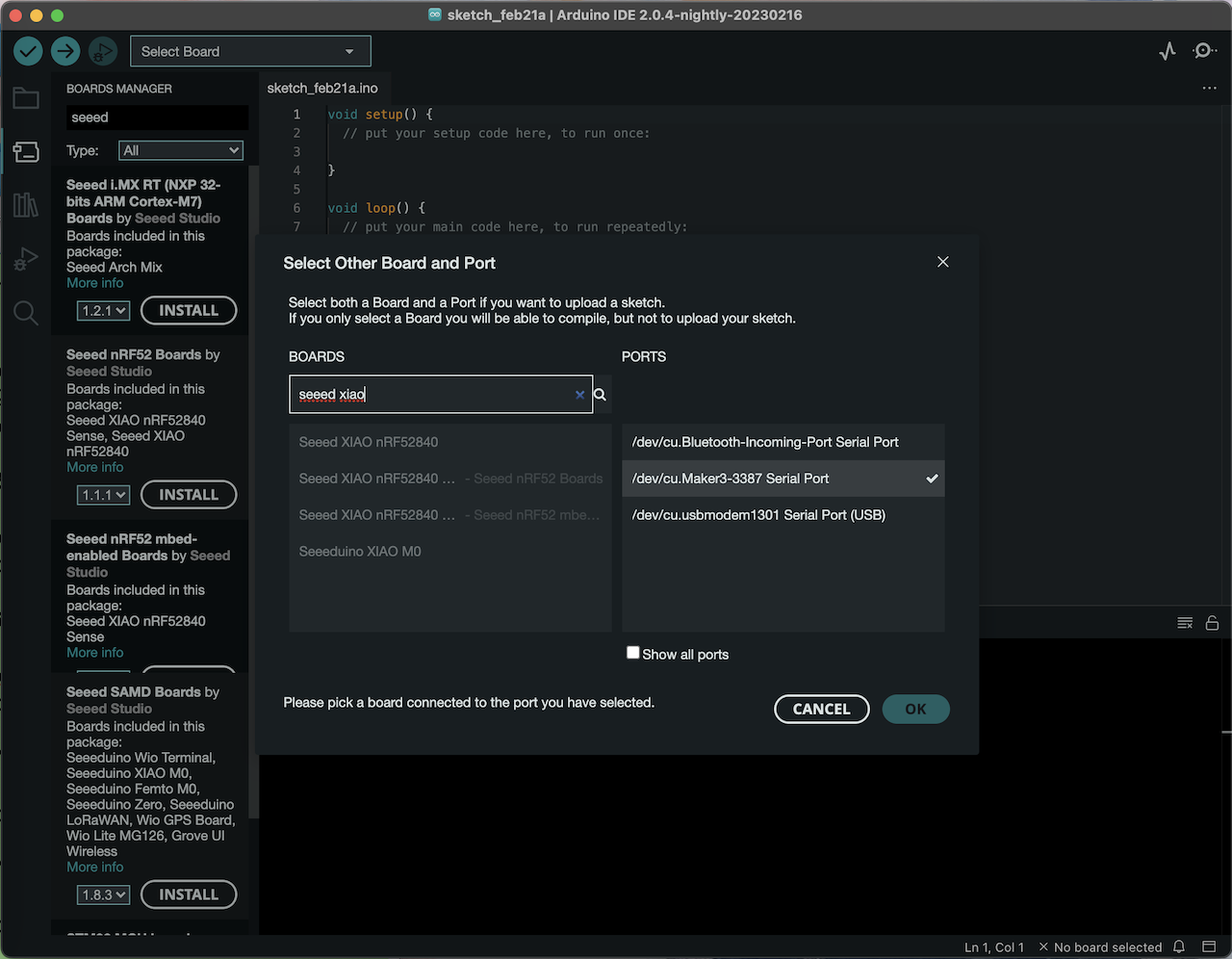
I also needed to find the correct port and set that up. The port I needed was the serial port through my usb, that is where I have my connection to the microcontroller.
Trial 2 - Blink
After some digging and research, I was able to find a different link with the proper board for the XIAO RP2040. I found the Seeed Studio website and was able to follow these steps to getting started with the XIAO through Arduino IDE.
A list of my steps can be found below. The first steps through the successful blink was done with help from the Wiki Seeed Studio Page.
- Plugged in microcontroller - I used my USB-C connector and cord to connect my XIAO to my computer. I then pushed and held the Boot button on the microcontroller. A disk called "RPI-RP2" showed up on my computer, so I knew the connection was made.
- Downloaded Arduino IDE - Using the link above in downloads, I downloaded the program to my computer. I previously uninstalled it after my first set of trials to see if it would maybe fix a bug.. I'm not sure. But I redownloaded it anyways and opened the application.
- Adding XIAO Board - Through file, then preferences, I clicked on Additional Boards Manager URLs and pasted this
https://github.com/earlephilhower/arduino-pico/releases/download/global/package_rp2040_index.json
into it. - RP2040 Board Package - Navigate to Tools in the top toolbar, then click Board --> Board Manager. In the search, type "RP2040" and install the latest version of the Raspberry Pi Pico package.
- Select Board & Port - I selected my Seeed XIAO RP2040 board and selected the USB connection as my port.
- Run an Example Code - Through file --> Examples, I selected the 01.Basics and then chose the Blink example to run. Once I clicked this, it autopopulated the code into the working space and I could then click upload. This caused the LED on my microcontroller to blink! Successful connection!!
Once I knew I had the proper connection and was capable of uploading and running code through my microcontroller, I tried another code to get the LED to blink. This was done with the help of the How2Electronics page .
LED Blink Code - 1 Second Interval
The code I used is below:
 // the setup function runs once when you press reset or power the board
        void setup()
        {
          // initialize digital pin LED_BUILTIN as an output.
          pinMode(LED_BUILTIN, OUTPUT);
        }

        // the loop function runs over and over again forever
        void loop()
        {
          digitalWrite(LED_BUILTIN, HIGH);   // turn the LED on (HIGH is the voltage level)
          delay(5000);                       // wait for a second
          digitalWrite(LED_BUILTIN, LOW);    // turn the LED off by making the voltage LOW
          delay(2000);                       // wait for a second
        }
Once I was able to paste this code into Arduino IDE, I hit upload.
Blink Success
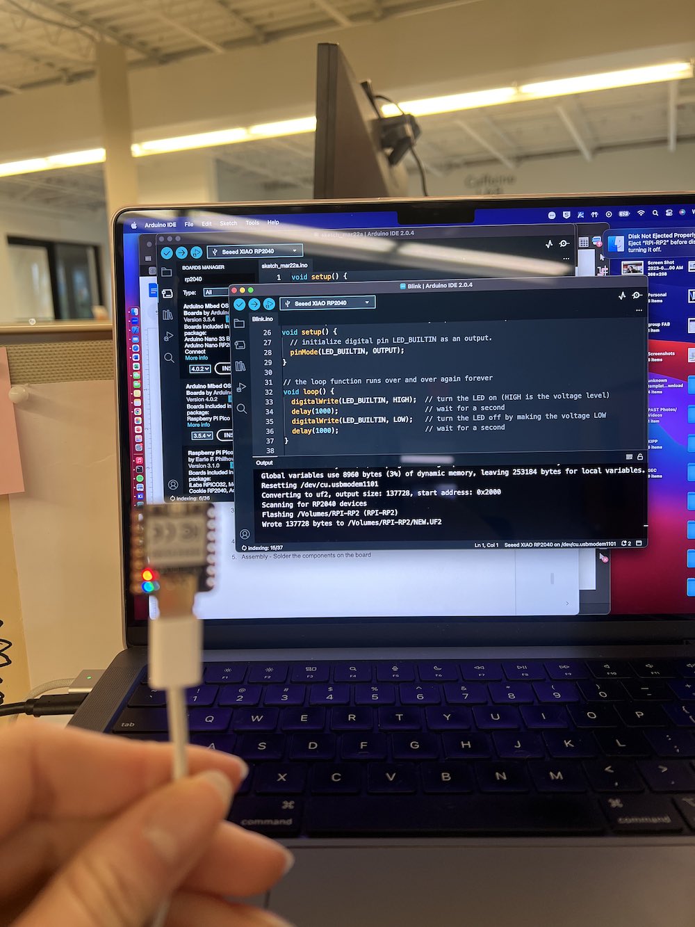
Above is a still-shot of my microcontroller running the blink program with its LEDs.
Now that I had gotten this done correctly and know more about what I am doing, I wanted to try to interact with the neopixel RGB LED. To do this, I did the following (found from How2Electronics):
- Adding a 3rd Party Library - Through Arduino IDE, click sketch > Include Library > Manage Libraries. Then, type "Adafruit Neopixel". This should bring up the library you need for interacting with pin 11 and the RBG LED. Install the latest version of it.
- Source Code - The code I used to flash the RBG LED was
 #include

        int Power = 11;
        int PIN  = 12;
        #define NUMPIXELS 1

        Adafruit_NeoPixel pixels(NUMPIXELS, PIN, NEO_GRB + NEO_KHZ800);

        void setup()
        {
        pixels.begin();
        pinMode(Power,OUTPUT);
        digitalWrite(Power, HIGH);

        }

        void loop() {
        pixels.clear();
        pixels.setPixelColor(0, pixels.Color(15, 25, 205));
        delay(400);
        pixels.show();
        pixels.clear();
        pixels.setPixelColor(0, pixels.Color(103, 25, 205));
        delay(400);
        pixels.show();
        pixels.clear();
        pixels.setPixelColor(0, pixels.Color(233, 242, 205));
        delay(400);
        pixels.show();
        pixels.clear();
        pixels.setPixelColor(0, pixels.Color(233, 23, 23));
        delay(400);
        pixels.show();
        pixels.clear();
        pixels.setPixelColor(0, pixels.Color(12, 66, 101));
        delay(400);
        pixels.show();
        delay(500);
        }
- Upload Code - Now that I have my code in, I am able to push the upload button and the programming should start.
This is a video of the blink on the RBG LED successfully running.