Week 9. Output Devices
Group Assignment
This week, we discussed output devices. An output device is any component which converts information from the microcontroller to a perceivable form by humans.
The group assignment is to: "measure the power consumption of an output device."
Power
First, what is Power?
The power in an electrical circuit is a measure of how much work can be done in a certain amount of time. This can be measured with a multimeter. The formula for power is P=I*V . Power (P) is measured in watts, voltage (V) is measured in volts, and current (I) is measured in amps.
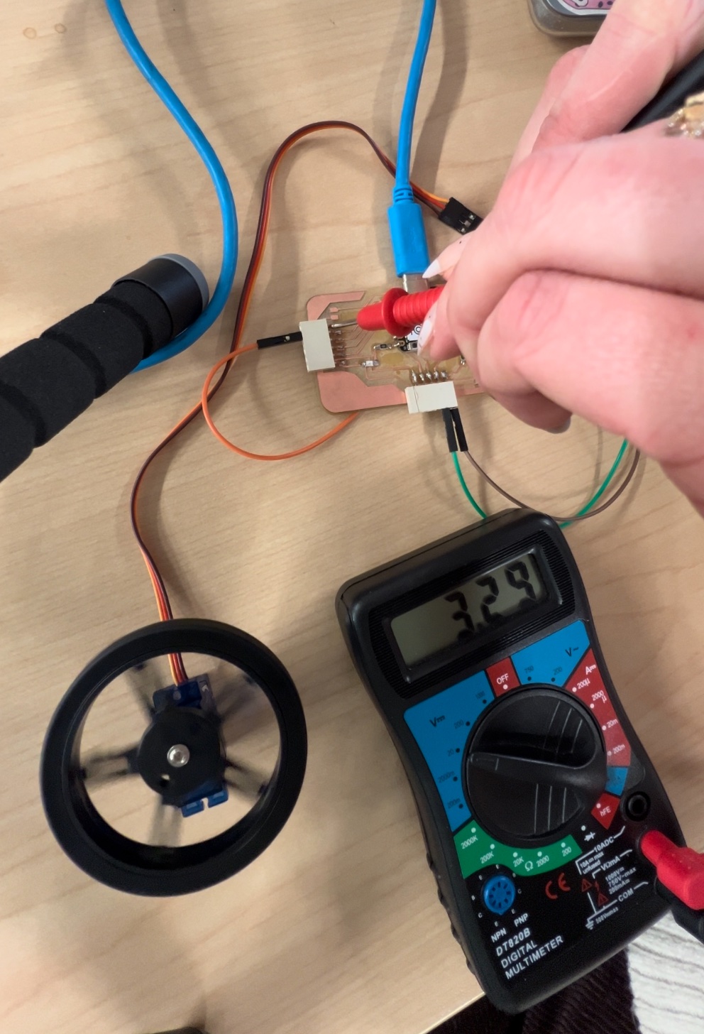
We used a multimeter to test the power consumption of our output device, the servo motor. To do this, we touched the black wire of the multimeter (ground) to the ground pin of the board, and touched the red wire probe to the pin with the servo attached. Our reading was pretty consistent around 3.29 V.
After measuring voltage, we realized that for this assignment, we needed to measure current (amps).
Voltage vs Current
Current and voltage are not the same. Voltage is the potential, current is the actual flow, so to measure current, you essentially have to break the circuit.
Voltage
- Voltage: Voltage is the measure of electric potential energy per unit charge. It is the electrical force that drives electric current between two points.
- Unit: Voltage is measured in volts (V).
- Symbol: It is represented by the symbol "V".
- Effect on the Circuit: Voltage is the force that drives current through a circuit. It is the cause, and it can exist without current.
- Measuring Instrument: Voltage is measured using a voltmeter, which is connected in parallel to the component where the voltage drop is to be measured.
Current
- Current: Current is the rate at which electric charge flows through a circuit. It is the actual flow of electrons.
- Unit: Current is measured in amperes (A).
- Symbol: It is represented by the symbol "I".
- Effect on the Circuit: Current is the flow of electric charge, and it is dependent on the circuit's resistance. It is the effect, and it cannot flow without voltage.
- Measuring Instrument: Current is measured using an ammeter, which is connected in series with the component being measured.
In summary, current is the flow of electric charge, measured in amperes using an ammeter, and it is the effect that cannot flow without voltage. Voltage is the electrical force driving the current, measured in volts using a voltmeter, and it is the cause that can exist without current.
Helpful Sites
Video: How to measure current of servo Multimeter BasicsStep 1: Reconfigure multimeter
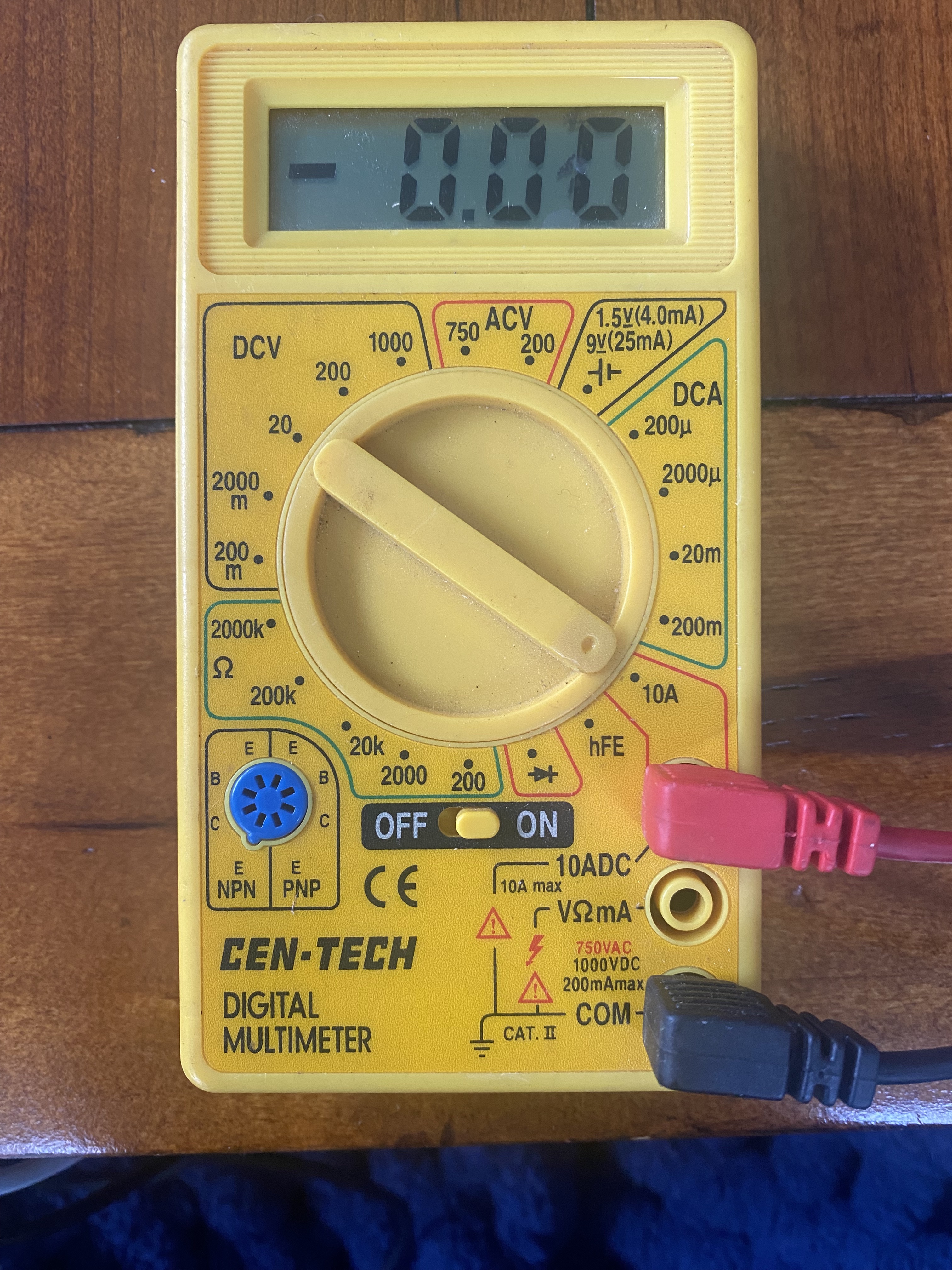
First, you need to configure the multimeter to read current. Measuring current with a multimeter is a bit trickier than measuring voltage or resistance. First, you need to set the multimeter to the current function and choose AC or DC. Then, put the red probe in the 'A' jack and the black probe in the 'COM' jack. Finally, place the probes in the circuit where you want to measure the current. This will help you find out how much current is flowing through the circuit. You can also watch this video for a visual guide: How to Measure Current with a Multimeter
Here is an image that shows how the multimeter should be set up to read current:
Step 2: Reading the current:
To measure the current in a servo motor, you would typically need to use a current sensor or a multimeter. The specific placement of the probes or sensor can depend on the setup of the servo motor and the availability of access points for measurement. However, in general, the most common way to measure the current in a circuit is by placing the current sensor or the multimeter in series with the load (in this case, the servo motor). This means interrupting the flow of current from the positive terminal of the power supply to the positive connection of the load, and then from the negative connection of the load to the negative terminal of the power supply. The current sensor or the multimeter is then placed in this interruption to measure the current flowing through the circuit. It's important to ensure that the current sensor or multimeter is set to an appropriate range for the expected current draw of the servo motor.
In summary, to measure the current in a circuit, you should place the red probe of the multimeter on the positive side of the circuit and the black probe on the negative side. When measuring the current in a servo motor, you would place the probes in series with the circuit, ensuring that the current flows through the multimeter.
Ran into trouble...
Servo motor stopped working or “pulses” rather than running consistently. See video:
According to reserach... the reason for this may be...
...The servo motor may stop when measuring the current due to the multimeter's internal resistance affecting the circuit. The lower current-measuring range of the multimeter can introduce too much series resistance, causing the servo to drop the supply voltage when it tries to draw current. This can lead to unexpected behavior, including the servo stopping. Additionally, the fast spikes in current draw by the servo motor may not be accurately captured by the multimeter. It's important to use the appropriate current-measuring range and consider the impact of the multimeter's resistance on the circuit when measuring the current drawn by the servo motor
...Measuring the current in a servo motor can impact its performance due to the dynamic nature of the current draw. When a servo motor is in operation, the current it draws can vary based on factors such as the load and its movement. The current may have a pulse waveform, with the duration of the pulse changing based on the motor's activity. Additionally, the current draw may not be constant, as it can drop to almost zero when the servo reaches its desired position and then increase when it is pushed out of position. Therefore, when measuring the current draw of a servo motor, it's important to consider the dynamic nature of the current and its impact on the motor's overall performance
After revisiting the project and trying it all again we were able to power the servo with a 9V battery and successfully measure current as seen in the video below.
We got a reading of about 2.7 mA when measuring current through the servo motor.
Individual Assignment
I decided to experiment with a servo motor for this assignment. We use servo motors for a variety of projects at the PAST foundation with students and it's a versatile and user friendly output device that can be applied to many projects.
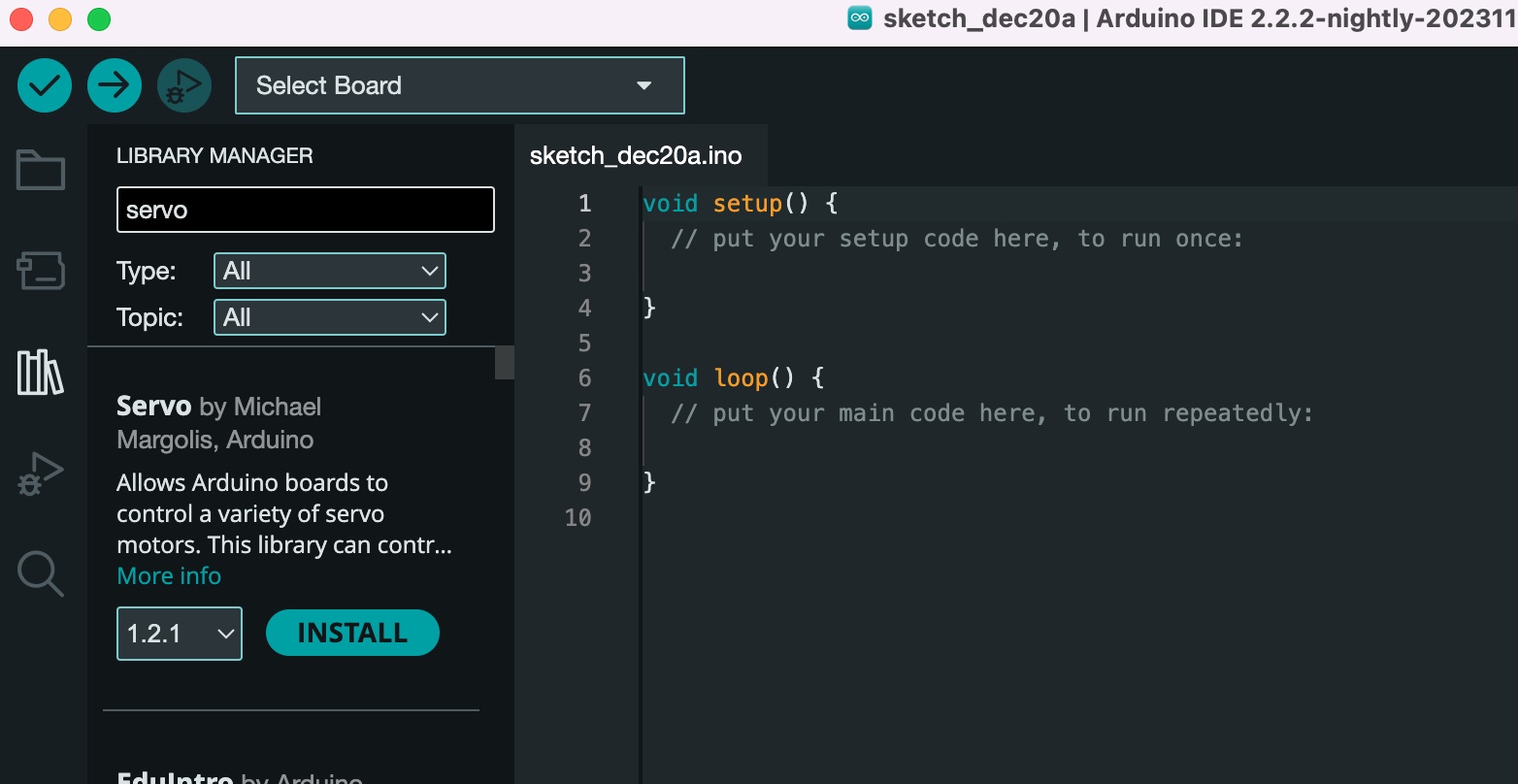
To start, I first installed “Servo” from Arduino IDE library, pictured below.
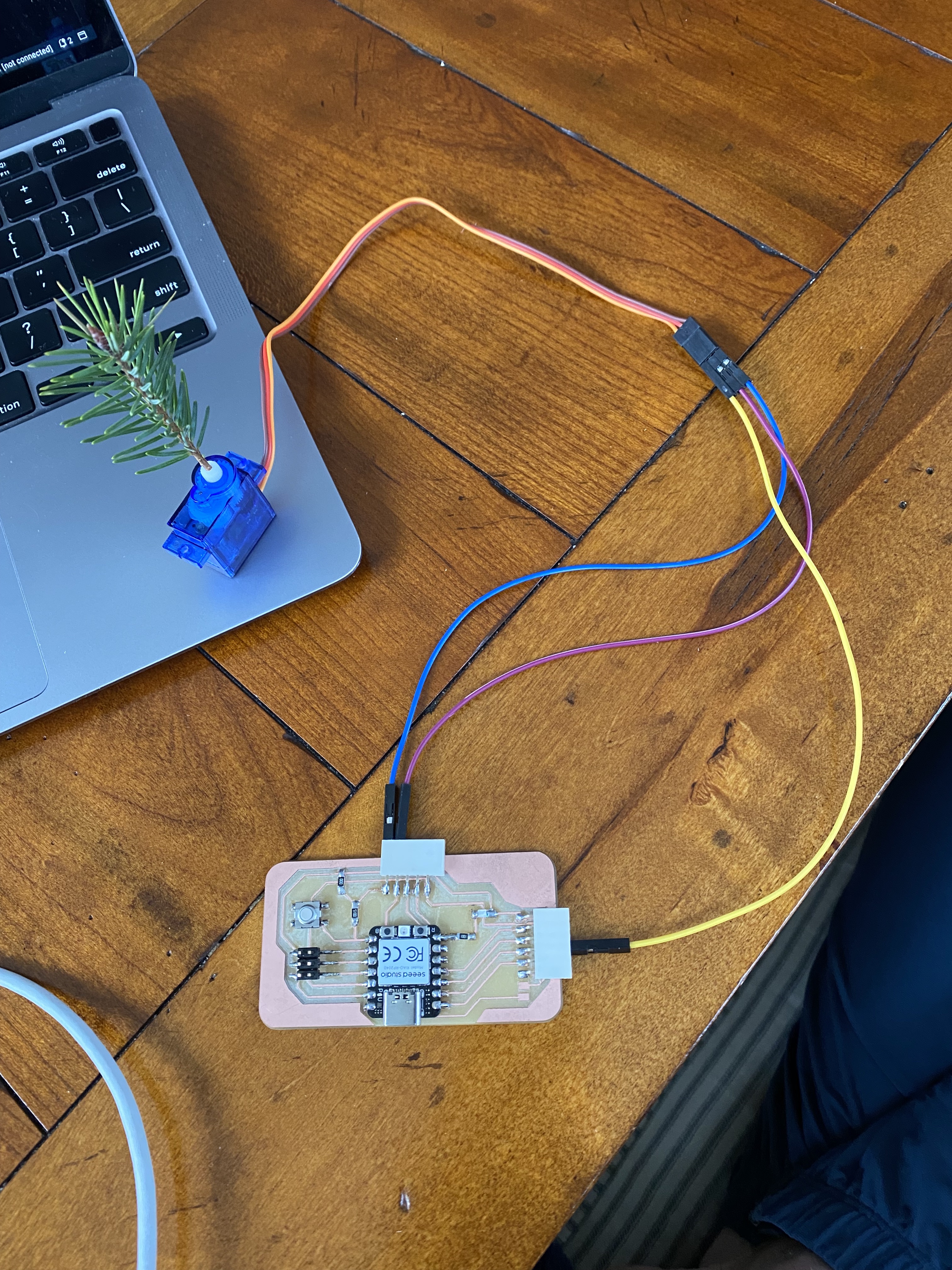
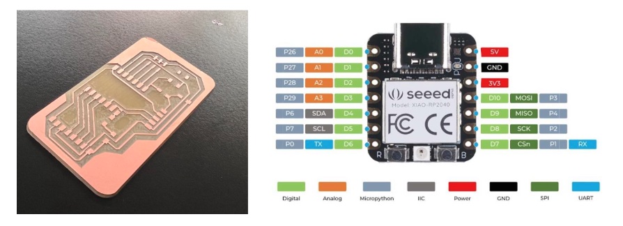
Using the servo motor, I used male to male wires to connect the signal pin (orange wire) to P27, the power (red wire) to my 5V, and the ground (yellow wire) to my ground. I had to refer to my PCB layout and the pico reference board below frequently to ensure I had the wires in the correct places.
I tried several variations of code and everytime I ran it the servo would not move. There was only slight movement when I first plugged in the 5V wire, and then it would stop. You can see the issue I was experiencing below:
After a lot of trial and error and research, it seemed as though the speed setting for my servo may have been too high. I used the tips from this video and rewrote my code to adjust the speed settings, and it finally worked. Here is the working code:
          #include


          Servo myservo;  // create servo object to control a servo
          // twelve servo objects can be created on most boards


          int pos = 0;    // variable to store the servo position


          void setup() {
           myservo.attach(27);  // attaches the servo on pin 27 to the servo object
          }


          void loop() {
           for (pos = 0; pos <= 180; pos += 1) { // goes from 0 degrees to 180 degrees
             // in steps of 1 degree
             myservo.write(pos);              // tell servo to go to position in variable 'pos'
             delay(15);                       // waits 15 ms for the servo to reach the position
           }
           for (pos = 180; pos >= 0; pos -= 1) { // goes from 180 degrees to 0 degrees
             myservo.write(pos);              // tell servo to go to position in variable 'pos'
             delay(15);                       // waits 15 ms for the servo to reach the position
           }
          }
And here is a video showing the servo motor finally working (with a miniature christmas tree in light of the holiday season!)
Here is a photo to show how the servo motor is wired: