Assignment
Individual Assignment:
- Make (design+mill+assemble) something big (~meter-scale)
- Extra credit: Don't use fasteners or glue
- Extra credit: Include curved surfaces
Group Assignment:
- Do your lab's safety training.
- Test runout, alignment, fixturing, speeds, feeds, materials and toolpaths for your machine
- CNC: Computer Numerical Control
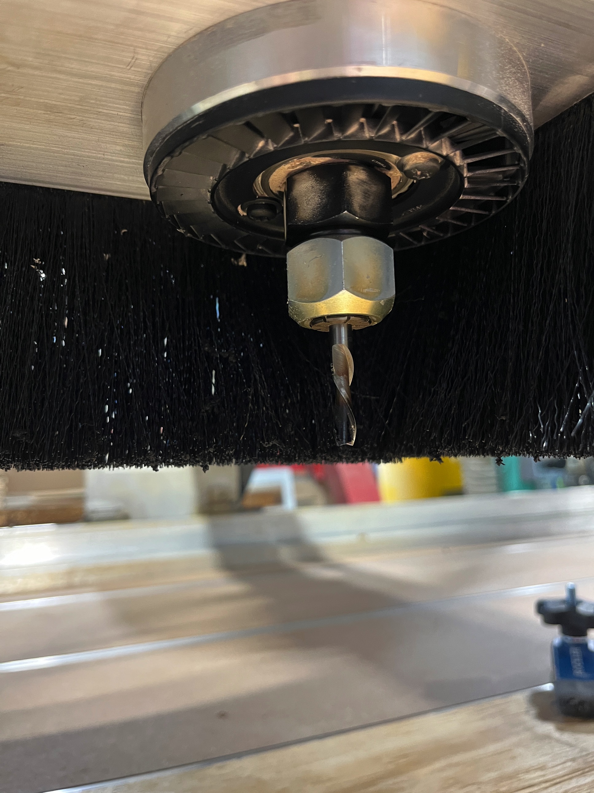
- End Mill: A cutting bit used for milling
- Spoil Board: A sacrificial surface from which to hold objects down on and not be overly concerned when an endmill goes too deep and cuts into it.
- Alignment: Levelness and straightness of the spoil board
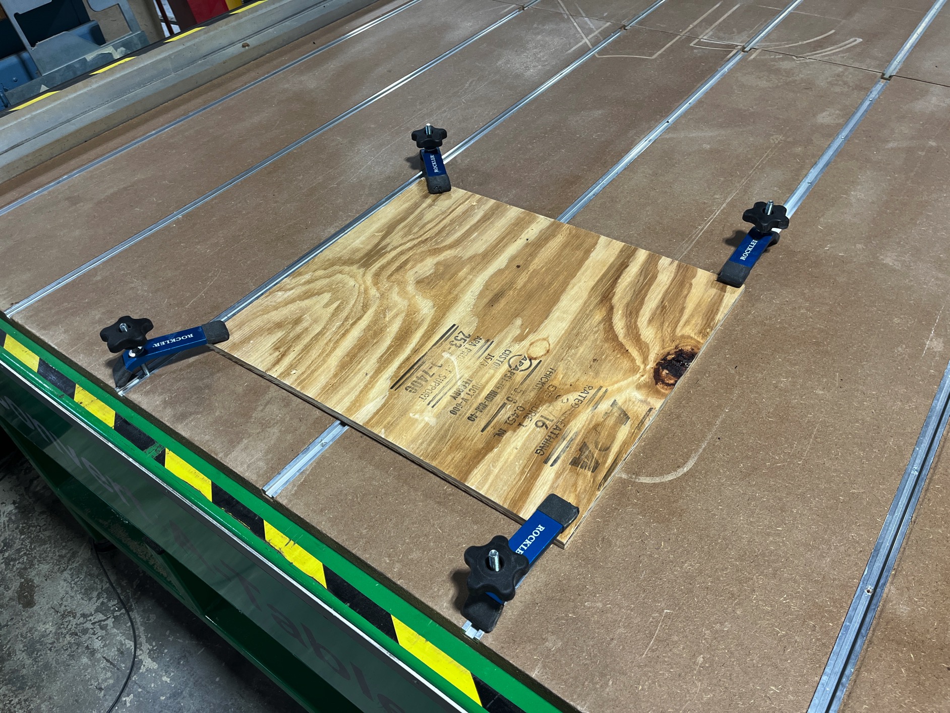
- Fixturing: How material is held to the spoil board in order to be cut on the bed
- Flute: A channel on an end mill to direct the cutting debris
- Runout: Runout refers to inaccuracies in a tool or piece of equipment that cause it to spin off its ideal axis. Spindle runout occurs when a spindle no longer rotates on its intended axis, which can result in: Issues with tolerance control. Inaccurate machine registration. Excessive chip load.
- Toolpath: The path that the endmill follows to cut the material
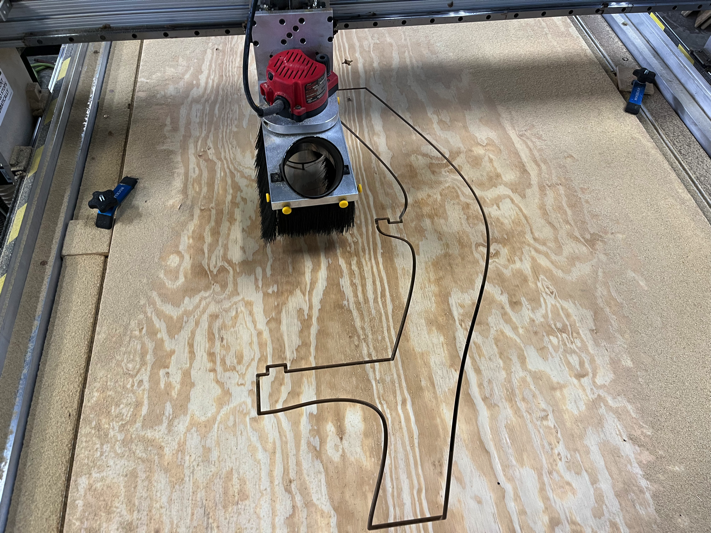
- Tabs: Small sections of material that the machine does not cut to hold material in place when cutting through the entire thickness of material
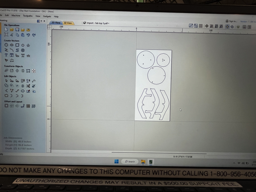
- Import files into Cut 2D Pro (.dxf files are preferred).
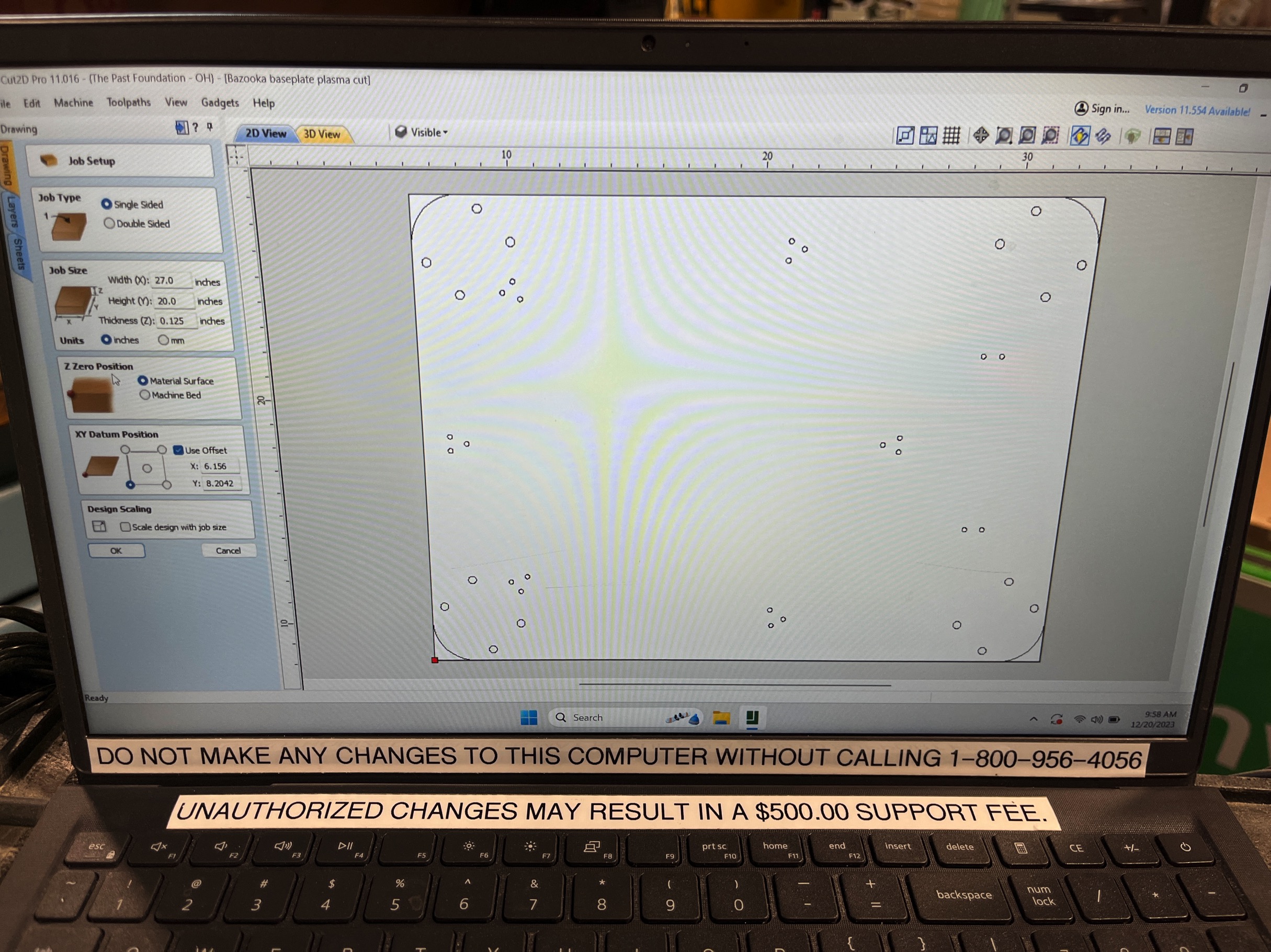
- Set Material Size: Ensure that the overall material size matches or exceeds the size of the finished product. You can do this in the Job Setup section.
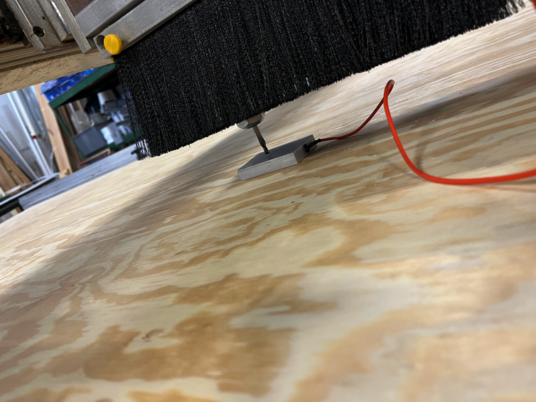
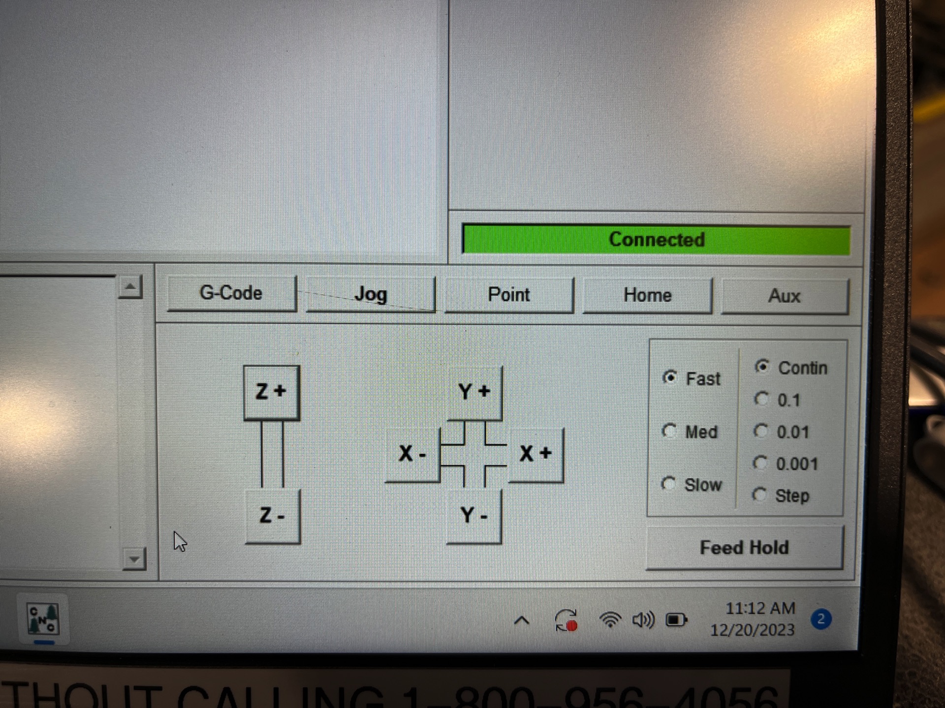
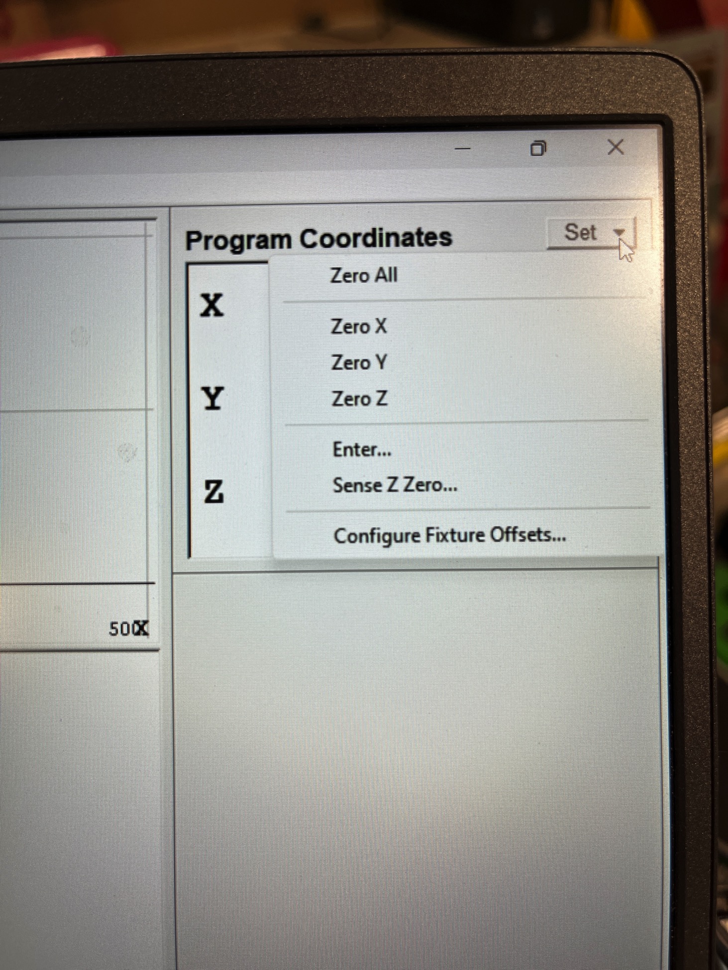
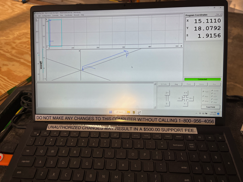
- Set X, Y and Z zero for material: Manually move the router head to the X and Y the respective edges of your material alining with the tip of the bit. To set Z zero manually move the router head to the middle of your material and use the Z-zero touch pad.
- Select Vectors: Start by selecting the vectors you'll be using for machining onto appropriate layers (if applicable).
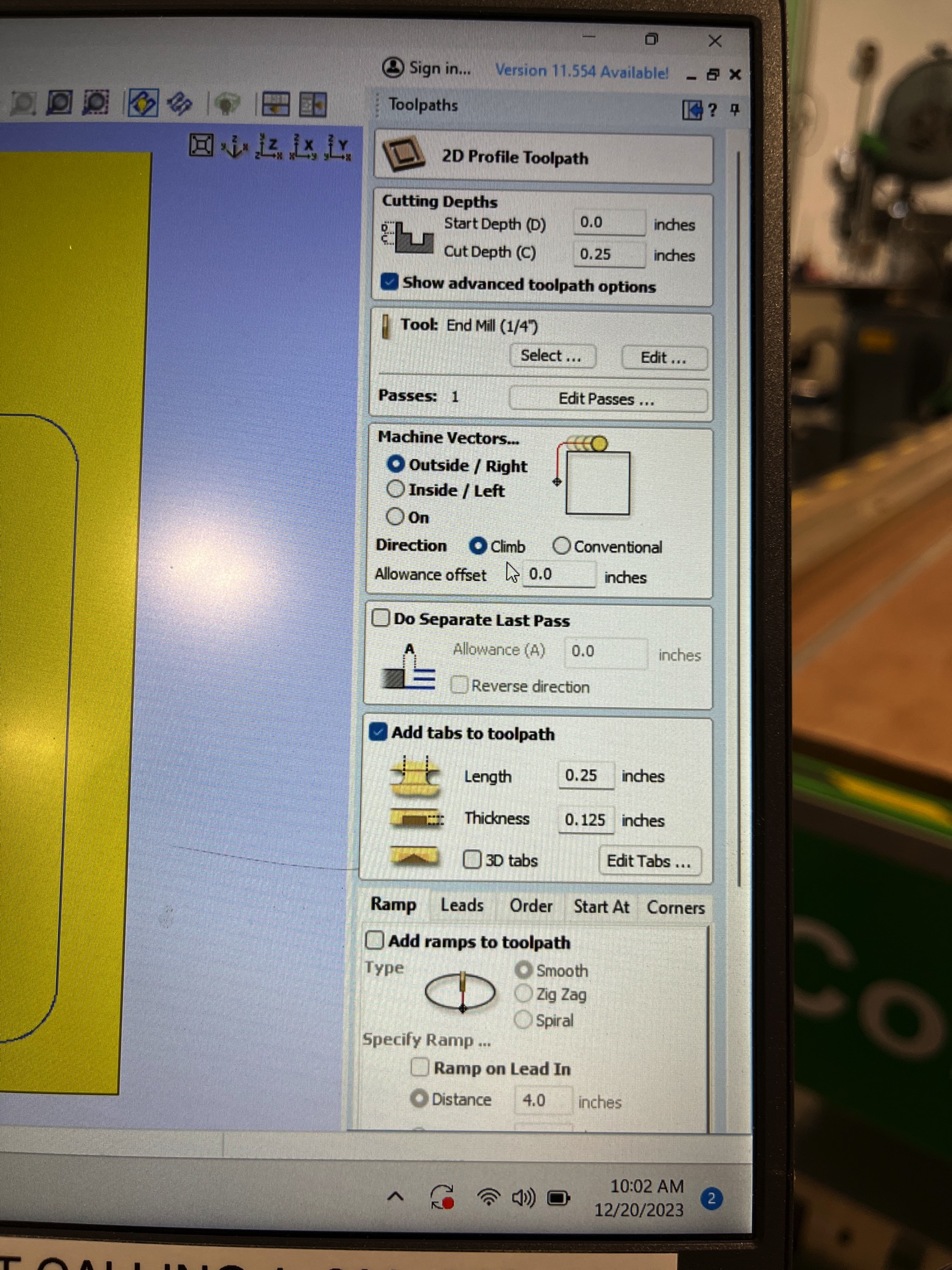
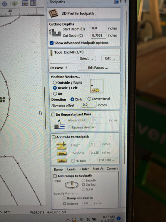
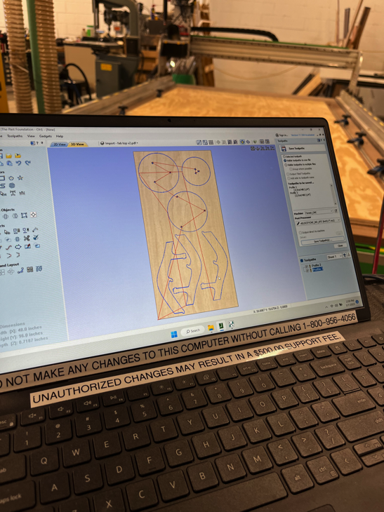
- Choose Tool path Strategy: Work through the tool path strategy icons (pocket cut, profile cut, engrave or drill) you wish to use to machine the job. This will calculate all the required tool paths.
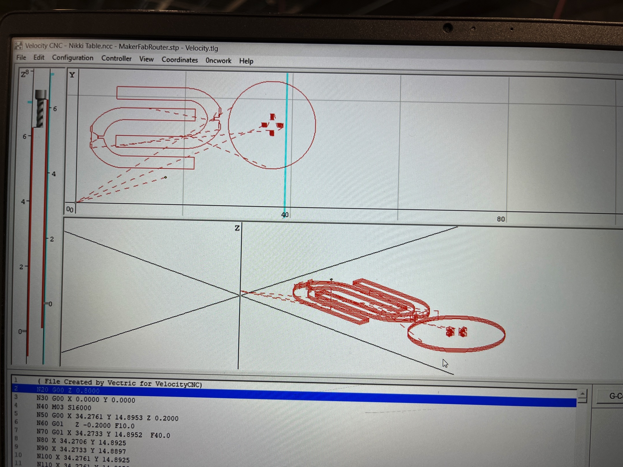
- Preview Tool paths: After creating each tool path or at the end of calculating them all, preview the tool paths in the 3D view. This step is important to verify the position, detail, and look of the overall finished part.
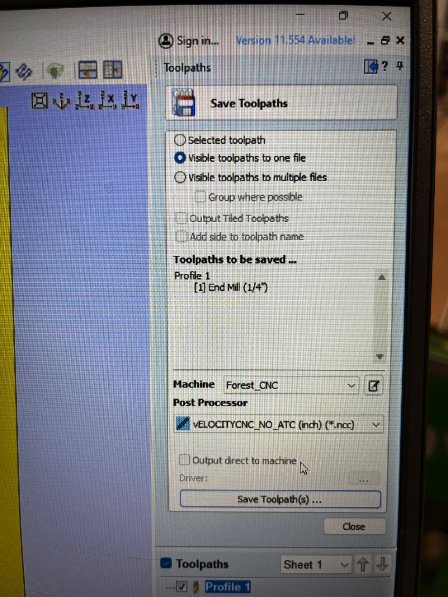
- Save Tool paths: Choose the appropriate Post-processor. In our case we are using the ForestCNC router.
- Spiral development saves a lot of time, headaches and material.
- Be sure to use good CAD practices! It will pay off when it comes time to making changes….USE parametric dimensioning.
- Always uncheck offset when setting up .dxf in Cut2D Pro. If you forget your part may be "outside" cutting area
- Dogbone feature works well for inside cuts.
- DXF did much better than SVG
- Grouping is for moving elements together, joining is for turning them into one vector.
- Adding tabs to tool path is very helpful with the type of fixturing we have. We can not cut into the spoil board so Tapered 0.25” tabs are preferable to 0.125”
- For safety add fixturing elements to Cut2D Pro work area to be sure you do not cut into the fixturing tool.
- Also it is important to send the router head to "HOME" after job is done and before turning everything off. This makes it easier for starting the next job since the router is already HOME.
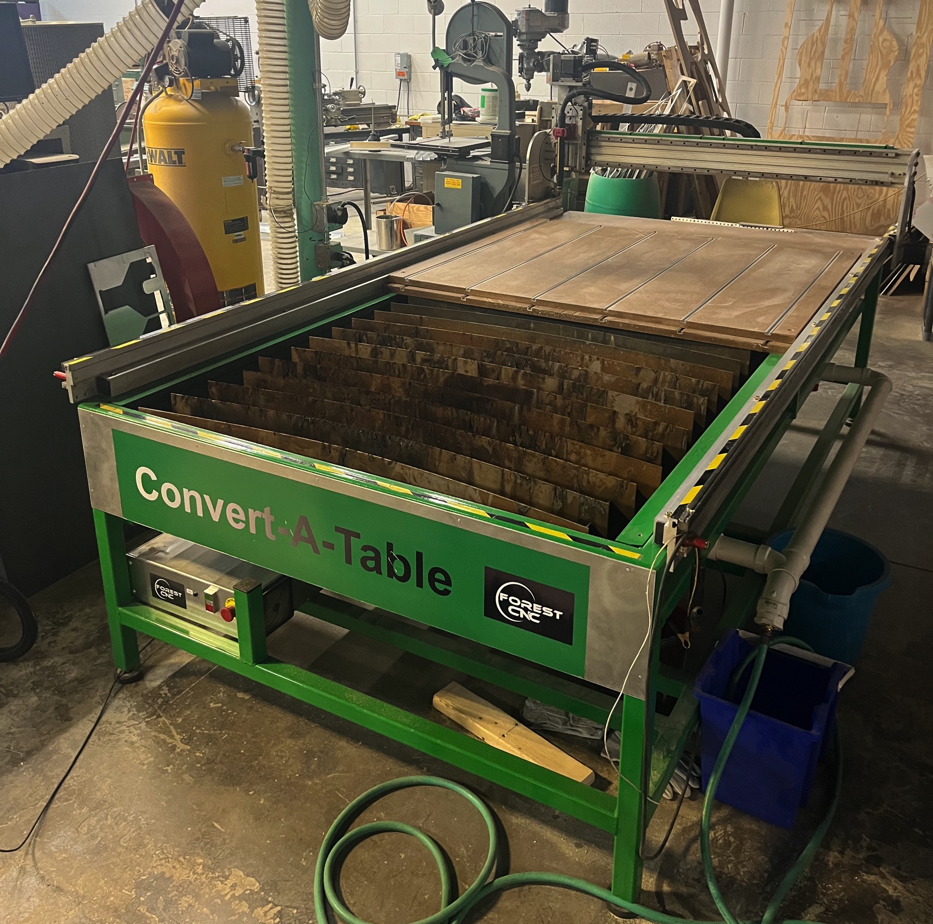
Computer Controlled Machining Group Assignment
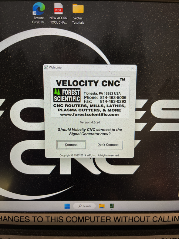
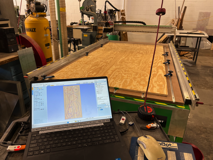
Our CNC Machine is a 96x48 Forest CNC Convert-A-Table. This means that it is a CNC plasma table AND and a CNC router. It can plasma cut metals when the spoil board is removed and the bed is filled with water. After draining the water table the spoil board is replaced and secured, softer materials such as wood and plastic/polycarbonate can be cut. We create the part files in OhShape, SolidWorks, or Fusion 360. For non-metal cuts, we generate tool paths using Vectric’s Cut 2D Pro.
Important CNC terms
Creating tool paths using Cut 2D Pro
Creating tool paths in Cut2D Pro for CNC machines involves several steps. Here's how we do it:
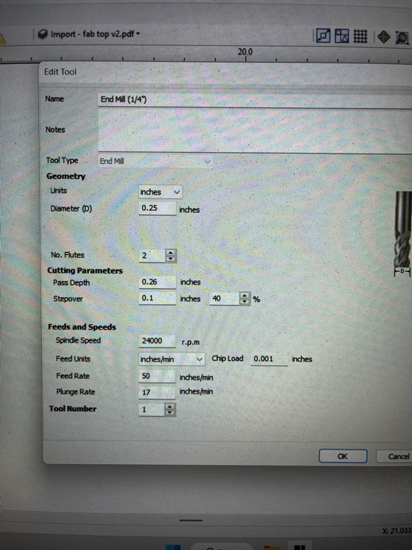
Tool Set Up
Machine Set Up
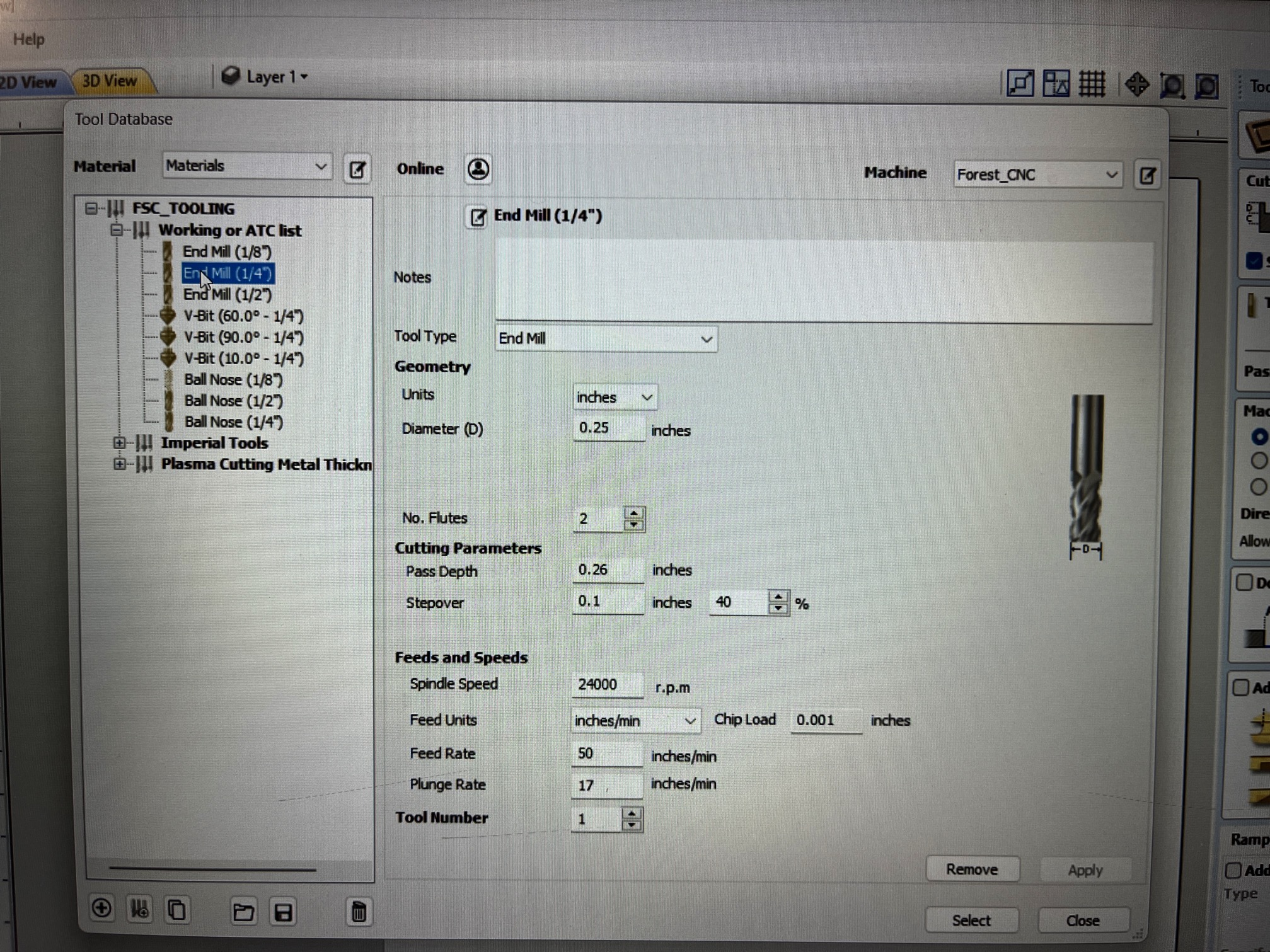
Cutting Bits
This machine can use a wide range of cutting bits, but we used a 1/4" flat downcut mill and a 1/4" flat upcut mill. Both cut a flat-bottomed slot 1/4" wide. The upcut bit pulls upward on the material as it turns, clearing sawdust from the tool path but it can create rough edges. The downcut bit pushes down on the material as it turns, which gives a cleaner edge. We used the downcut bit for the "pocket" in our design, and the upcut mill for the other steps.
Lessons Learned
Our lab safety guidelines can be here.
Individual Assignment
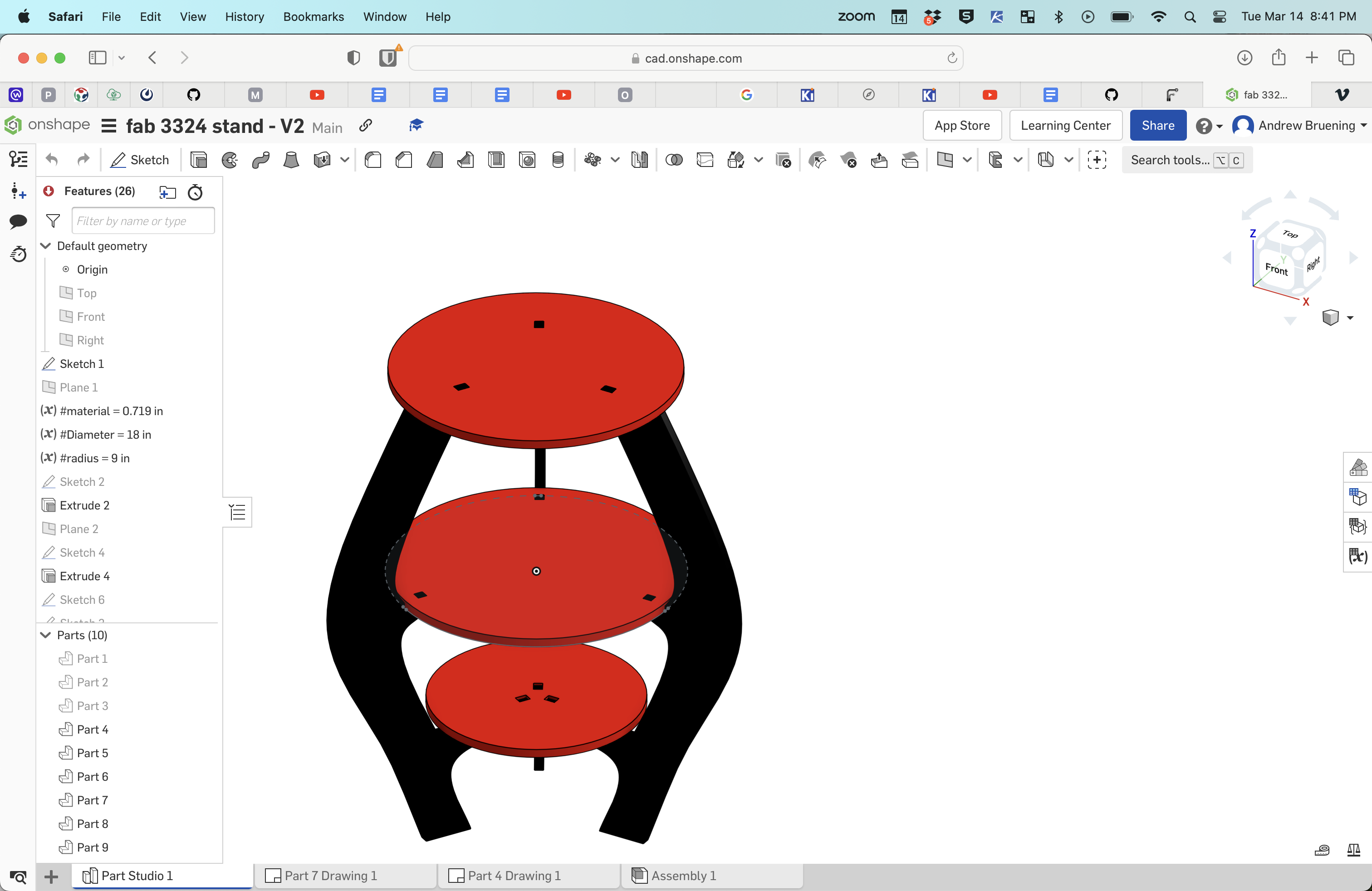
- I wanted to design a display table for my robotics team. I was not sure how I wanted to join the table components but I knew I wanted three shelves and I wanted it to be flat-pack design. The team would need the table to be easily assembled and disassembled to so it could be taken to competition and used in our pit.
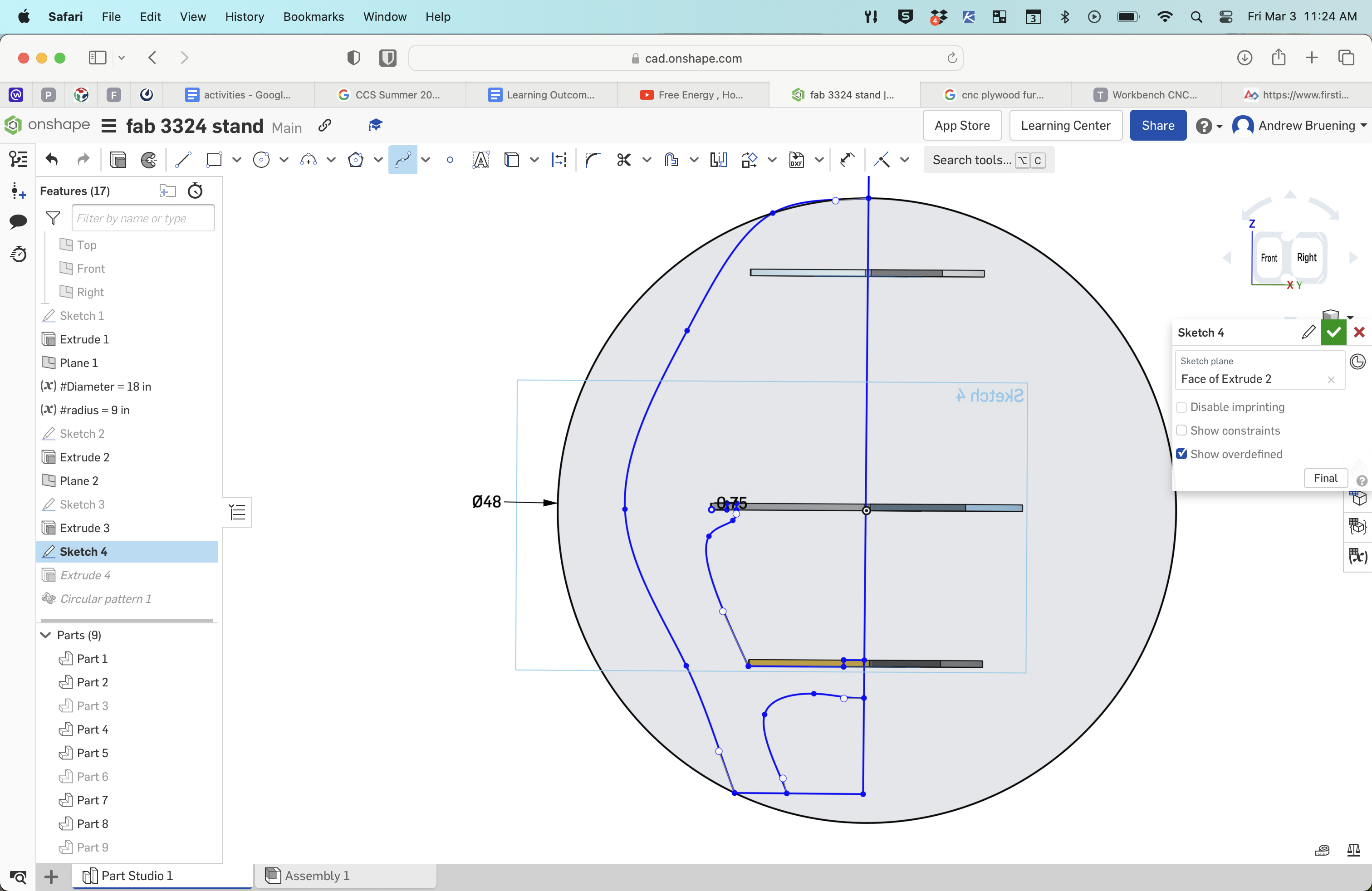
- I wanted the table to have three inter-locking legs to suppor the three shelves. I began the spiral design by making a complete table so I could go back and modify the design to be inter-locking and to meet the requirements for this weeks project.
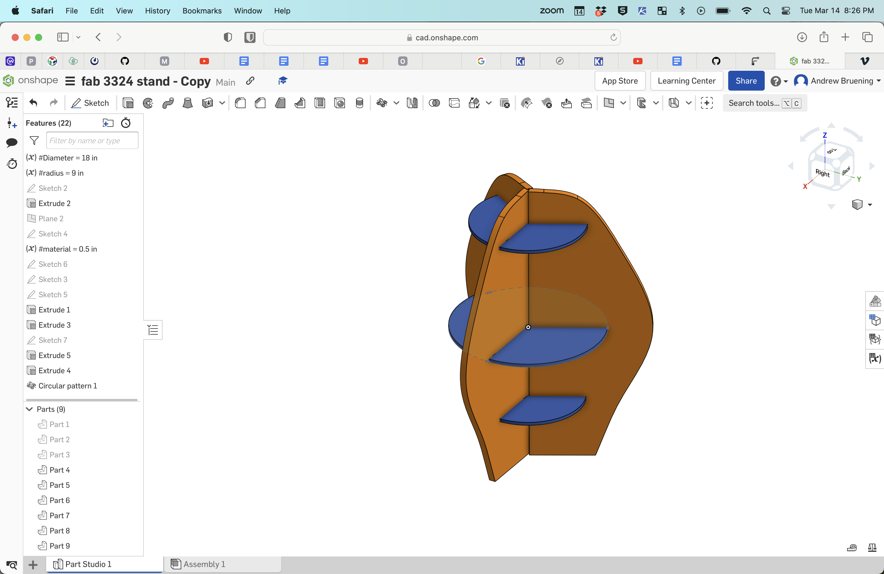
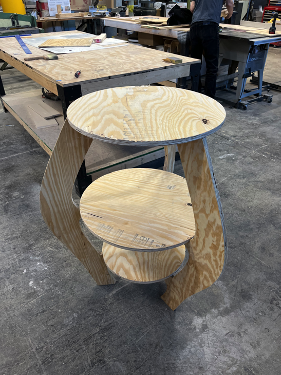
- This first version had some of what I wanted but I was not sure how I was going to connect each of the three pieces of each shelf to the three legs so I decided to make each shelf as one circular shelf that attached snap fit to the legs but also had some style.
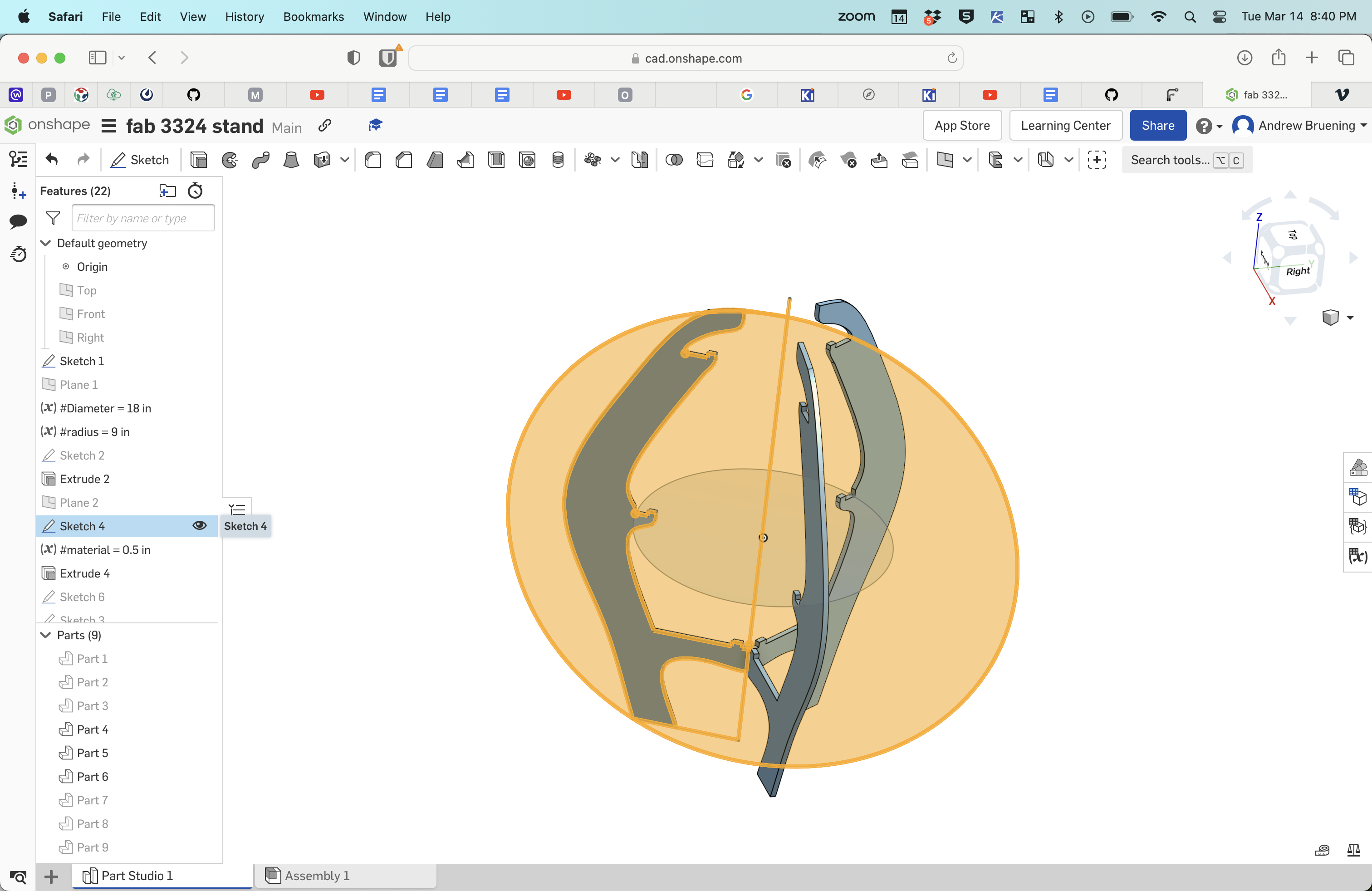
- Version 2 of the table had more style and press fit connections for the three table top sections. But the top of the table would be mostly unusable due to the three legs extending above the top.
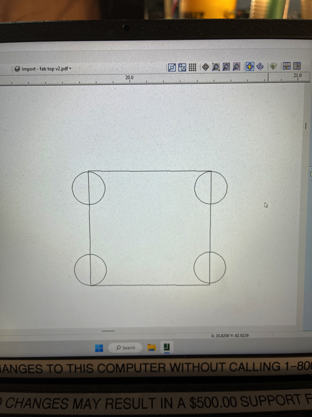
- In order to make the press fit legs fit into the pockets cut in the table tops I had to modify the corners of the tool path. CNC routers cutting inside edge paths will not make square corners so I had to do the "dog bone" corners so the square corners of the leg tabs wouls fit.
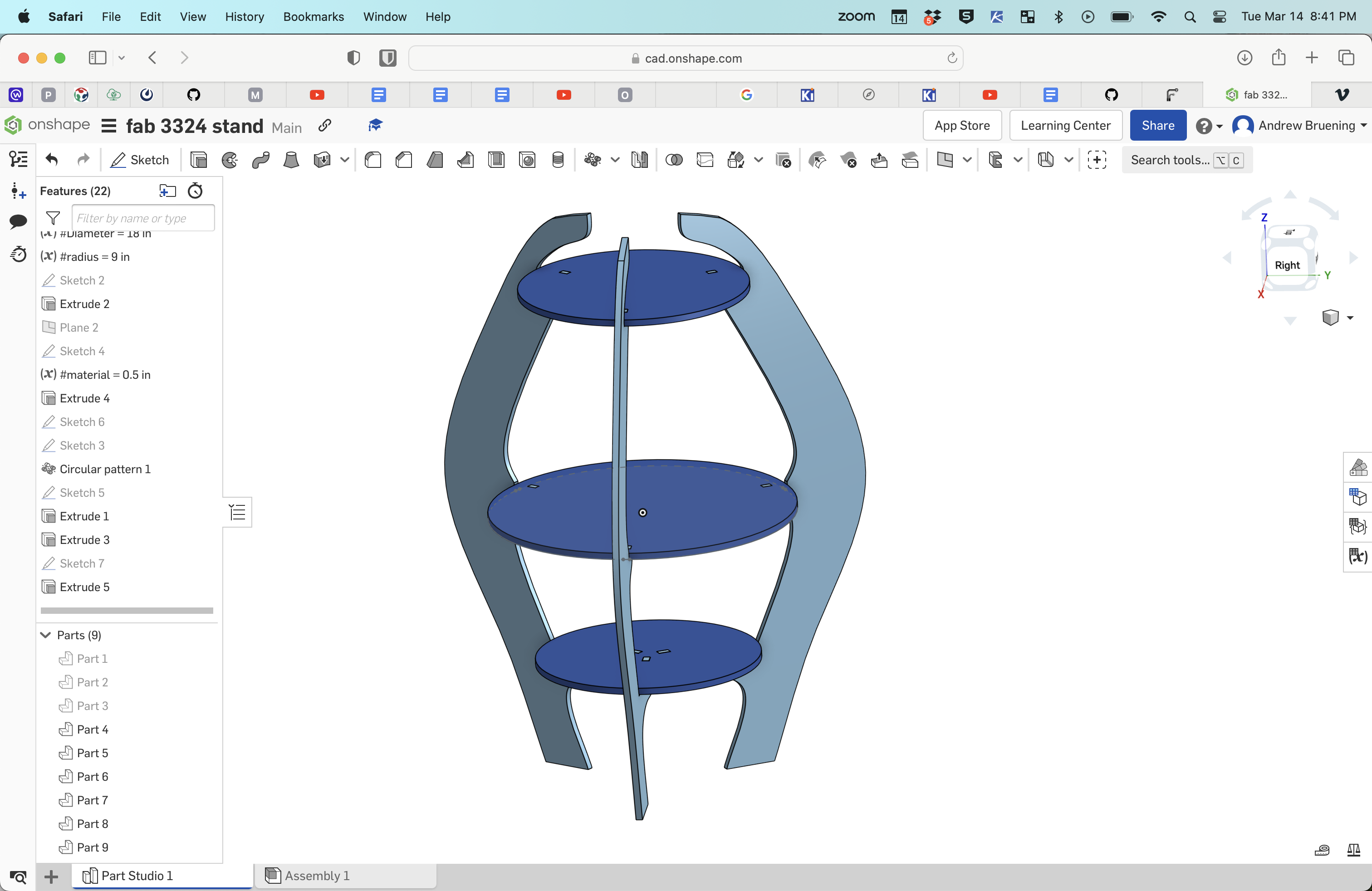
- Ultimately, I modified the leg sketch to end with the top shelf surface.
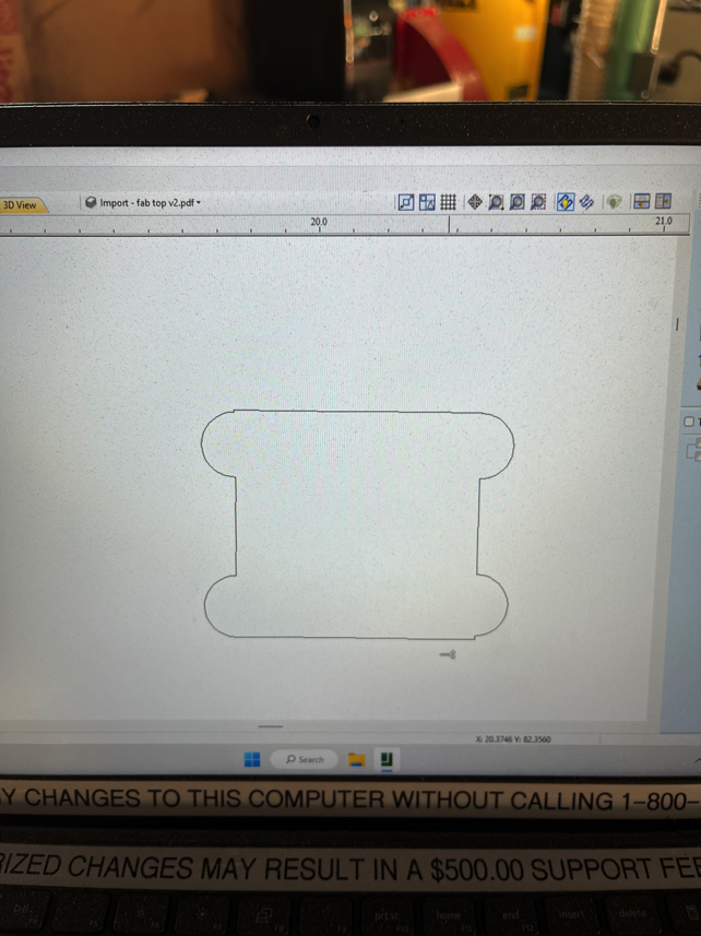
- In order to cut the table pieces on the CNC I had to export each part as a PDF or DXF so it could be imported in to 2DCut Pro.
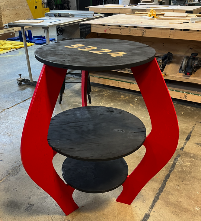
- Finally, painted, laser engraved team number and assembled table ready for team to use.
Design Files
Week 7 table design file