Tasks completed
Purchased all components for final project
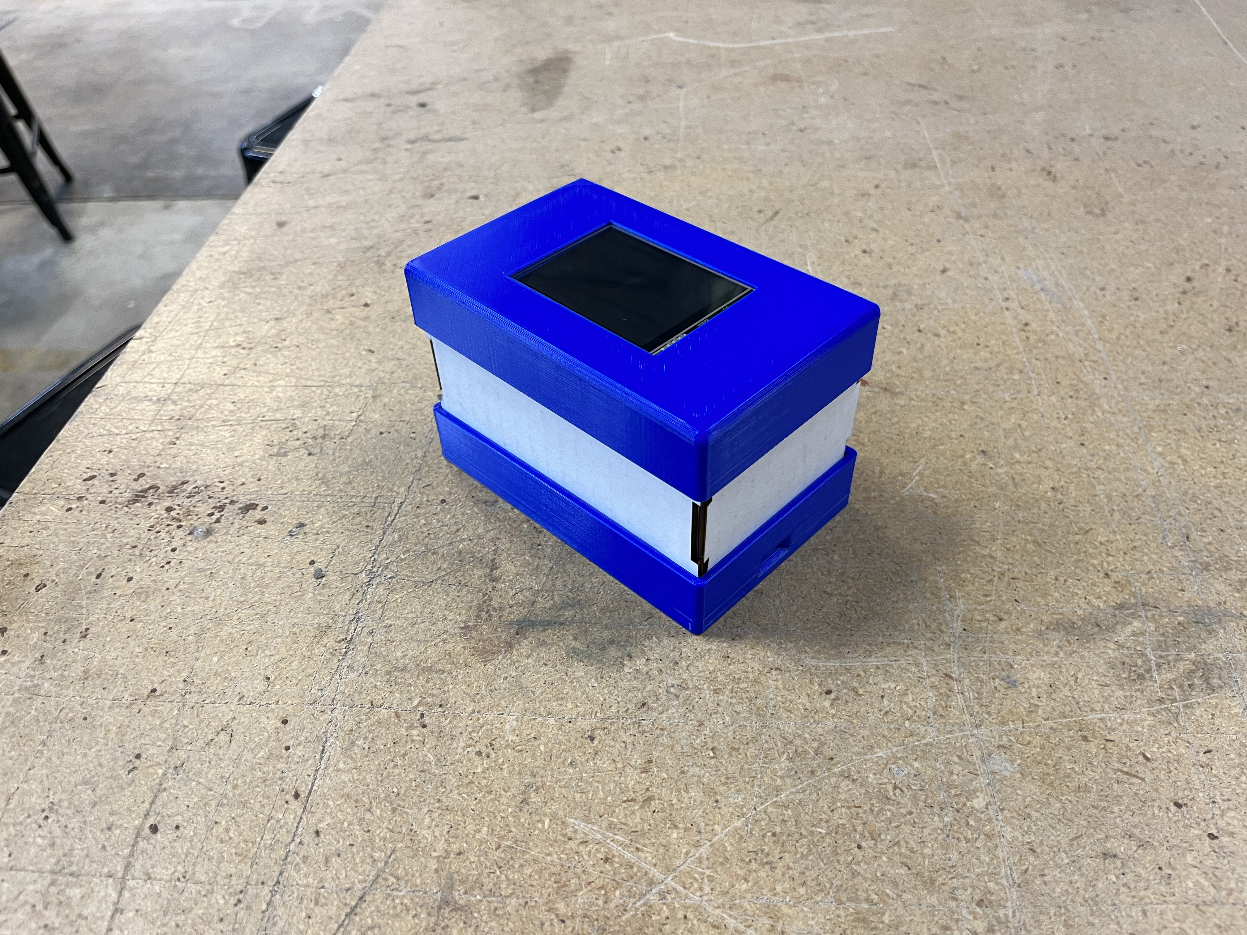
Designed and 3d printed base and top of device
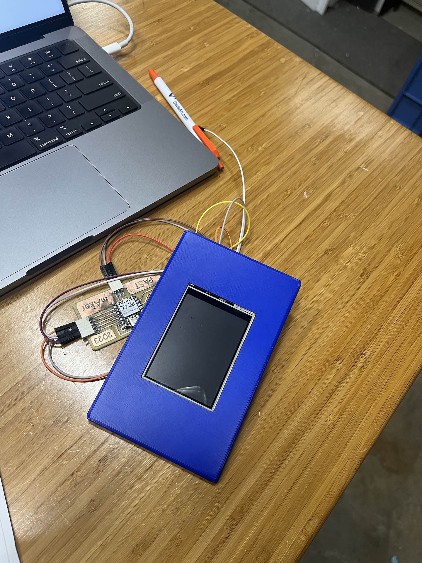
Prototyping and Testing for Final Project
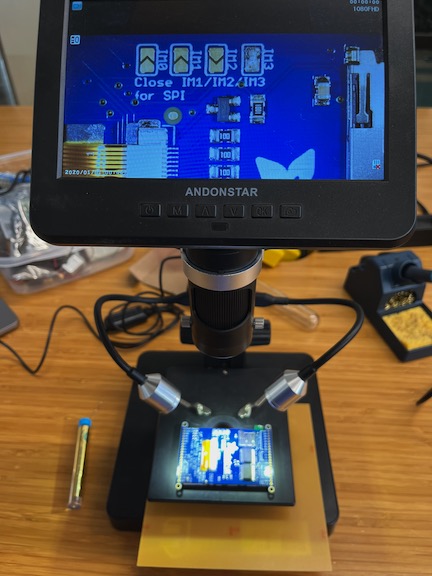
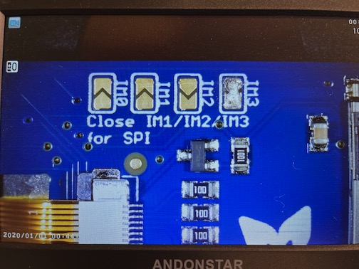
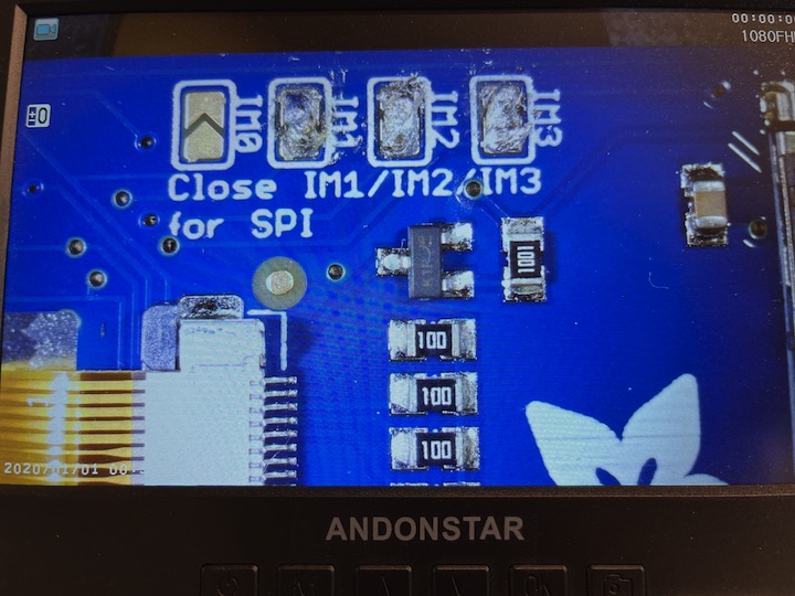
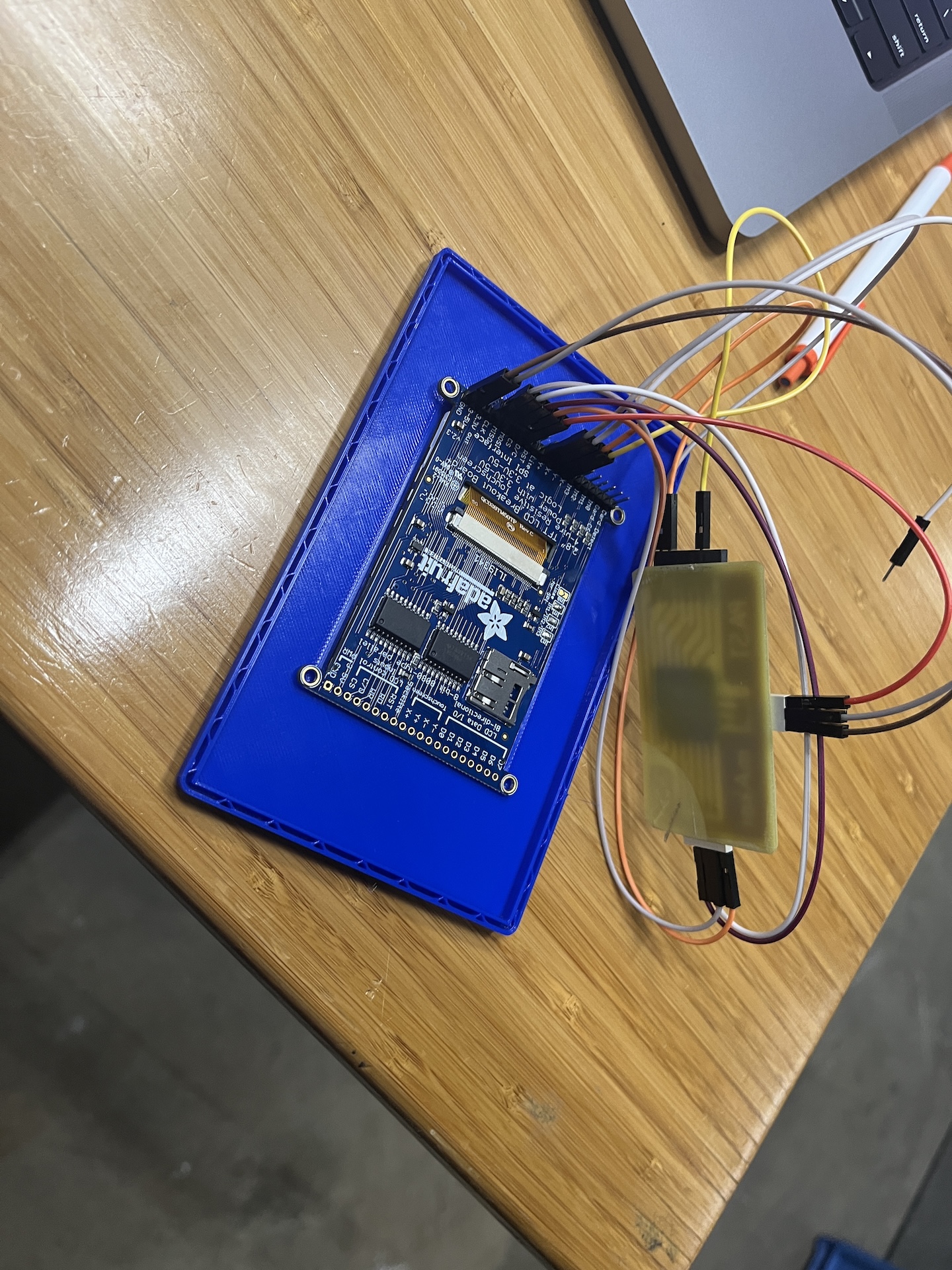
The Adafruit 2.8" TFT LCD Breakout board has both 8-bit and SPI interfaces.
I am using the SPI interface so I had to make sure that the board know which pins to listen to. So in order for the board to listen to the SPI pins I needed to solder closed the IMx jumpers on the back of the PCB. Using a soldering iron, I melted solder to close the three jumpers indicated IM1 IM2 and IM3 (do not solder closed IM0!). The photos below show before and after closing the jumpers.
Display Test
Arduino Example Code for Graphics Test
/***************************************************
This is our GFX example for the Adafruit ILI9341 Breakout and Shield
----> http://www.adafruit.com/products/1651


Written by Limor Fried/Ladyada for Adafruit Industries.
MIT license, all text above must be included in any redistribution
****************************************************/


#include "SPI.h"
#include "Adafruit_GFX.h"
#include "Adafruit_ILI9341.h"

// For the Adafruit shield, these are the default.
#define TFT_DC D6
#define TFT_CS D7

// Use hardware SPI (on Uno, #13, #12, #11) and the above for CS/DC
Adafruit_ILI9341 tft = Adafruit_ILI9341(TFT_CS, TFT_DC);
// If using the breakout, change pins as desired
//Adafruit_ILI9341 tft = Adafruit_ILI9341(TFT_CS, TFT_DC, TFT_MOSI, TFT_CLK, TFT_RST, TFT_MISO);

// For RP2040 - use pin numbers in the form PIN_Dx where Dx is the RP2040 pin designation
#define TFT_MISO D9
#define TFT_MOSI D10
#define TFT_SCLK D8
#define YP A0
#define XP D6
#define YM D1
#define XM A3


void setup() {
Serial.begin(9600);
Serial.println("ILI9341 Test!");

tft.begin();

// read diagnostics (optional but can help debug problems)
uint8_t x = tft.readcommand8(ILI9341_RDMODE);
Serial.print("Display Power Mode: 0x"); Serial.println(x, HEX);
x = tft.readcommand8(ILI9341_RDMADCTL);
Serial.print("MADCTL Mode: 0x"); Serial.println(x, HEX);
x = tft.readcommand8(ILI9341_RDPIXFMT);
Serial.print("Pixel Format: 0x"); Serial.println(x, HEX);
x = tft.readcommand8(ILI9341_RDIMGFMT);
Serial.print("Image Format: 0x"); Serial.println(x, HEX);
x = tft.readcommand8(ILI9341_RDSELFDIAG);
Serial.print("Self Diagnostic: 0x"); Serial.println(x, HEX);

Serial.println(F("Benchmark                Time (microseconds)"));
delay(10);
Serial.print(F("Screen fill              "));
Serial.println(testFillScreen());
delay(500);

Serial.print(F("Text                     "));
Serial.println(testText());
delay(3000);

Serial.print(F("Lines                    "));
Serial.println(testLines(ILI9341_CYAN));
delay(500);

Serial.print(F("Horiz/Vert Lines         "));
Serial.println(testFastLines(ILI9341_RED, ILI9341_BLUE));
delay(500);

Serial.print(F("Rectangles (outline)     "));
Serial.println(testRects(ILI9341_GREEN));
delay(500);

Serial.print(F("Rectangles (filled)      "));
Serial.println(testFilledRects(ILI9341_YELLOW, ILI9341_MAGENTA));
delay(500);

Serial.print(F("Circles (filled)         "));
Serial.println(testFilledCircles(10, ILI9341_MAGENTA));

Serial.print(F("Circles (outline)        "));
Serial.println(testCircles(10, ILI9341_WHITE));
delay(500);

Serial.print(F("Triangles (outline)      "));
Serial.println(testTriangles());
delay(500);

Serial.print(F("Triangles (filled)       "));
Serial.println(testFilledTriangles());
delay(500);

Serial.print(F("Rounded rects (outline)  "));
Serial.println(testRoundRects());
delay(500);

Serial.print(F("Rounded rects (filled)   "));
Serial.println(testFilledRoundRects());
delay(500);

Serial.println(F("Done!"));

}


void loop(void) {
for(uint8_t rotation=0; rotation<4; rotation++) {
  tft.setRotation(rotation);
  testText();
  delay(1000);
}
}

unsigned long testFillScreen() {
unsigned long start = micros();
tft.fillScreen(ILI9341_BLACK);
yield();
tft.fillScreen(ILI9341_RED);
yield();
tft.fillScreen(ILI9341_GREEN);
yield();
tft.fillScreen(ILI9341_BLUE);
yield();
tft.fillScreen(ILI9341_BLACK);
yield();
return micros() - start;
}

unsigned long testText() {
tft.fillScreen(ILI9341_BLACK);
unsigned long start = micros();
tft.setCursor(0, 0);
tft.setTextColor(ILI9341_WHITE);  tft.setTextSize(1);
tft.println("Hello World!");
tft.setTextColor(ILI9341_YELLOW); tft.setTextSize(2);
tft.println(1234.56);
tft.setTextColor(ILI9341_RED);    tft.setTextSize(3);
tft.println(0xDEADBEEF, HEX);
tft.println();
tft.setTextColor(ILI9341_GREEN);
tft.setTextSize(5);
tft.println("Groop");
tft.setTextSize(2);
tft.println("I implore thee,");
tft.setTextSize(1);
tft.println("my foonting turlingdromes.");
tft.println("And hooptiously drangle me");
tft.println("with crinkly bindlewurdles,");
tft.println("Or I will rend thee");
tft.println("in the gobberwarts");
tft.println("with my blurglecruncheon,");
tft.println("see if I don't!");
return micros() - start;
}

unsigned long testLines(uint16_t color) {
unsigned long start, t;
int           x1, y1, x2, y2,
              w = tft.width(),
              h = tft.height();

tft.fillScreen(ILI9341_BLACK);
yield();

x1 = y1 = 0;
y2    = h - 1;
start = micros();
for(x2=0; x20; i-=6) {
  i2    = i / 2;
  start = micros();
  tft.fillRect(cx-i2, cy-i2, i, i, color1);
  t    += micros() - start;
  // Outlines are not included in timing results
  tft.drawRect(cx-i2, cy-i2, i, i, color2);
  yield();
}

return t;
}

unsigned long testFilledCircles(uint8_t radius, uint16_t color) {
unsigned long start;
int x, y, w = tft.width(), h = tft.height(), r2 = radius * 2;

tft.fillScreen(ILI9341_BLACK);
start = micros();
for(x=radius; x10; i-=5) {
  start = micros();
  tft.fillTriangle(cx, cy - i, cx - i, cy + i, cx + i, cy + i,
    tft.color565(0, i*10, i*10));
  t += micros() - start;
  tft.drawTriangle(cx, cy - i, cx - i, cy + i, cx + i, cy + i,
    tft.color565(i*10, i*10, 0));
  yield();
}

return t;
}

unsigned long testRoundRects() {
unsigned long start;
int           w, i, i2,
              cx = tft.width()  / 2 - 1,
              cy = tft.height() / 2 - 1;

tft.fillScreen(ILI9341_BLACK);
w     = min(tft.width(), tft.height());
start = micros();
for(i=0; i20; i-=6) {
  i2 = i / 2;
  tft.fillRoundRect(cx-i2, cy-i2, i, i, i/8, tft.color565(0, i, 0));
  yield();
}

return micros() - start;
}
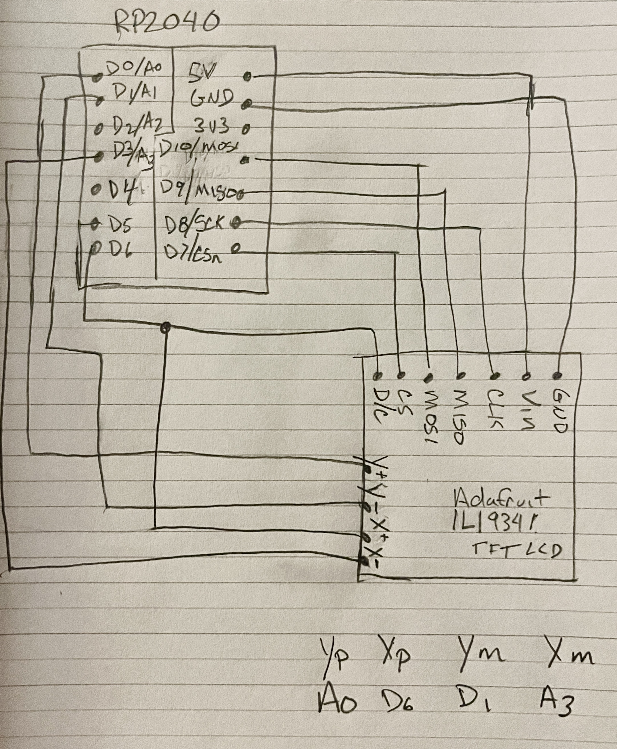
Wire Diagram
Wiring for the Adafruit ILI9341
After reading the documentation for the Adafruit Color TFT Touchscreen Breakout I have determined that the wiring will go as you see below. Wiring up the display in SPI mode is easier than 8-bit mode because there are fewer wire connections to worry about. However, its slower than parallel 8-bit mode because you have to send each bit one at a time instead of 8-bits at a time.
- Power pins 3-5V Vin connects to the 5V pin
- GND connects to ground
- CLK connects to SPI clock. On Seeed Xiao RP2040 that is D8/SCK
- MISO connects to SPI MISO. On Seeed Xiao RP2040 that is D9/MISO
- MOSI connects to SPI MOSI or D10
- CS connects to SPI D7/CSn
- D/C connects to the SPI data/command pin. I set this up as D6 but could be another digital pin
Touch Test
Neopixel test on Arduino
After testing the screen and Neopixel on Arduino I wanted to make sure that I could run the same code examples on a board I created. I used the test board from Week 8 but for some reason I am not able to get the touch screen to display the graphics test.
I have been able to print a draft version of the top of the device to make sure the screen fits nicely in the design.
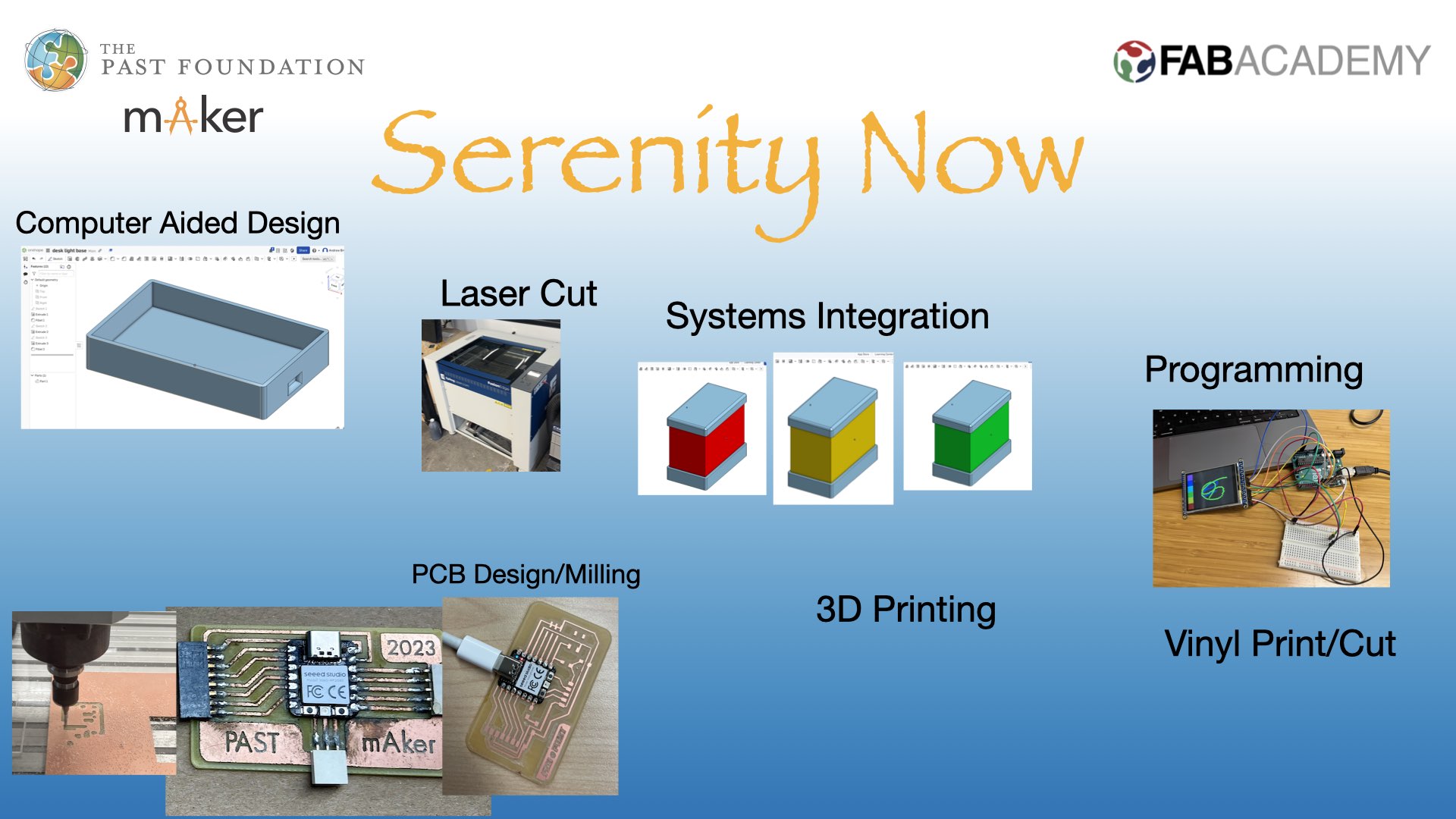
Draft of Slide for Final Project Presentation
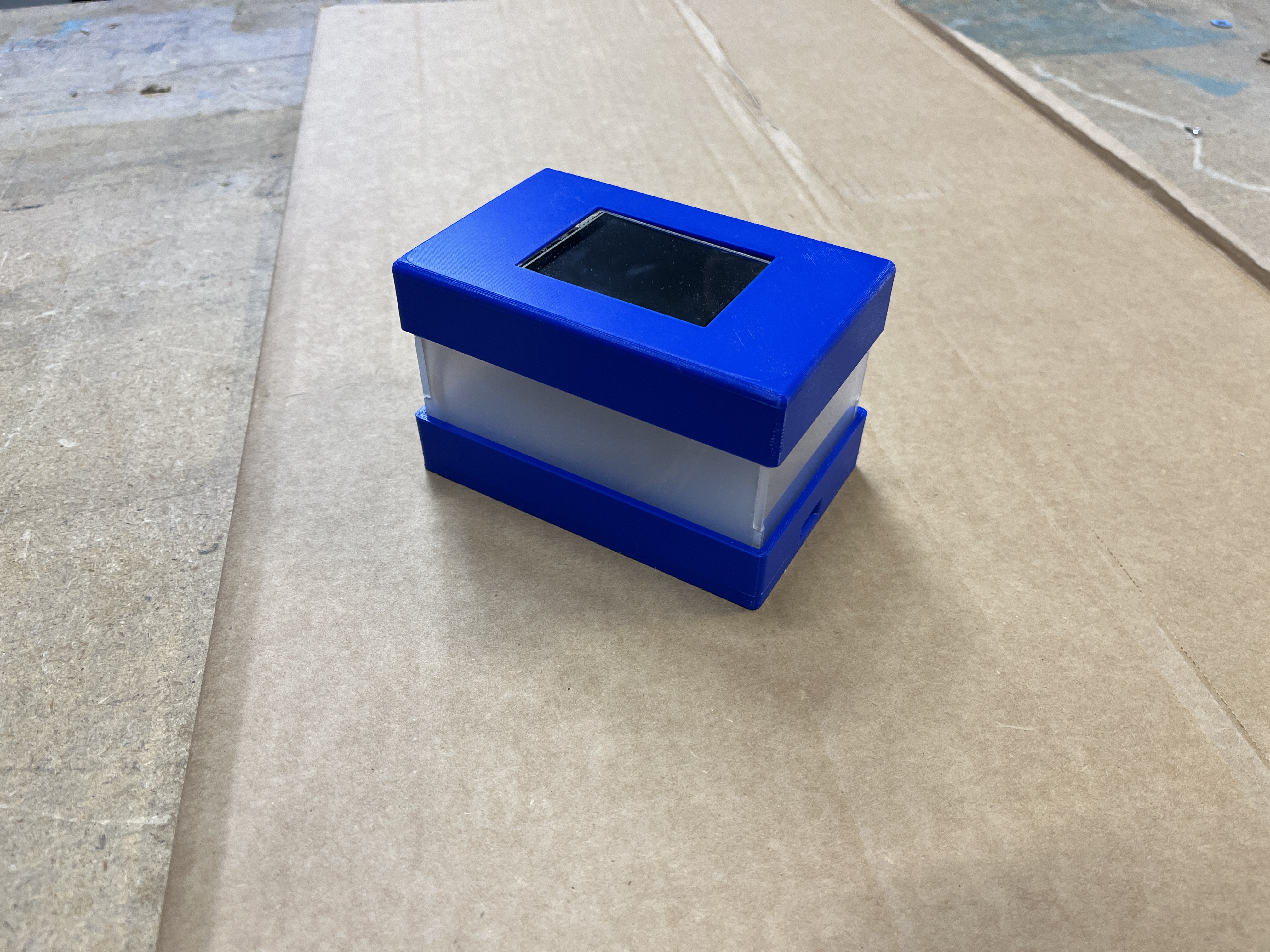
Side panels are designed and laser cut but I cut them out of cardboard first to make sure they fit well.
After testing the cardboard sides I was able to cut the final version out of acrylic.
PROGRESS
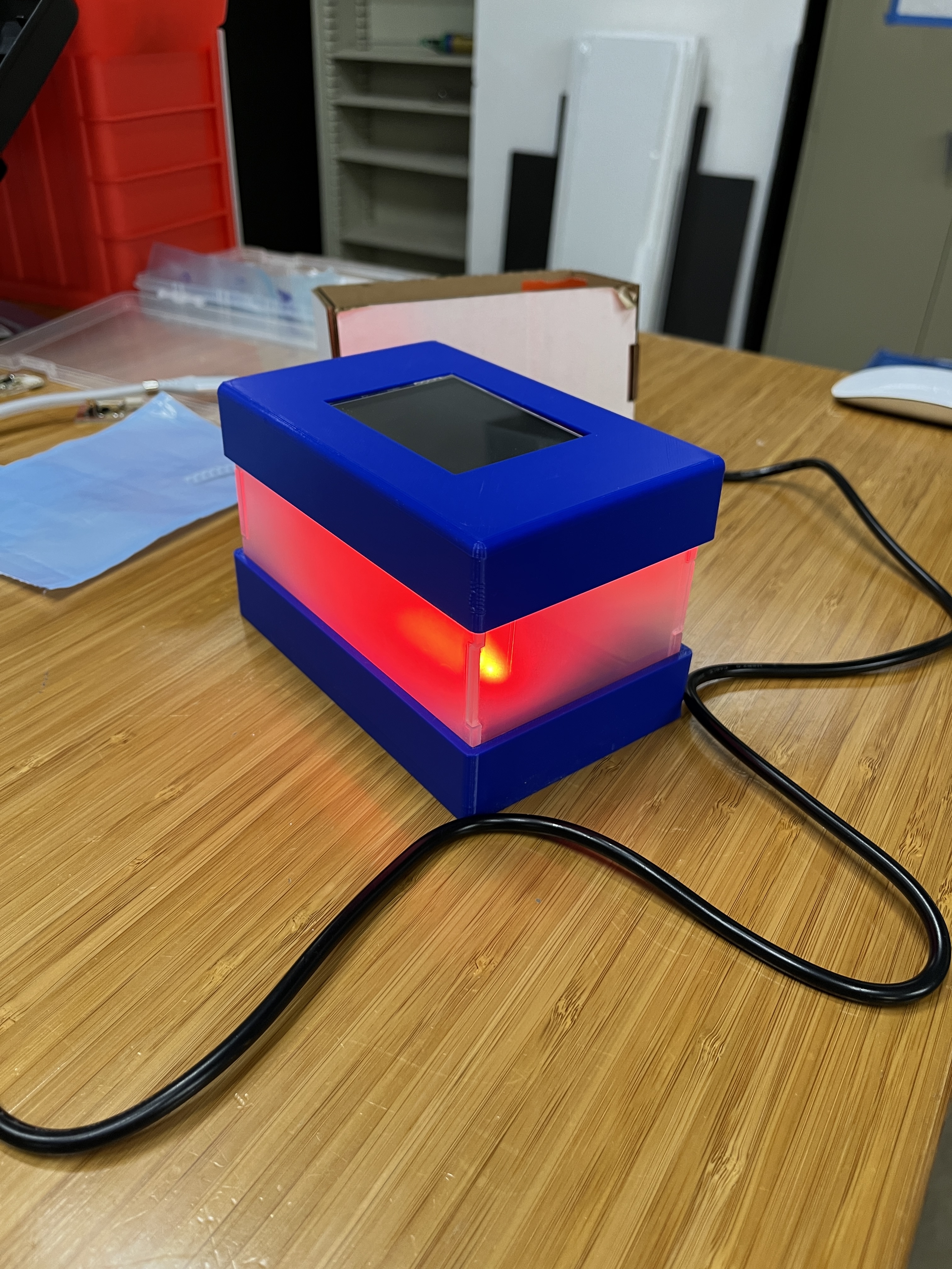
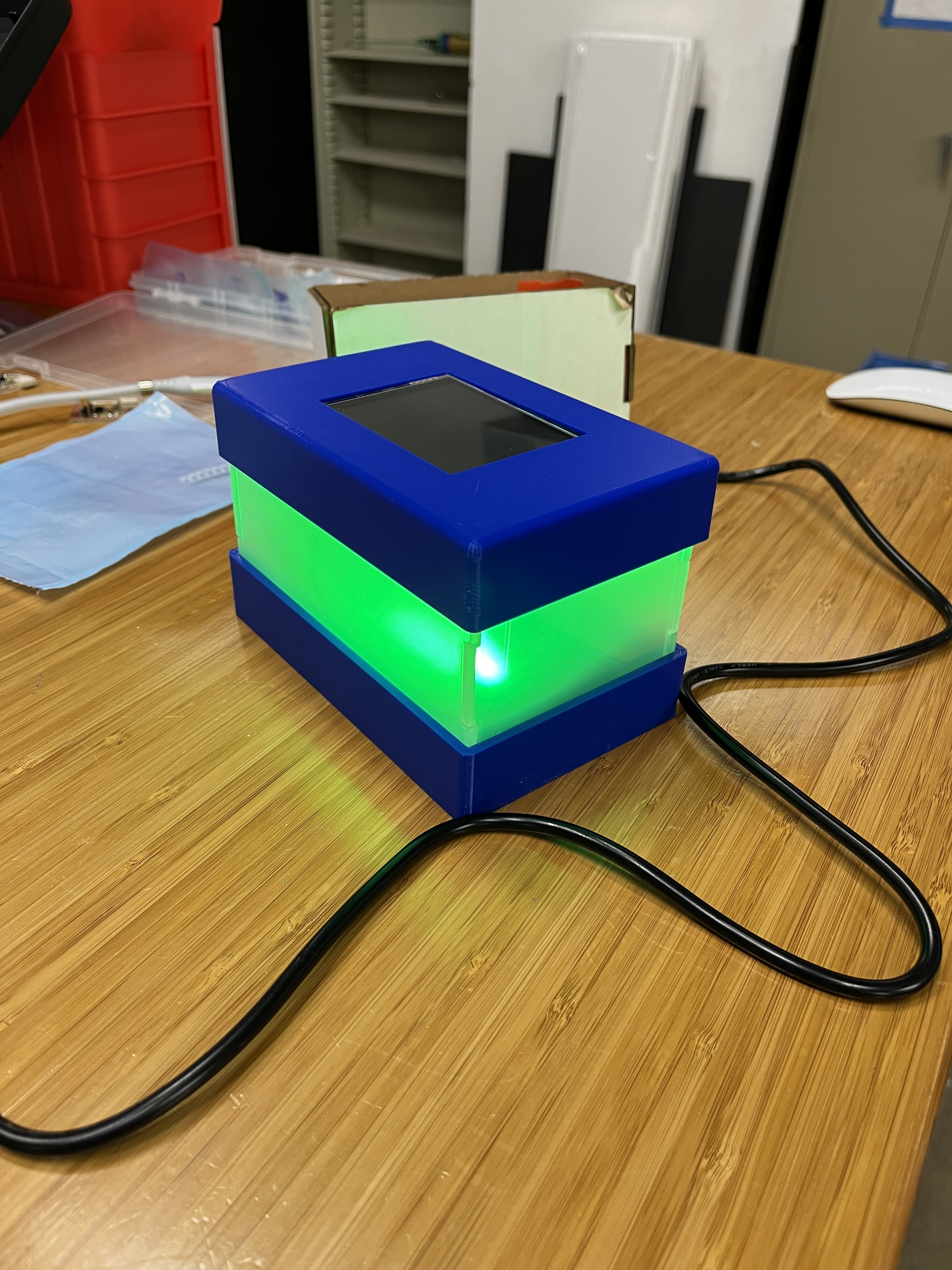
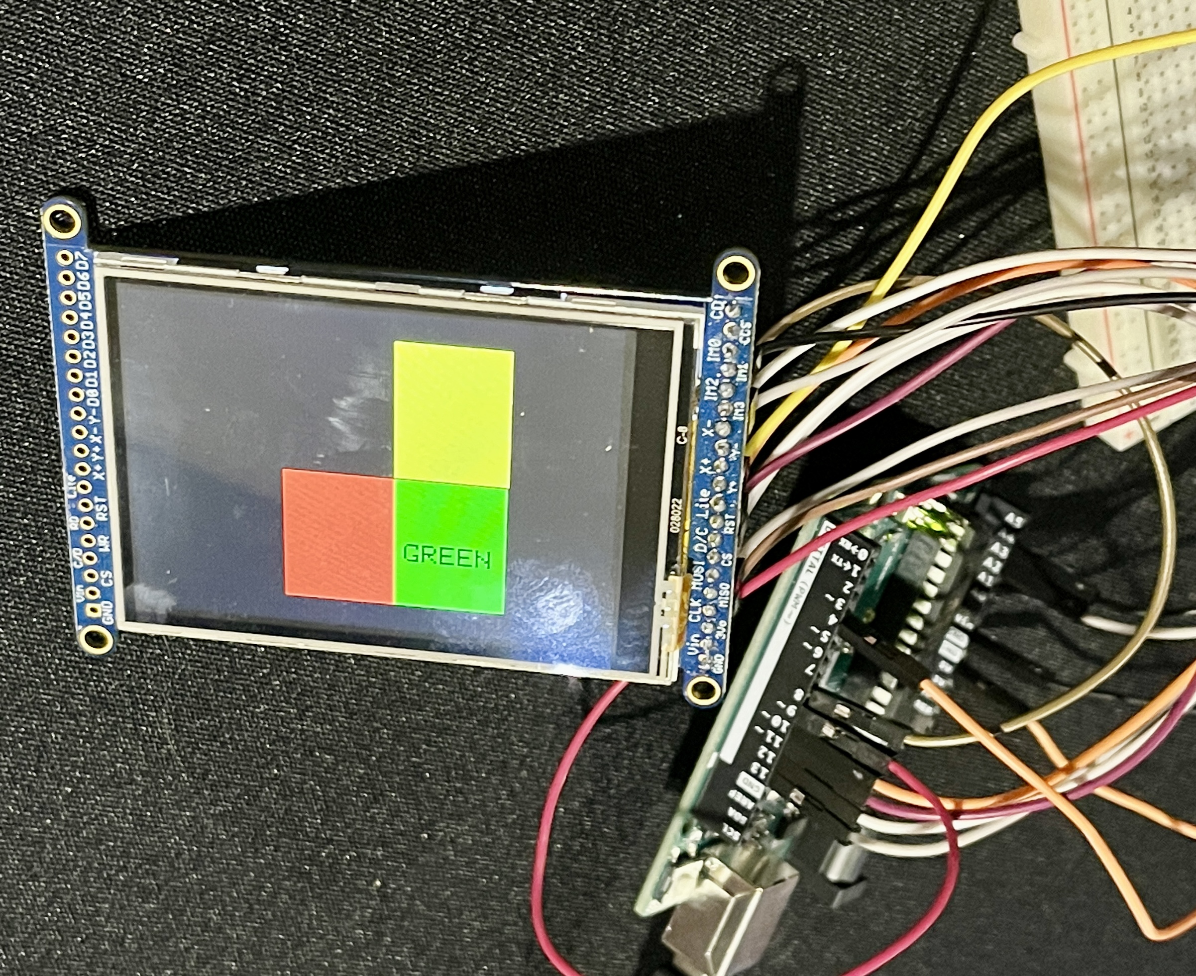
I was finally able to create three buttons on the display, one green, red and one yellow for the different states of avaiability. Next is to make the neopixel turn on when the color button is pressed.
**UPDATE**
Task left to complete
I still need to design and vinyl cut the final product decals but that will not take long.
**UPDATE**Freshly designed vinyl decal to be printed and cut.

I still need to test the neopixel on the board I have designed. NeoPixel Library
Need to finish the code for the GUI with the three color buttons for each state of "availability"
What has worked and what has not
Testing of the neopixel and LCD display was successful when connected to Arduino but so far no luck testing on board i created
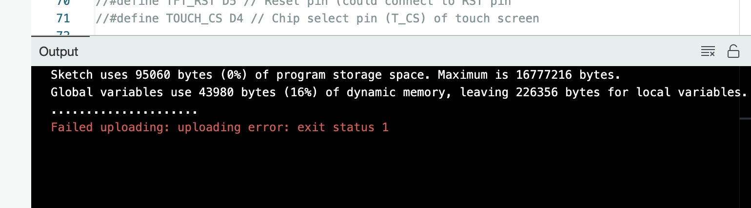
I am now having trouble connecting my RP2040 board I created to my computer and Arduino. Sometimes it will connect via USB-C and other times the board does not register and will not let me connect and upload. Other times it "connects" but when I try to upload it gives me a message that 0% program storage space has been used. See image
 CAD design of base and sides has gone really well. No major issues with this portion of the project.
Questions still to be resolved
At this point I am not sure how to make the LCD screen work with my board. It rus the example code just fine with connected to Arduino but I have not had any luck when connected to my Seeed Xiao Rp2040.
What will happen when…
When this is all complete the device will sit on my desk and help others know when I am available or not.
What have you learned
I have realized that I still have quite a bit to learn with respect to coding. I have a general understanding of what it should all do logically but when it comes to the actual coding part I just need more practice.
Another thing I take away from this experience is that even though I chose to do an entirely new project at the last minute I needed to develop a better work plan/timeline. I say this to my students all the time that they need to plan it all out before getting started but this time I did not follow my own advice...sadly.