My Final Project Ideas
I have several ideas for a final project that involve making things around our Innovation Lab. I have considered making a robot arm that could eventually be use as part of our summer camps for middle school students or an automated vertical garden that would be modeled after the Farmbot. Another idea involves creating an interactive sound wall that serves as part of a tour of PAST. This sound wall would be made up of 2D images and 3D modles that a visitor cound interact with and then hear a description or story about some aspect of our work. This could include voice recordings of students that participate in our programs or parents of students or even community partners that support our programs.
Research
Modeling of Final Project Concepts
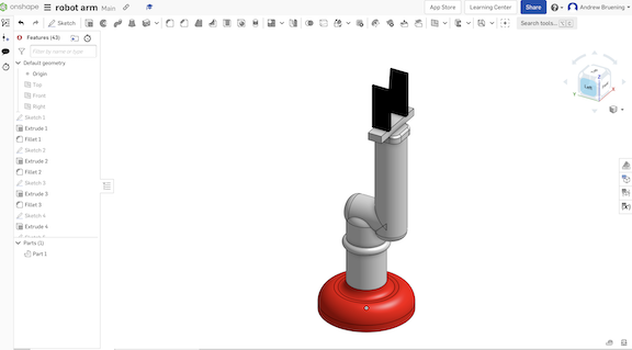
Below is a rough concept of robotic arm in OnShape. The actual arm would have more degrees of motion than this simple model
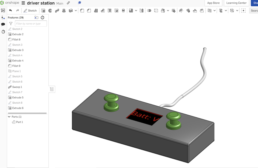
At PAST we are creating STEM kits for middle school students and one of the kits is an underwater ROV. For the ROV I want to create driver/operator stations for the students so the can focus on the design and build of the ROV and not have to worry about how they will operate the vehicle.
One idea is for my robotics team. We have students sign in for attendance hours in order to go to competition. We have been using an iPad for sign in but we have found that some students will sign in/out for their friends and "pad" thier hours. So, I want to design a fingerprint scanner sign in system so ensure that hours are more accurate and legit. I do not have a sketch of this yet.
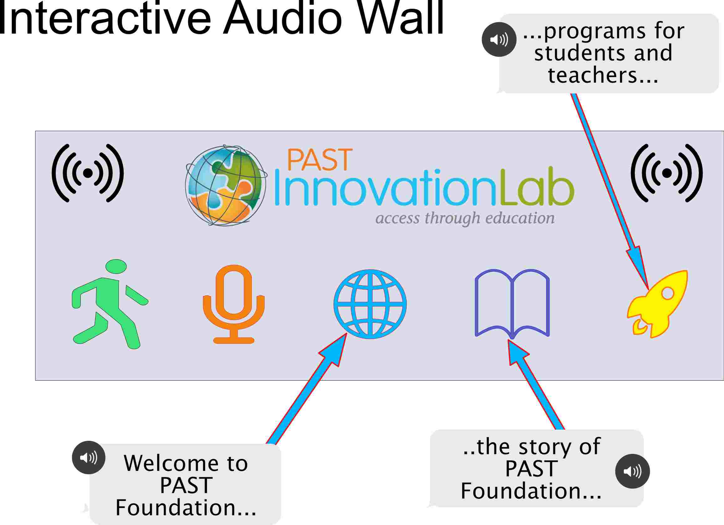
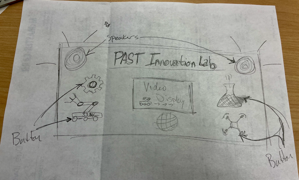
Concept drawing of interactive sound wall/board/display. Guests of PAST Foundation can interact with the wall/display by pressing one of the objects then an audio recording will play describing or explaining what that object represents. For example the 'Globe' in the middle could be the voice our PAST CEO/president explaining what PAST is all about. Or the other objects will have voices of student/teacher participants talking about their experiences with PAST.
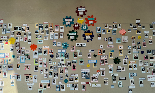
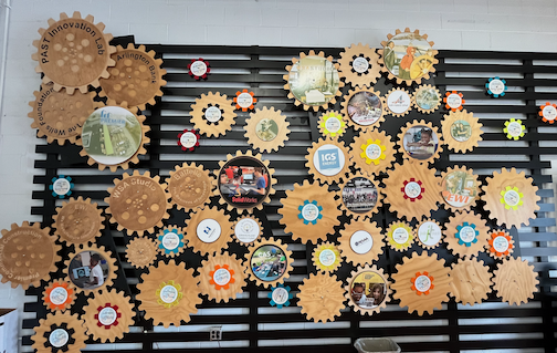
Students at PAST complete interships and capstone projects with our community partners and we currently have a static display of images and the locations of their projects but we want something more interactive. I would like to see an interactive video display but we can start with an interacive audio wall where visitors and guests can press an icon to hear about a student experience
Final Project
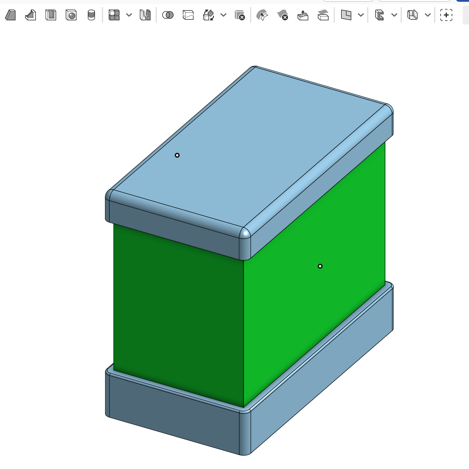
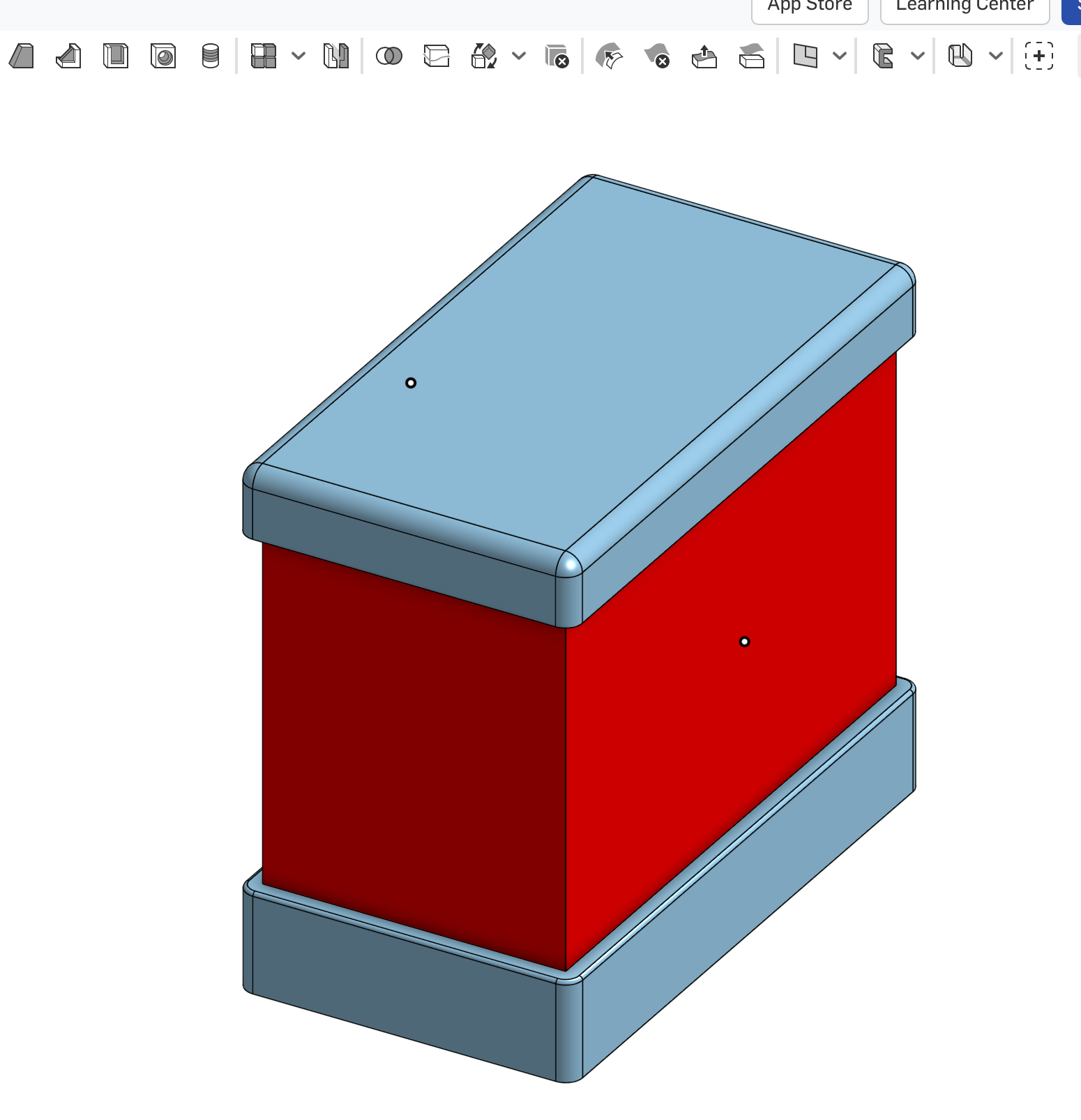
I have decided to design and build a "do not disturb" light for my office desk. We have an open office and as a result colleagues tend to walk up and start talking to each other even if we are busy working or on a Zoom meeting. So, I have decided to design my own version for the office. I know there are several off the shelf products available but I want design my own.
Examples available online
I have been thinking about how I want the lamp to work. Some ideas include:
- Touch screen to change busy status.
- Gyro sensor so when the lamp is rotated to a specific position it will change color to indicate busy status.
- Wireless and sycronous with my Google calendar for Zoom meetings.
- Connectivity to others in the office so if more than one of us are on the same Zoom it can indicate that we are both busy.
Materials, Fabrication and Design
- Fabrication tools
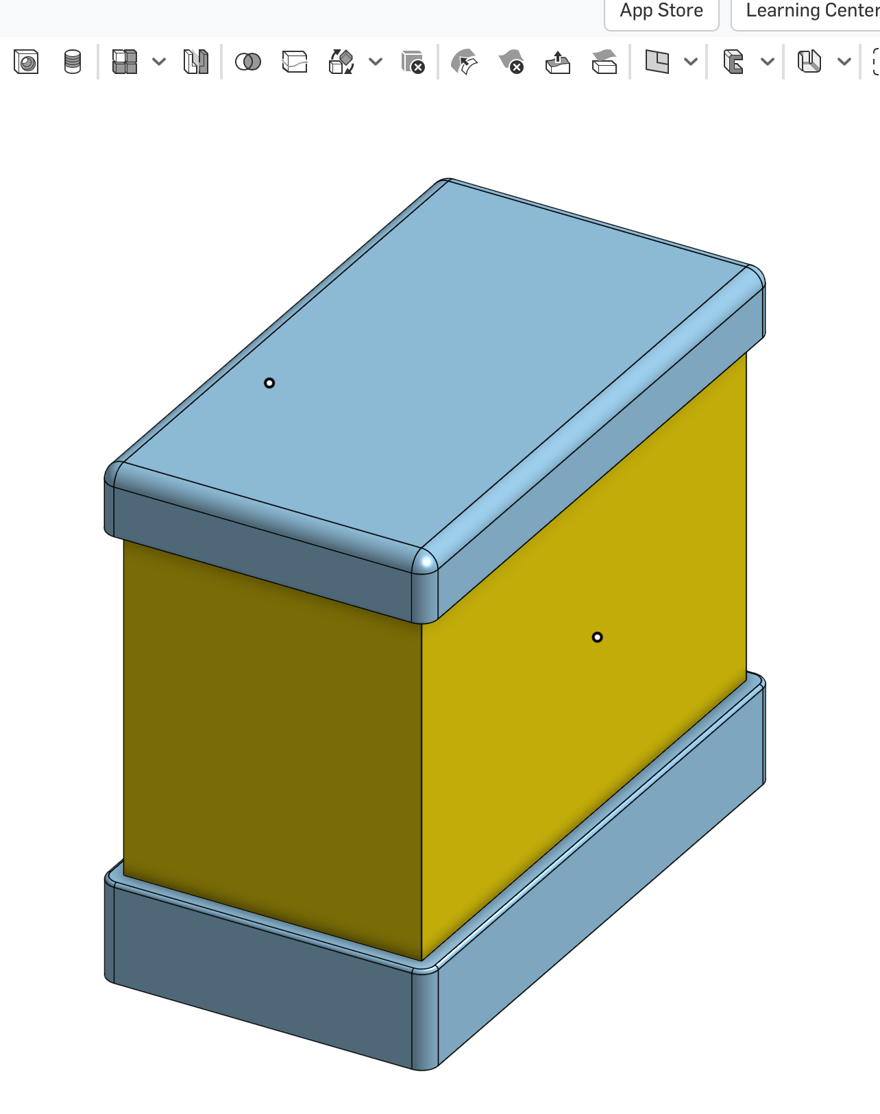
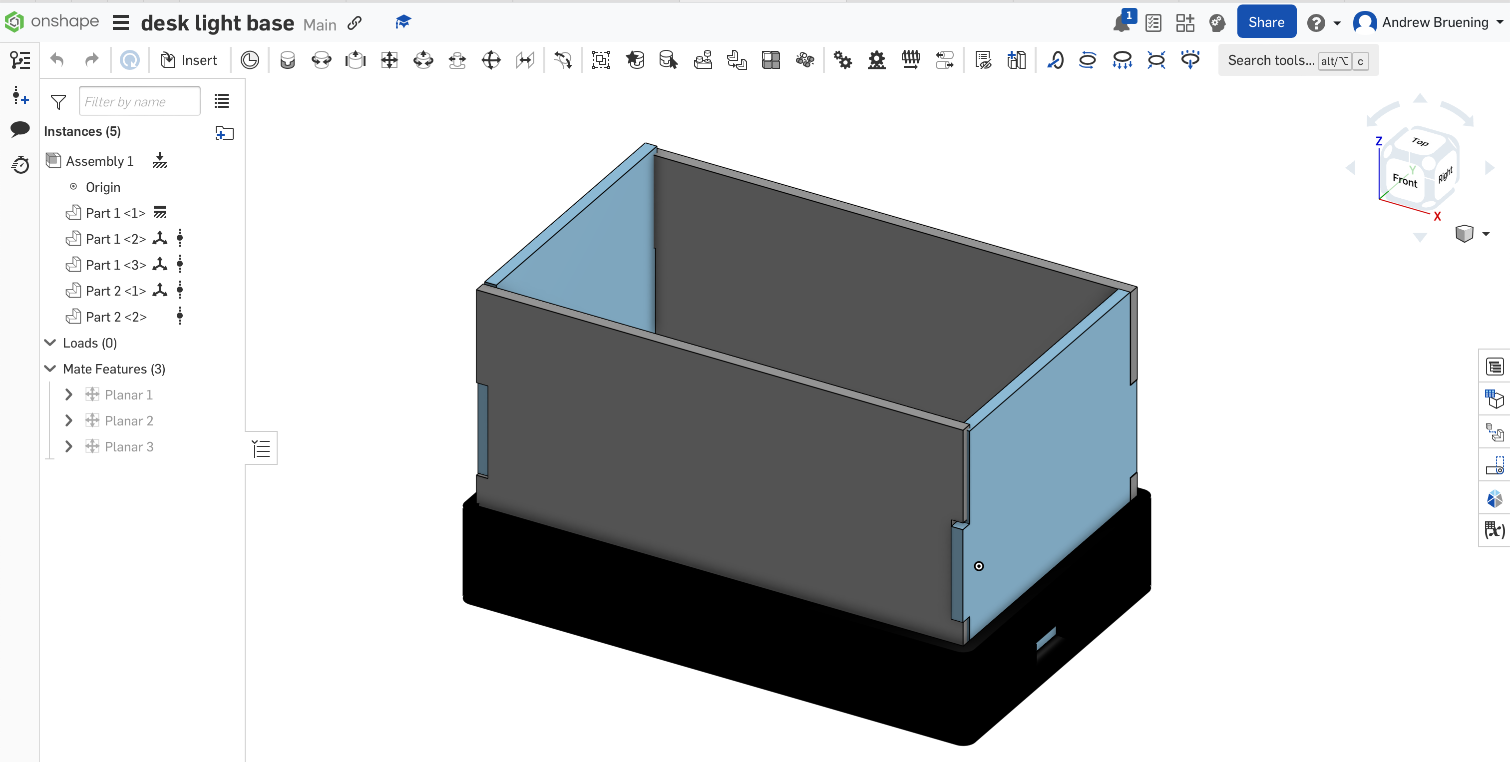
- 3D printed based and top
- Laser Cut acrylic
- CNC milled PCB
- More to follow.....
- Materials
- FDM filament
- Frosted acrylic
- Adafruit 2.8" TFT LCD Breakout board. 4-wire resistive touchscreen.
- RGBW addressable LED module.
Prototyping and Testing for Final Project
The Adafruit 2.8" TFT LCD Breakout board has both 8-bit and SPI interfaces.
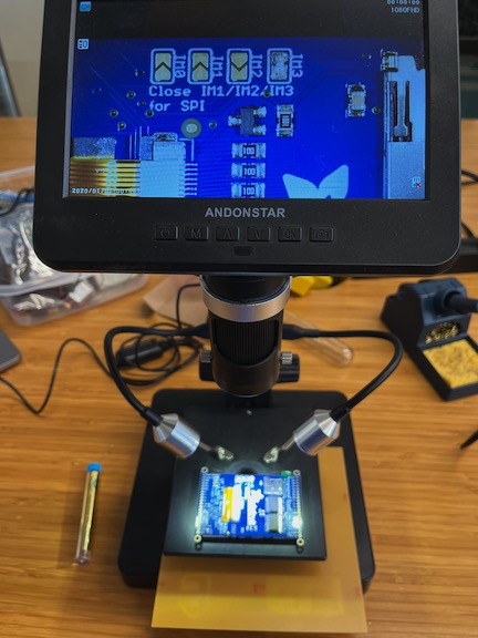
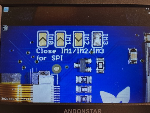
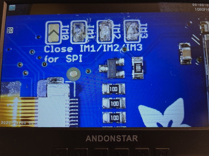
I am using the SPI interface so I had to make sure that the board know which pins to listen to. So in order for the board to listen to the SPI pins I needed to solder closed the IMx jumpers on the back of the PCB. Using a soldering iron, I melted solder to close the three jumpers indicated IM1 IM2 and IM3 (do not solder closed IM0!). The photos below show before and after closing the jumpers.
Arduino Example Code for Graphics Test
  /***************************************************
  This is our GFX example for the Adafruit ILI9341 Breakout and Shield
  ----> http://www.adafruit.com/products/1651


  Written by Limor Fried/Ladyada for Adafruit Industries.
  MIT license, all text above must be included in any redistribution
 ****************************************************/


#include "SPI.h"
#include "Adafruit_GFX.h"
#include "Adafruit_ILI9341.h"

// For the Adafruit shield, these are the default.
#define TFT_DC D6
#define TFT_CS D7

// Use hardware SPI (on Uno, #13, #12, #11) and the above for CS/DC
Adafruit_ILI9341 tft = Adafruit_ILI9341(TFT_CS, TFT_DC);
// If using the breakout, change pins as desired
//Adafruit_ILI9341 tft = Adafruit_ILI9341(TFT_CS, TFT_DC, TFT_MOSI, TFT_CLK, TFT_RST, TFT_MISO);

// For RP2040 - use pin numbers in the form PIN_Dx where Dx is the RP2040 pin designation
#define TFT_MISO D9
#define TFT_MOSI D10
#define TFT_SCLK D8
#define YP A0
#define XP D6
#define YM D1
#define XM A3


void setup() {
  Serial.begin(9600);
  Serial.println("ILI9341 Test!");

  tft.begin();

  // read diagnostics (optional but can help debug problems)
  uint8_t x = tft.readcommand8(ILI9341_RDMODE);
  Serial.print("Display Power Mode: 0x"); Serial.println(x, HEX);
  x = tft.readcommand8(ILI9341_RDMADCTL);
  Serial.print("MADCTL Mode: 0x"); Serial.println(x, HEX);
  x = tft.readcommand8(ILI9341_RDPIXFMT);
  Serial.print("Pixel Format: 0x"); Serial.println(x, HEX);
  x = tft.readcommand8(ILI9341_RDIMGFMT);
  Serial.print("Image Format: 0x"); Serial.println(x, HEX);
  x = tft.readcommand8(ILI9341_RDSELFDIAG);
  Serial.print("Self Diagnostic: 0x"); Serial.println(x, HEX);

  Serial.println(F("Benchmark                Time (microseconds)"));
  delay(10);
  Serial.print(F("Screen fill              "));
  Serial.println(testFillScreen());
  delay(500);

  Serial.print(F("Text                     "));
  Serial.println(testText());
  delay(3000);

  Serial.print(F("Lines                    "));
  Serial.println(testLines(ILI9341_CYAN));
  delay(500);

  Serial.print(F("Horiz/Vert Lines         "));
  Serial.println(testFastLines(ILI9341_RED, ILI9341_BLUE));
  delay(500);

  Serial.print(F("Rectangles (outline)     "));
  Serial.println(testRects(ILI9341_GREEN));
  delay(500);

  Serial.print(F("Rectangles (filled)      "));
  Serial.println(testFilledRects(ILI9341_YELLOW, ILI9341_MAGENTA));
  delay(500);

  Serial.print(F("Circles (filled)         "));
  Serial.println(testFilledCircles(10, ILI9341_MAGENTA));

  Serial.print(F("Circles (outline)        "));
  Serial.println(testCircles(10, ILI9341_WHITE));
  delay(500);

  Serial.print(F("Triangles (outline)      "));
  Serial.println(testTriangles());
  delay(500);

  Serial.print(F("Triangles (filled)       "));
  Serial.println(testFilledTriangles());
  delay(500);

  Serial.print(F("Rounded rects (outline)  "));
  Serial.println(testRoundRects());
  delay(500);

  Serial.print(F("Rounded rects (filled)   "));
  Serial.println(testFilledRoundRects());
  delay(500);

  Serial.println(F("Done!"));

}


void loop(void) {
  for(uint8_t rotation=0; rotation<4; rotation++) {
    tft.setRotation(rotation);
    testText();
    delay(1000);
  }
}

unsigned long testFillScreen() {
  unsigned long start = micros();
  tft.fillScreen(ILI9341_BLACK);
  yield();
  tft.fillScreen(ILI9341_RED);
  yield();
  tft.fillScreen(ILI9341_GREEN);
  yield();
  tft.fillScreen(ILI9341_BLUE);
  yield();
  tft.fillScreen(ILI9341_BLACK);
  yield();
  return micros() - start;
}

unsigned long testText() {
  tft.fillScreen(ILI9341_BLACK);
  unsigned long start = micros();
  tft.setCursor(0, 0);
  tft.setTextColor(ILI9341_WHITE);  tft.setTextSize(1);
  tft.println("Hello World!");
  tft.setTextColor(ILI9341_YELLOW); tft.setTextSize(2);
  tft.println(1234.56);
  tft.setTextColor(ILI9341_RED);    tft.setTextSize(3);
  tft.println(0xDEADBEEF, HEX);
  tft.println();
  tft.setTextColor(ILI9341_GREEN);
  tft.setTextSize(5);
  tft.println("Groop");
  tft.setTextSize(2);
  tft.println("I implore thee,");
  tft.setTextSize(1);
  tft.println("my foonting turlingdromes.");
  tft.println("And hooptiously drangle me");
  tft.println("with crinkly bindlewurdles,");
  tft.println("Or I will rend thee");
  tft.println("in the gobberwarts");
  tft.println("with my blurglecruncheon,");
  tft.println("see if I don't!");
  return micros() - start;
}

unsigned long testLines(uint16_t color) {
  unsigned long start, t;
  int           x1, y1, x2, y2,
                w = tft.width(),
                h = tft.height();

  tft.fillScreen(ILI9341_BLACK);
  yield();

  x1 = y1 = 0;
  y2    = h - 1;
  start = micros();
  for(x2=0; x20; i-=6) {
    i2    = i / 2;
    start = micros();
    tft.fillRect(cx-i2, cy-i2, i, i, color1);
    t    += micros() - start;
    // Outlines are not included in timing results
    tft.drawRect(cx-i2, cy-i2, i, i, color2);
    yield();
  }

  return t;
}

unsigned long testFilledCircles(uint8_t radius, uint16_t color) {
  unsigned long start;
  int x, y, w = tft.width(), h = tft.height(), r2 = radius * 2;

  tft.fillScreen(ILI9341_BLACK);
  start = micros();
  for(x=radius; x10; i-=5) {
    start = micros();
    tft.fillTriangle(cx, cy - i, cx - i, cy + i, cx + i, cy + i,
      tft.color565(0, i*10, i*10));
    t += micros() - start;
    tft.drawTriangle(cx, cy - i, cx - i, cy + i, cx + i, cy + i,
      tft.color565(i*10, i*10, 0));
    yield();
  }

  return t;
}

unsigned long testRoundRects() {
  unsigned long start;
  int           w, i, i2,
                cx = tft.width()  / 2 - 1,
                cy = tft.height() / 2 - 1;

  tft.fillScreen(ILI9341_BLACK);
  w     = min(tft.width(), tft.height());
  start = micros();
  for(i=0; i20; i-=6) {
    i2 = i / 2;
    tft.fillRoundRect(cx-i2, cy-i2, i, i, i/8, tft.color565(0, i, 0));
    yield();
  }

  return micros() - start;
}
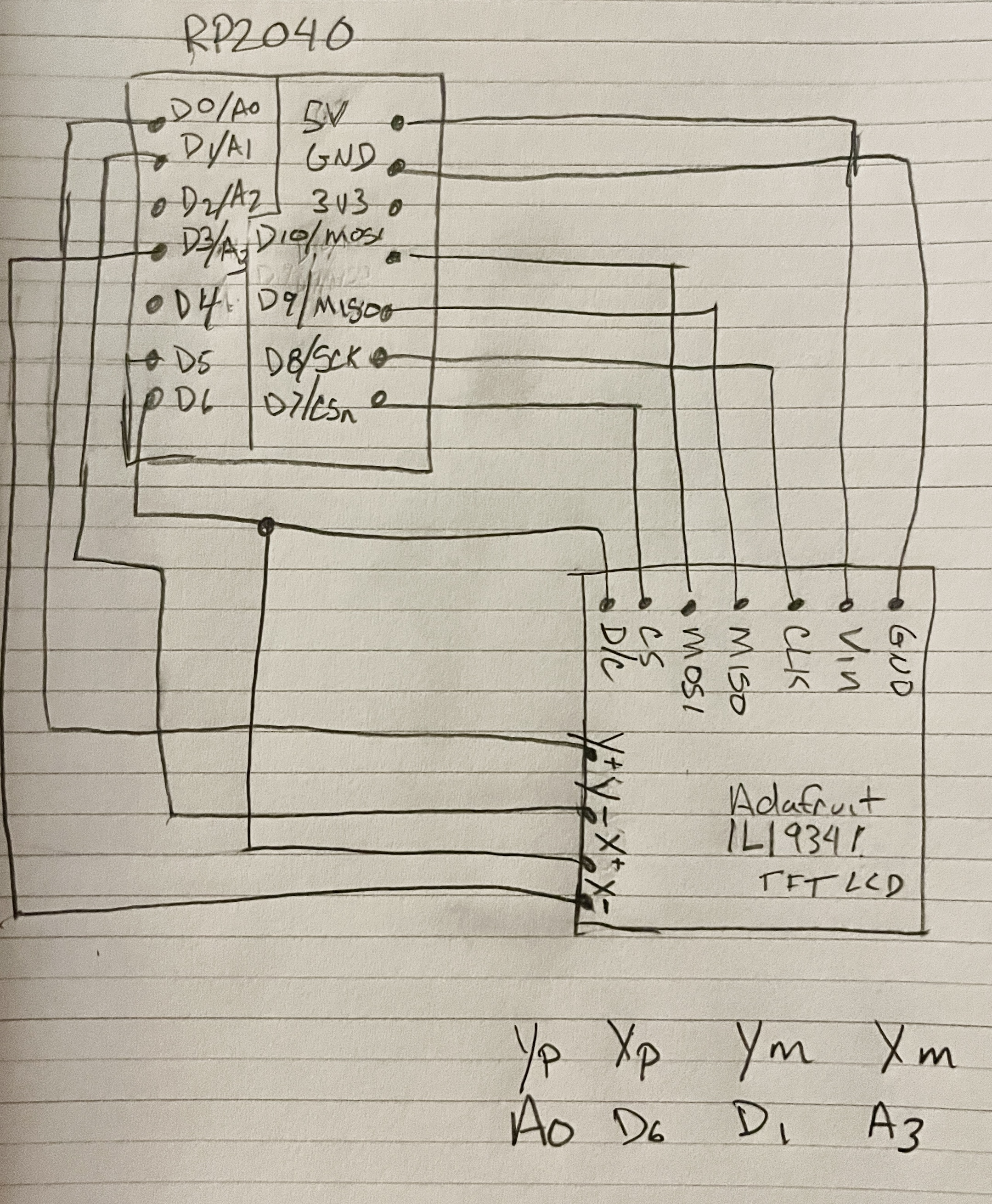
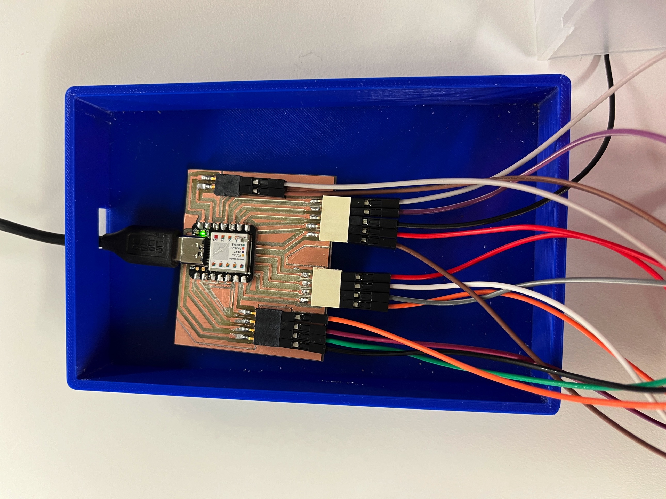
Wire Diagram
IT WORKS!
I ultimately changed from the Xiao RP2040 to the Xiao SAMD21 and was able to get the screen to work properly. I also had to uninstall and reinstall the Seeed boards from the Arduino board manager and then everything worked as intended.
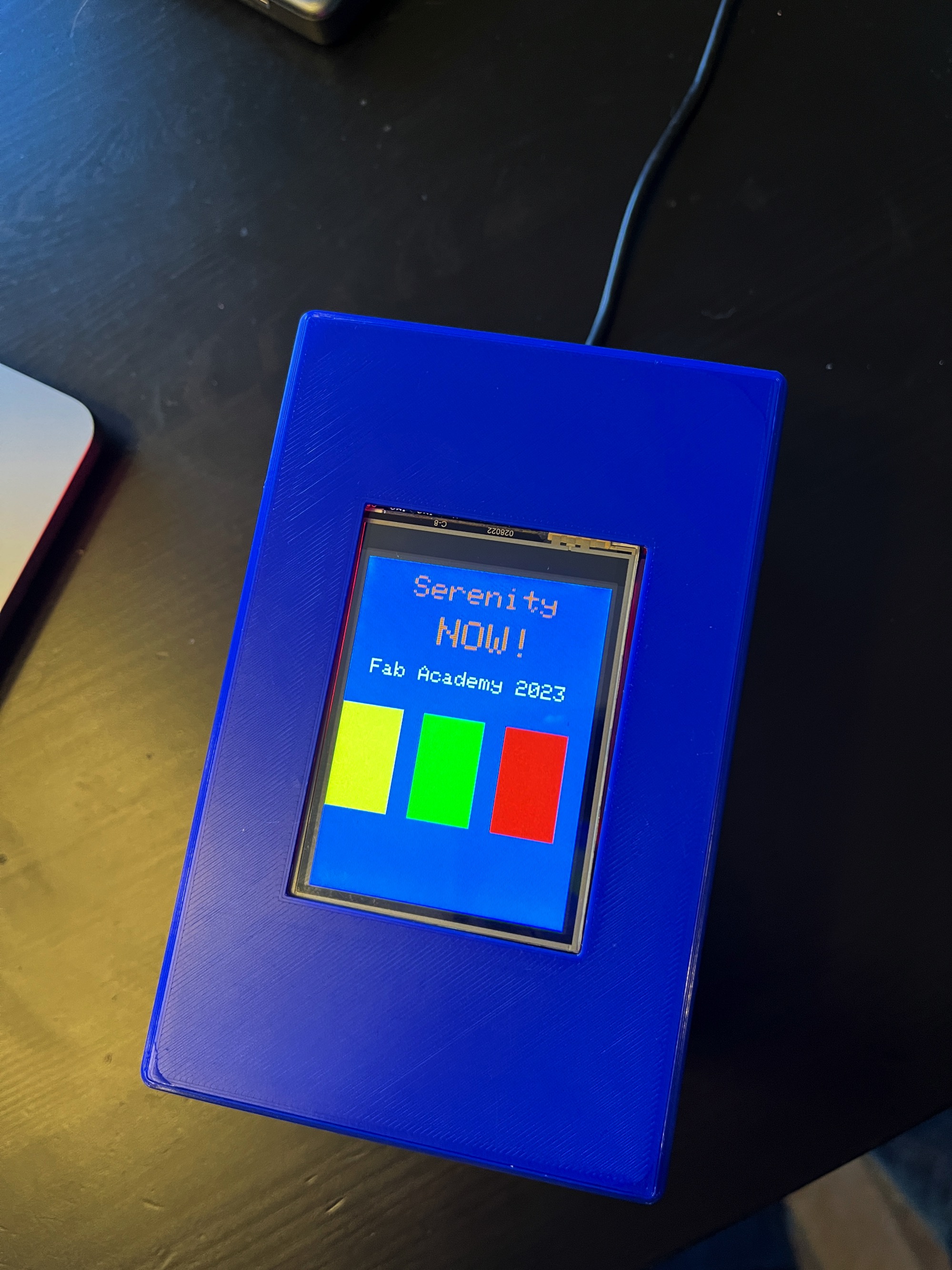
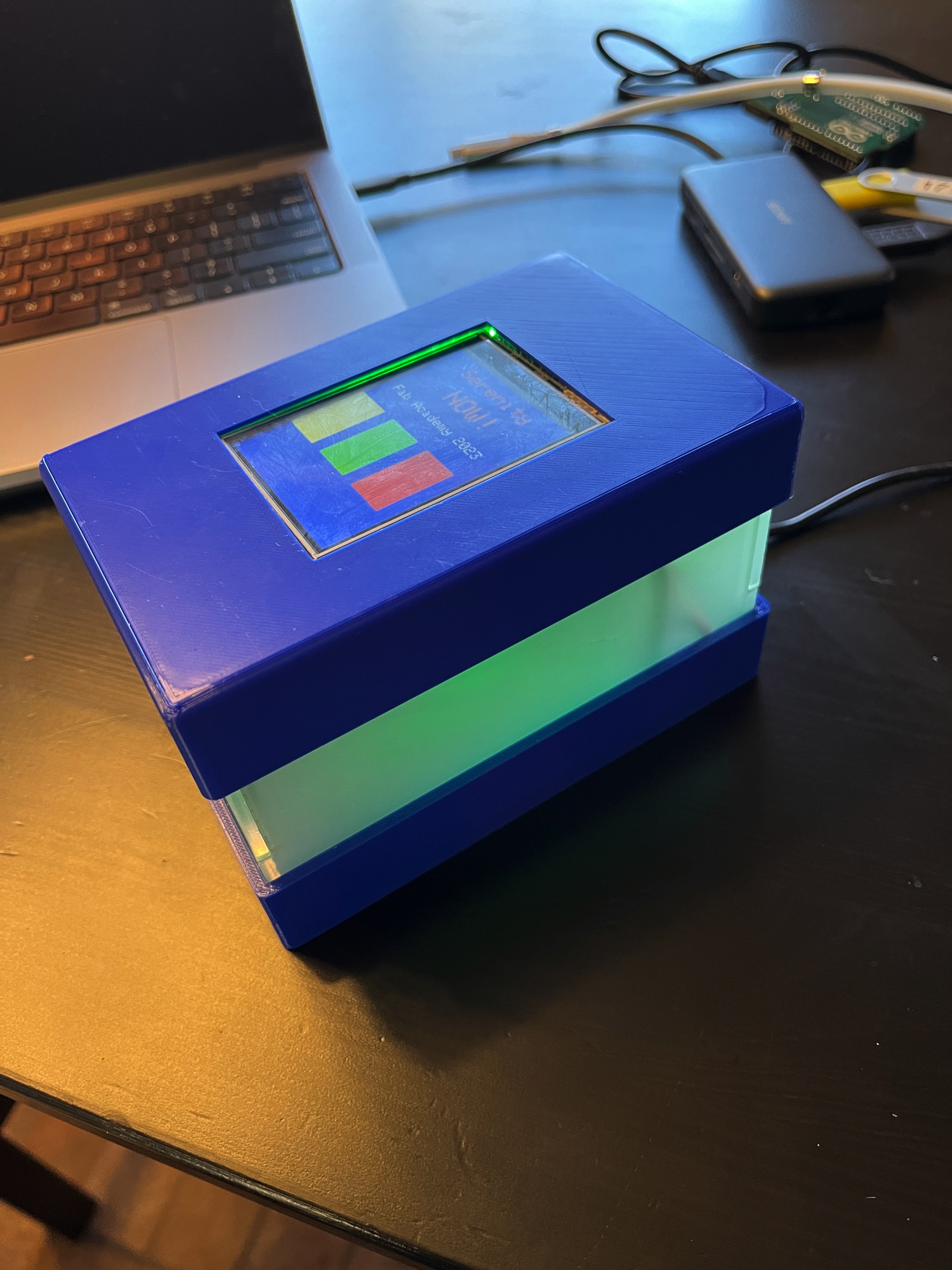
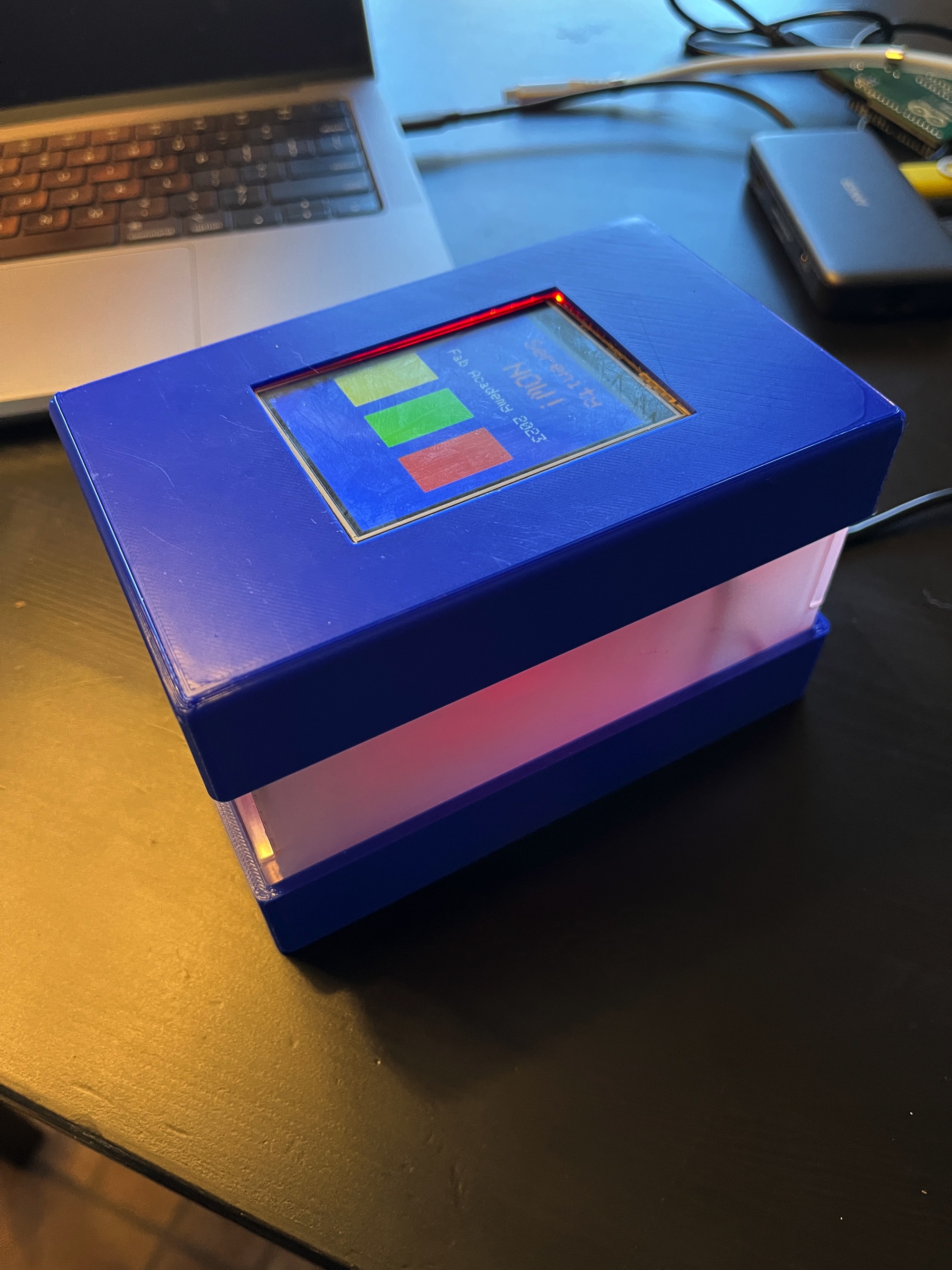
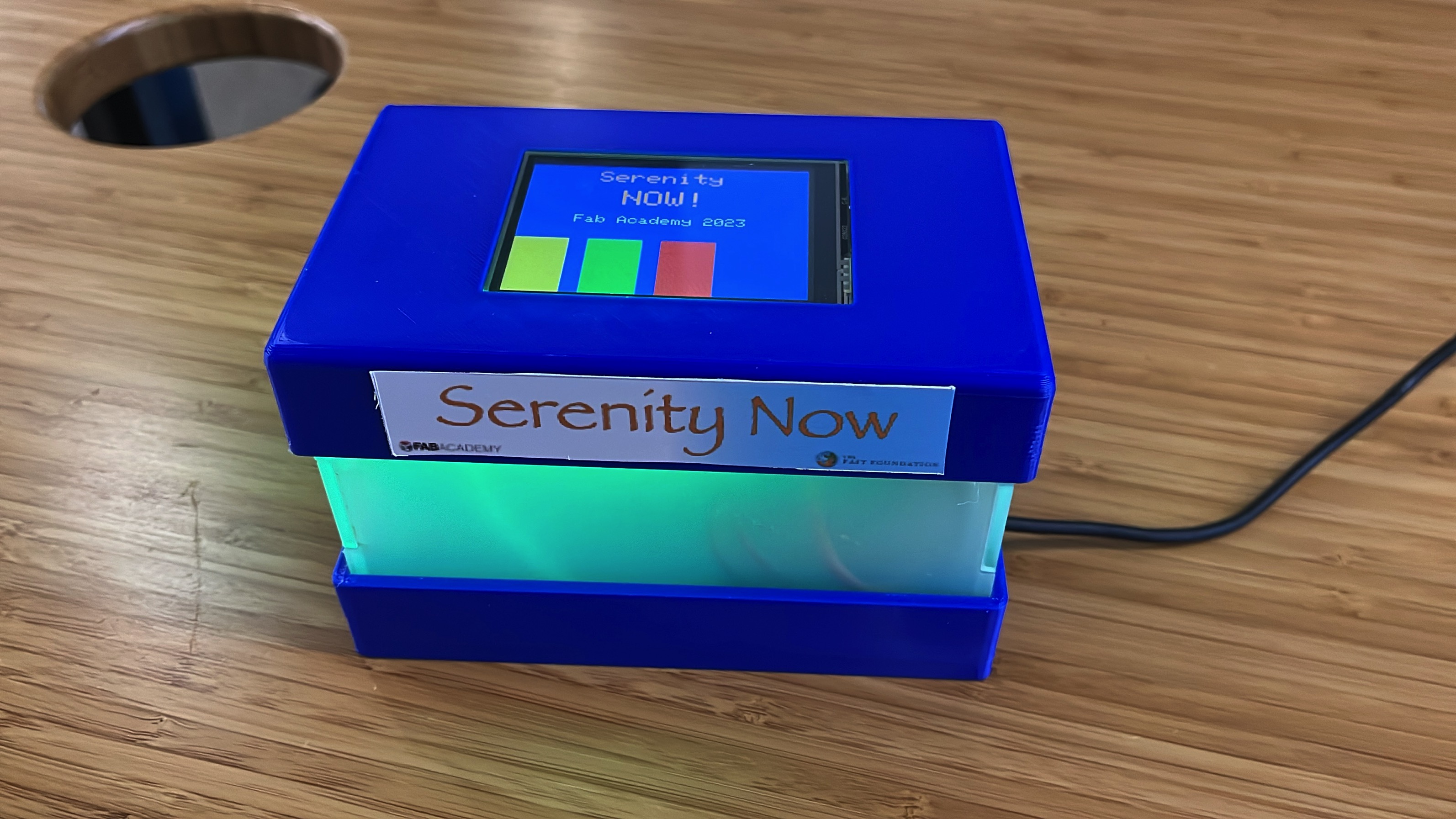
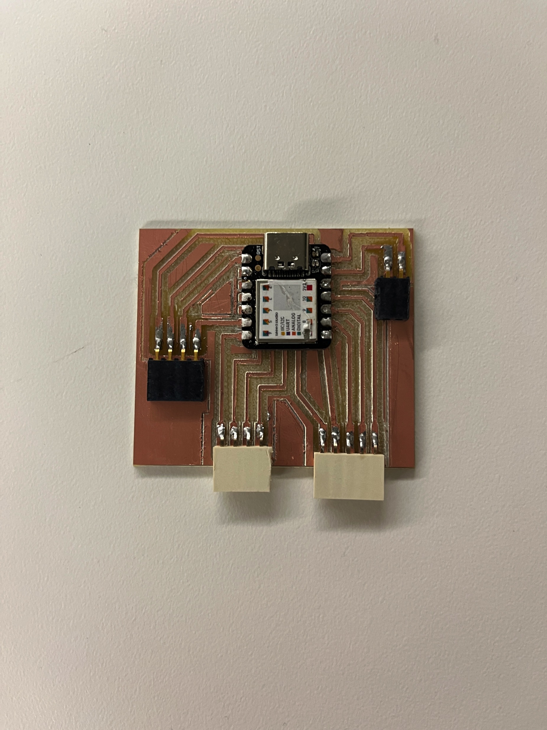
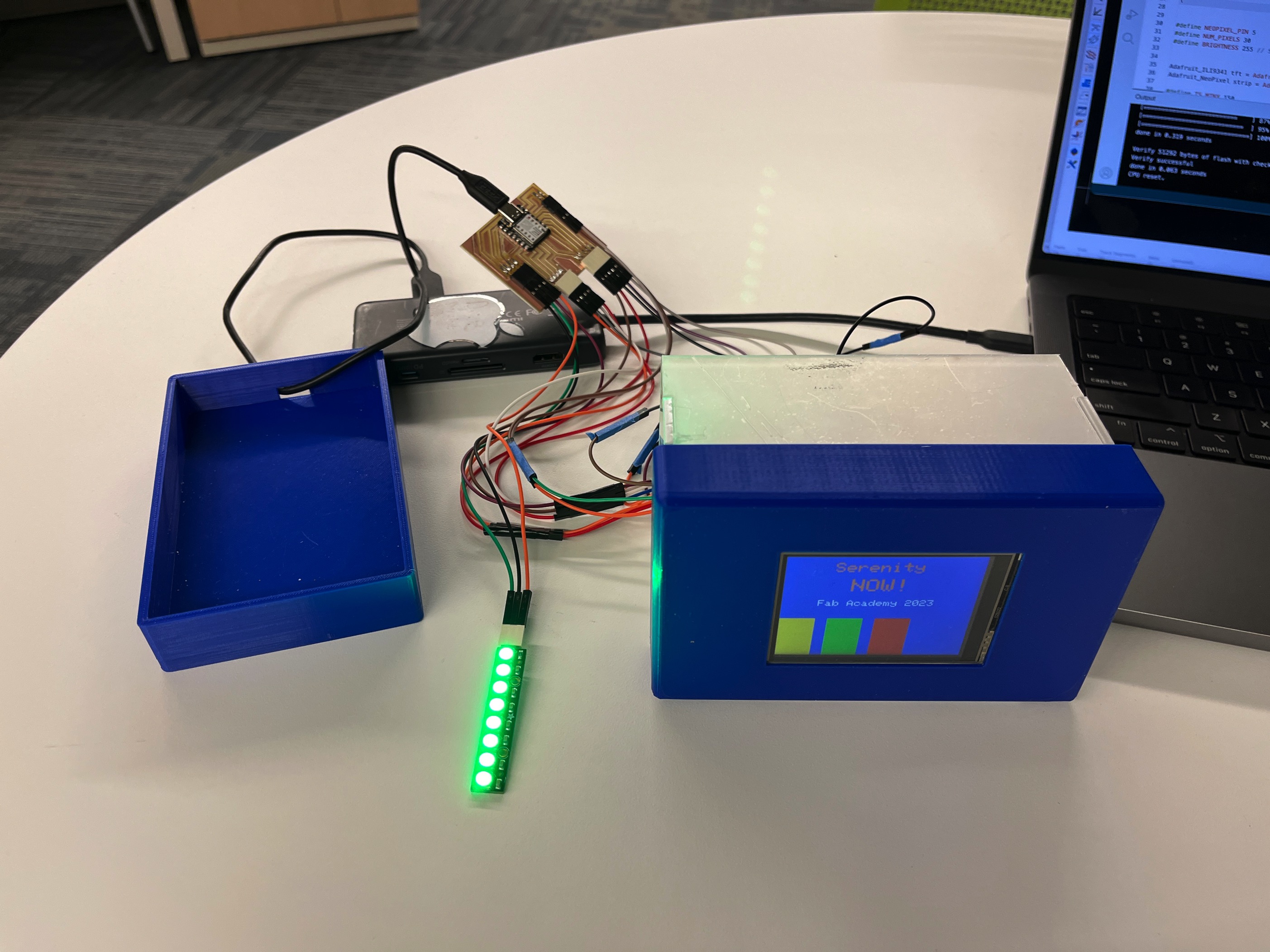
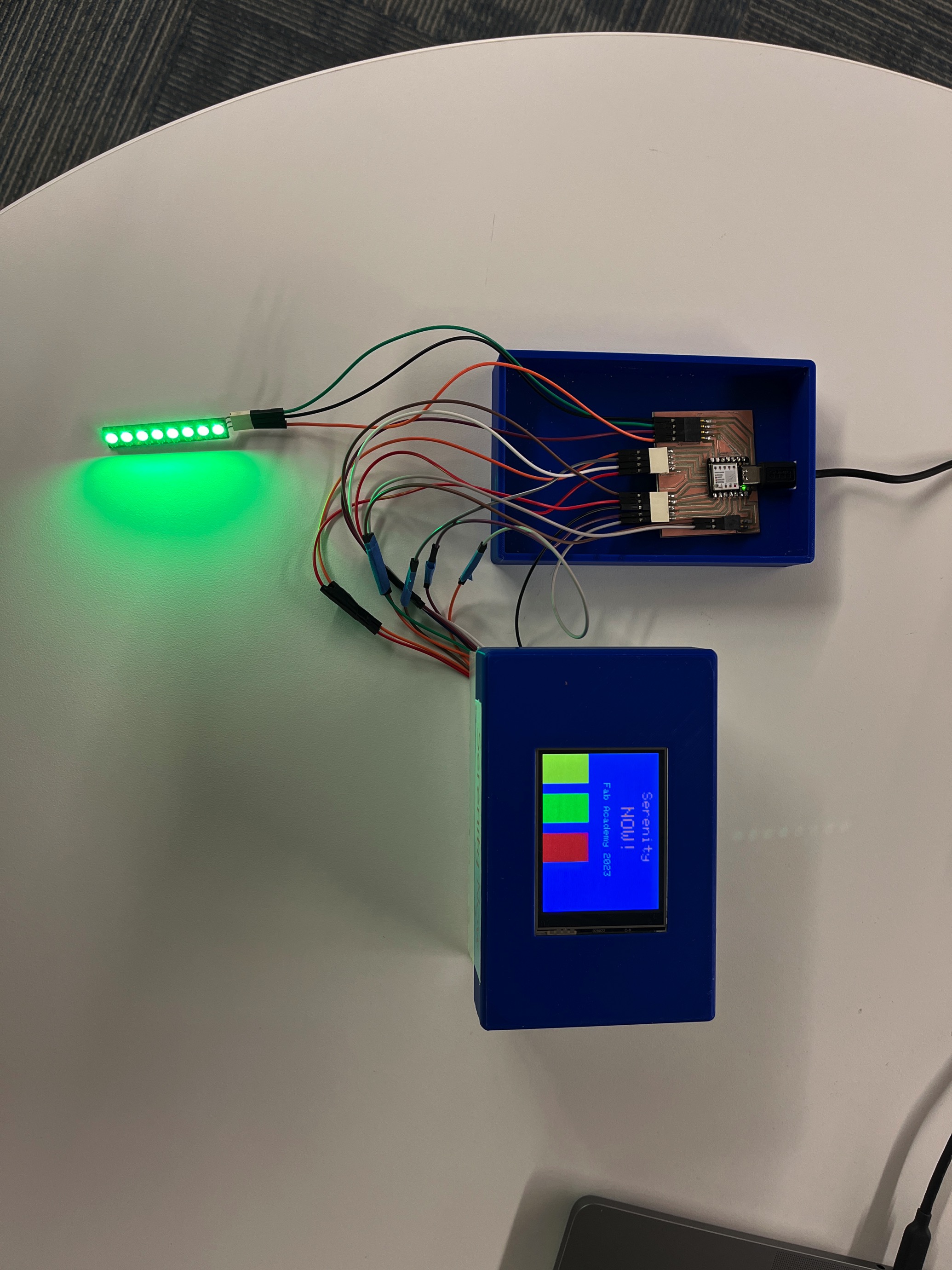
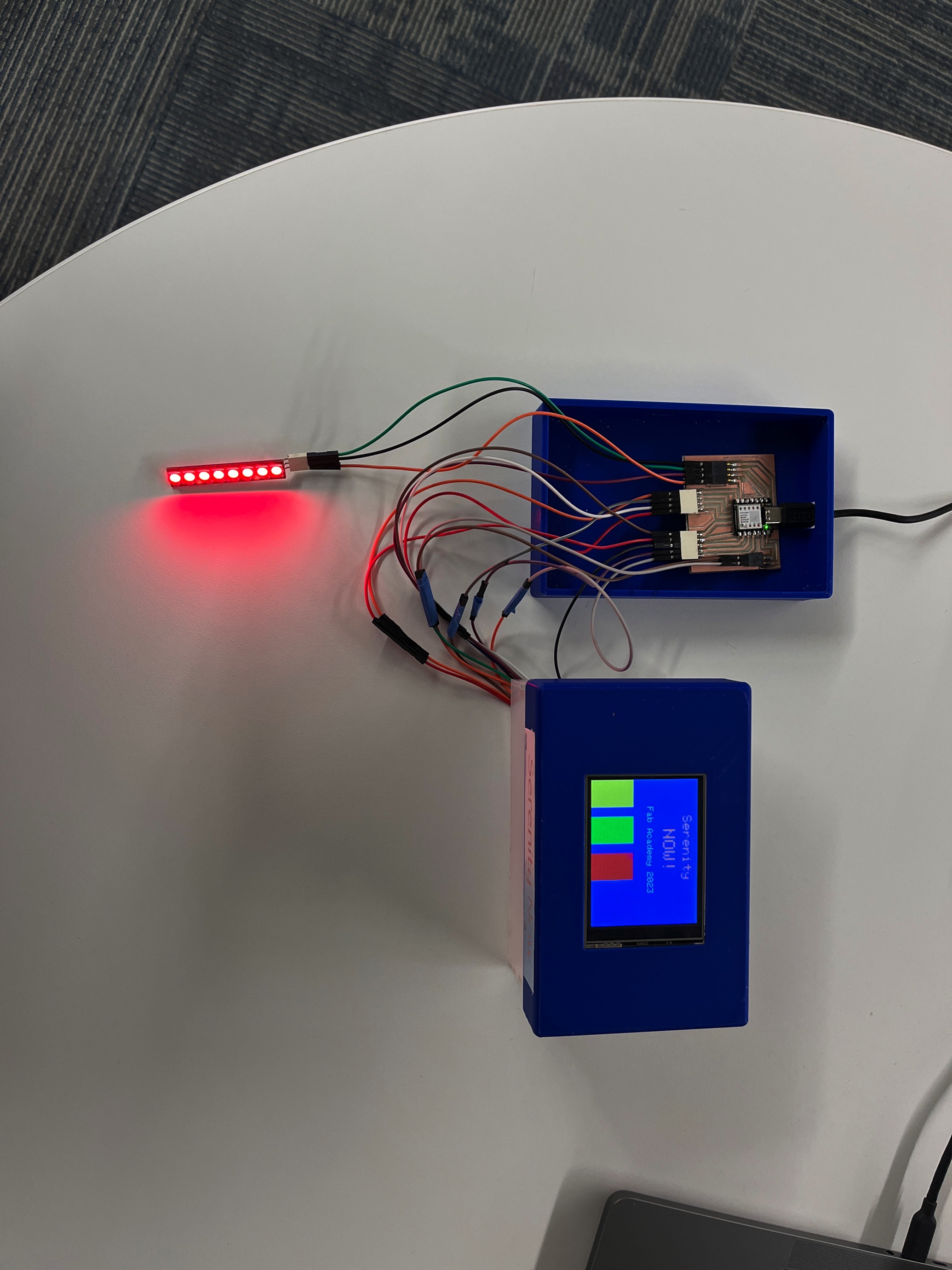
I found that the graphics would respond to a change in orientation (portrait vs landscape) but the touch positions did not so I am still working out the exact positions of the color buttons to align with the touch sensitive areas....but it all works its just a little off.
Final Code
  /*Seeeduino XIAO -> ILI9341
  Vin            -> Vcc
  GND            -> GND
  GPIO 3         -> CS
  GPIO 1         -> RESET
  GPIO 2         -> D/C
  GPIO 10(MOSI)  -> SDI(MOSI)
  GPIO 8(SCK)    -> SCK
  GPIO 0         -> LED
  */


  #include Adafruit_GFX.h
  #include Adafruit_ILI9341.h
  #include Adafruit_NeoPixel.h
  #include TouchScreen.h
  //#include XPT2046_Touchscreen.h

  #define Adafruit_ILI9341_DRIVER

  #define TFT_MOSI D10
  #define TFT_SCLK D8
  #define TFT_MISO D9
  #define TFT_CS D7
  #define TFT_DC D6
  #define TFT_RST D4

  //#define TFT_CS D3
  //#define TFT_DC D0
  //#define TFT_SCLK D10
  //#define TFT_MOSI D6
  //#define TFT_MISO D9


  #define NEOPIXEL_PIN 5
  #define NUM_PIXELS 30
  #define BRIGHTNESS 255 // Set BRIGHTNESS to about 1/5 (max = 255)


  Adafruit_ILI9341 tft = Adafruit_ILI9341(TFT_CS, TFT_DC);
  Adafruit_NeoPixel strip = Adafruit_NeoPixel(NUM_PIXELS, NEOPIXEL_PIN, NEO_GRBW + NEO_KHZ800);

  #define TS_MINX 150
  #define TS_MINY 120
  #define TS_MAXX 920
  #define TS_MAXY 940

  #define MINPRESSURE 10
  #define MAXPRESSURE 1000

  //Touchscreen X+ X- Y+ Y- pins
  #define YP A2  // must be an analog pin, use "An" notation!
  #define XM A0  // must be an analog pin, use "An" notation!
  #define YM D1   // can be a digital pin
  #define XP D3 // can be a digital pin


  TouchScreen ts = TouchScreen(XP, YP, XM, YM, 300);


  enum ButtonState {
    RED,
    GREEN,
    YELLOW
  };

  ButtonState currentButtonState = RED;

  void setup() {

    pinMode(TFT_DC, OUTPUT);
  pinMode(TFT_CS, OUTPUT);
  pinMode(TFT_SCLK, OUTPUT);
  pinMode(TFT_MOSI, OUTPUT);

    Serial.begin(9600);
    tft.begin();
    strip.begin();
    strip.show(); // Initialize all pixels to 'off'
    strip.setBrightness(BRIGHTNESS);

    // Clear the screen
    tft.fillScreen(ILI9341_BLUE);
     tft.setRotation(1);

  tft.setCursor(80, 12);
    tft.setTextColor(ILI9341_ORANGE);
    tft.setTextSize(3);
    tft.println("Serenity");
  tft.setCursor(110, 50);
    tft.setTextColor(ILI9341_ORANGE);
    tft.setTextSize(4);
    tft.println("NOW!");

    tft.setCursor(60, 100);
    tft.setTextColor(ILI9341_WHITE);
    tft.setTextSize(2);
    tft.println("Fab Academy 2023");

    // Draw buttons on the screen
    drawButtons();
  }

  void loop() {
    TSPoint touch = ts.getPoint();
   //tft.setRotation(2);


    if (touch.z >= MINPRESSURE && touch.z <= MAXPRESSURE) {
      // Touch event detected
      int16_t x = map(touch.x, TS_MINX, TS_MAXX, 0, tft.width());
      int16_t y = map(touch.y, TS_MINY, TS_MAXY, 0, tft.height());


      // Check if the touch is within the button areas
      if (x > 40 && x < 120 && y > 40 && y < 120) {
        // Button 1 is pressed
        setButtonState(RED);
      } else if (x > 40 && x < 120 && y > 40 && y < 240){
        // Button 2 is pressed
        setButtonState(GREEN);
      } else if (x > 280 && x < 360 && y > 40 && y < 120){
        // Button 3 is pressed
        setButtonState(YELLOW);
      }
      // Add more button checks as needed
    }
    {
    // a point object holds x y and z coordinates
    TSPoint p = ts.getPoint();

    // we have some minimum pressure we consider 'valid'
    // pressure of 0 means no pressing!
    if (p.z > ts.pressureThreshhold) {
       Serial.print("X = "); Serial.print(p.x);
       Serial.print("\tY = "); Serial.print(p.y);
       Serial.print("\tPressure = "); Serial.println(p.z);
    }

    delay(100);
  }
  }

  void setButtonState(ButtonState newState) {
    if (newState != currentButtonState) {
      // Change the Neopixel color based on the button state
      switch (newState) {
        case RED:
          setColor(0, 255, 0); // Red
          break;
        case GREEN:
          setColor(255, 0, 0); // Green
          break;
        case YELLOW:
          setColor(255, 255, 0); // Yellow
          break;
      }
      currentButtonState = newState;
    }
  }

  void setColor(uint8_t red, uint8_t green, uint8_t blue) {
    for (int i = 0; i < NUM_PIXELS; i++) {
      strip.setPixelColor(i, strip.Color(red, green, blue));
    }
    strip.show();
  }

  void drawButtons() {
    // Draw button 1
    tft.fillRect(0, 145, 60, 100, ILI9341_YELLOW);
    tft.setTextColor(ILI9341_WHITE);
    tft.setTextSize(2);
    tft.setCursor(55, 70);
     //tft.print("RED");

    // Draw button 2
    tft.fillRect(80, 145, 60, 100, ILI9341_GREEN);
    tft.setCursor(175, 70);
    //tft.print("GREEN");

    // Draw button 3
    tft.fillRect(160, 145, 60, 100, ILI9341_RED);
    tft.setCursor(295, 70);
    //tft.print("YELLOW");


  }
Final Design Files
Final KiCad File Final Code File Serenity Now Base .stl file Serenity Now top .stl file Serenity Now side .stl file Serenity Now Base .stl fileVideo Final Slide