Mechanical Design and Machine Design
This week we are tasked with making our own machine to do something. This was to be completed as a group assignment with no individual assignment other than documentation on our own websites. Below you will find my research, documentation of design and build, and a test run of the machine.
Group Assignment Specifications
Link to our Group Page Our tasks are as follows:
- Design a machine that includes mechanism + actuation + automation + application
- Build the mechanical parts and operate it manually
- Document the group project and your individual contribution
Research in Machine Design
This week was a bit overwhelming when it was originally assigned to us; I have no idea how most machines work and have no idea how to build one! So I needed to do some research on machine processes and simple mechanical machines. I did previously know about 3D printers and the additive process involved in using them, so I knew I would feel most confident in designing and building a machine that works in a similar way.
Brainstorming with Group
Andy, Nikki, and I had a meeting to brainstorm what kinds of machines we would be interested in building and what would be managable for us and our increasingly busy schedules. We generated a small list before deciding on the final machine.
- Large format 3D printer
- Small range robot
- Tabletop CNC Milling machine
- CNC Pen Plotter
- All3DP-Pen Plotters: The Best XY Plotters in 2023
- Medium-An intro to Pen Plotters
- Instructables-Mini CNC Plotter - Arduino Based
Parts and Pieces
We decided to have a tiny bit of a head start by using some parts from an old 3D printer that doesn't work anymore. We began by deconstructing and taking an inventory of parts that we could use for our new machine design. All three of us worked together to take the old 3D printer apart.
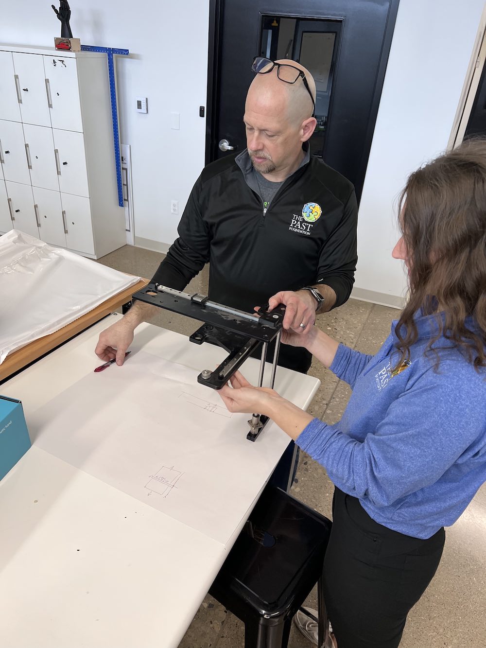
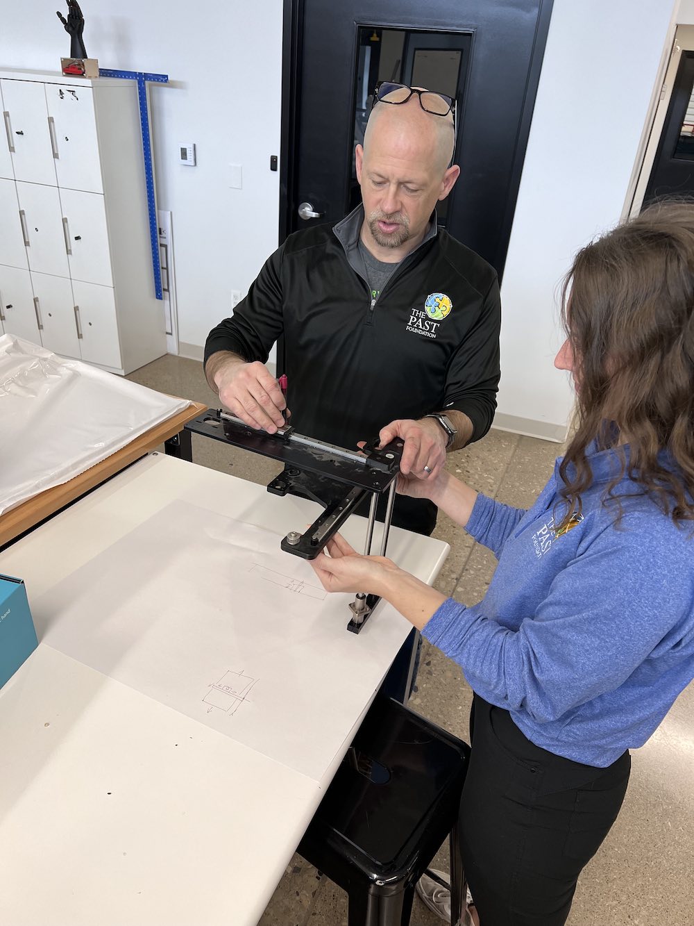
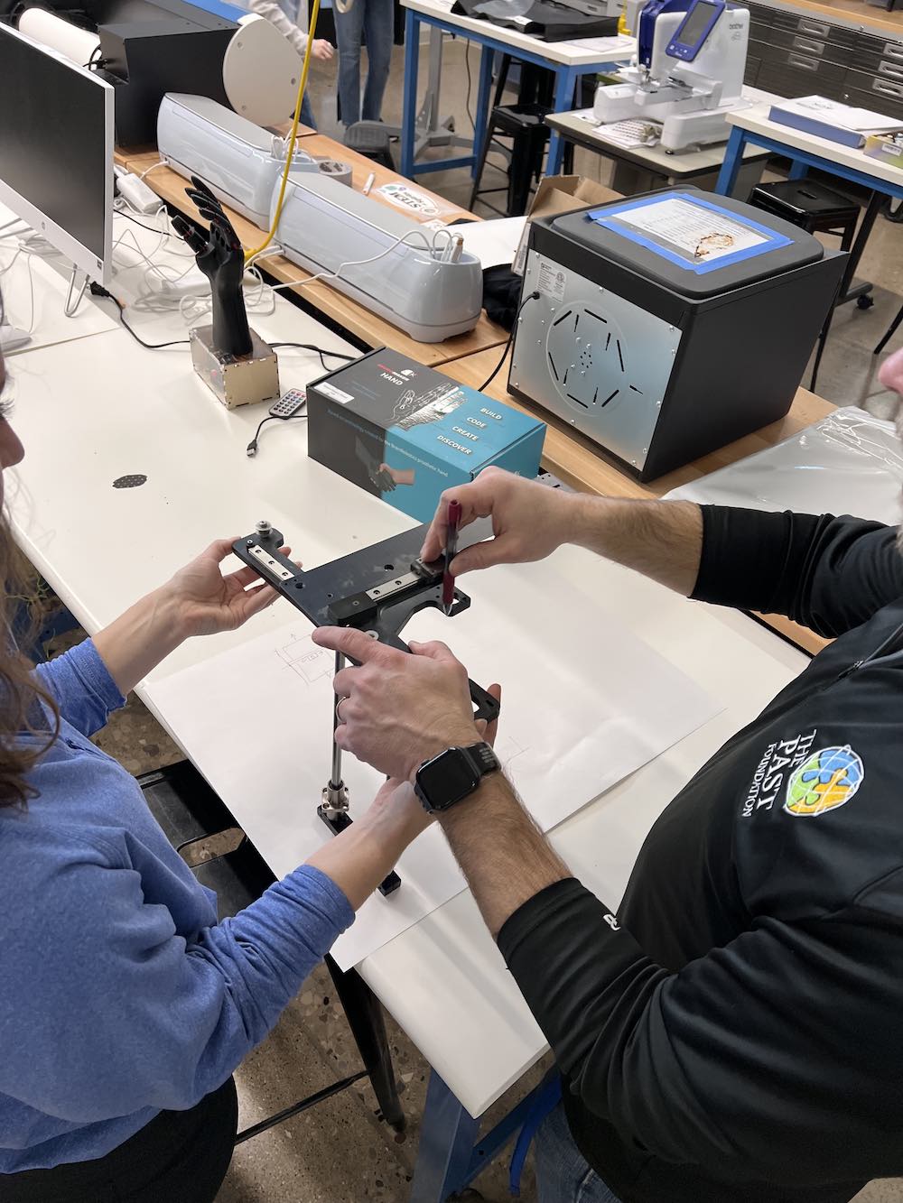
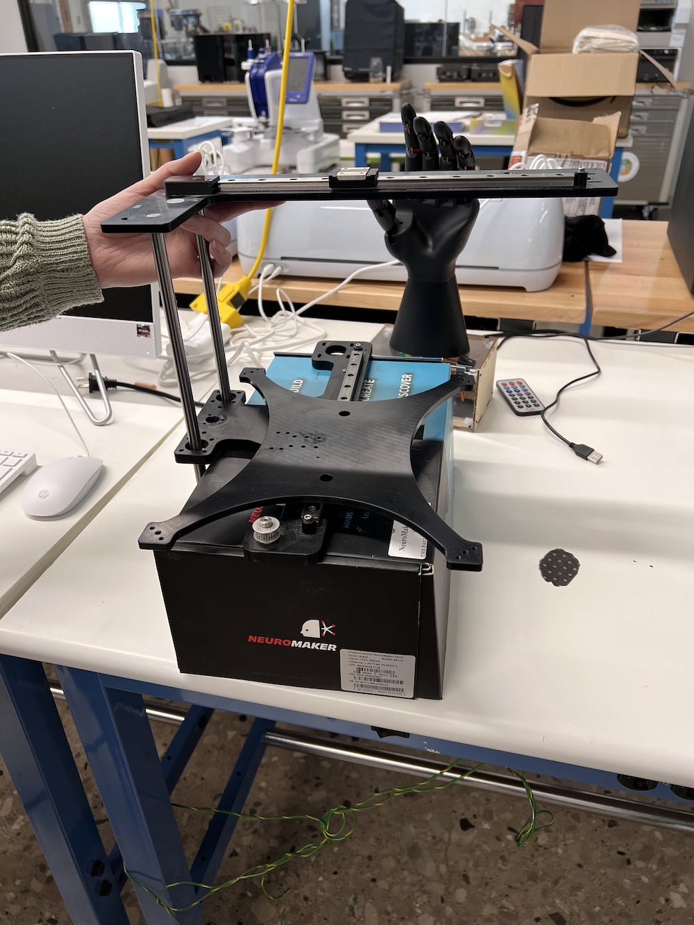
After taking apart our old machine to make a new one, we were left with a few pieces that we wanted to keep to use in our new design.
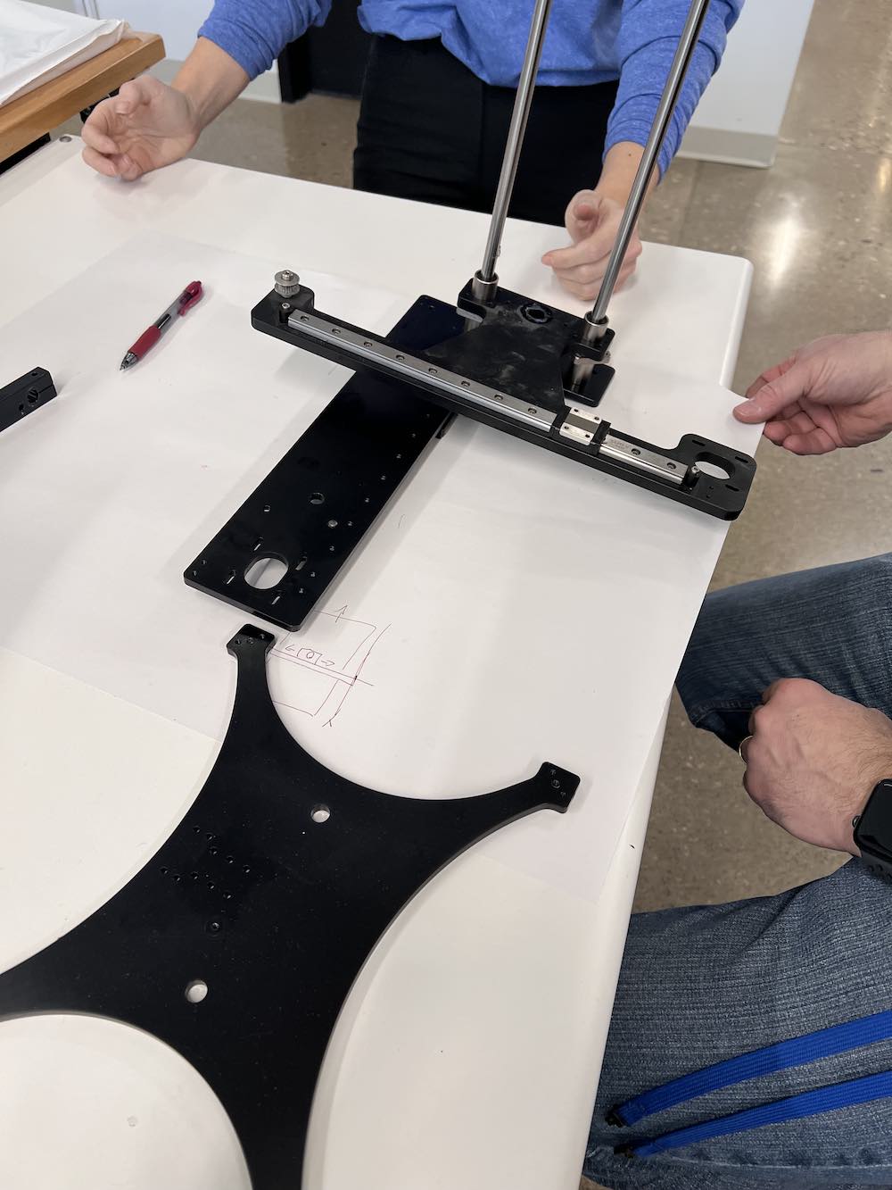
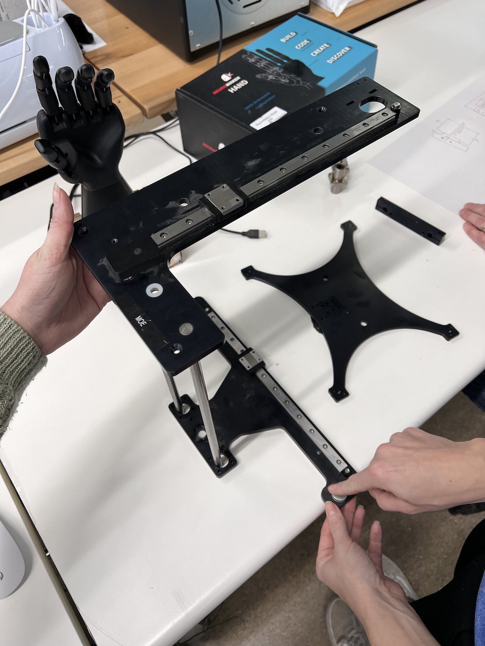
These are images of my group and I trying out different configurations that we could use to set up our pen plotter. Also in these images, are some of the pieces we plan to reuse in our machine.
The following materials are being reused from the previous 3D printer:
- Rails & Carriages - the two silver metal rails are being reused on our own wooden arms we are laser cutting.
- Silver poles - the two supporting posts were removed and are being used to support the weight of our structure.
- Stepper Motors - the X, Y and Z motors are being removed, and reused in the new machine.
- Z-Rod - the Z rod that will control the Z movement of our machine is being reused.
- Belts - the belts that connect the motor with the carriage will be reused to ensure we have a proper fit and function.
- Build Plate - we are using the build plate in our design, but we will be adding to it to make the build area larger.
Pen Plotter - Brainstorming the Design
The design started with inspiration from the movements of 3D printers. We knew we wanted to maximize our plotting area, however, with the pieces we are reusing, the orientation of the pieces is partially hindering the range of motion our machine has. (Forewarning: this is the first design, there is a second, and final, design later in this page.)
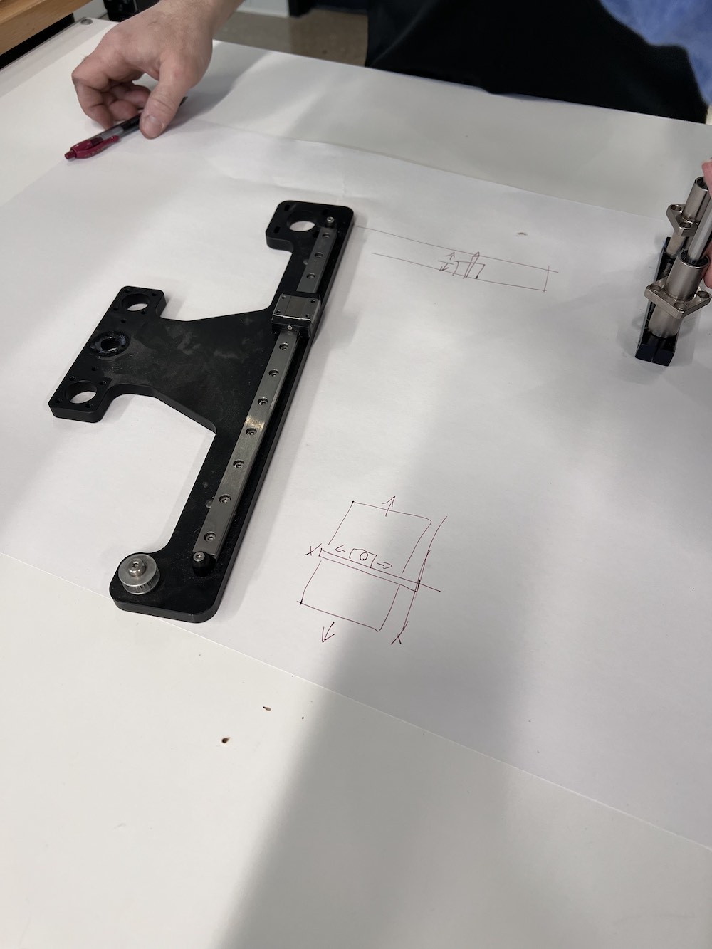
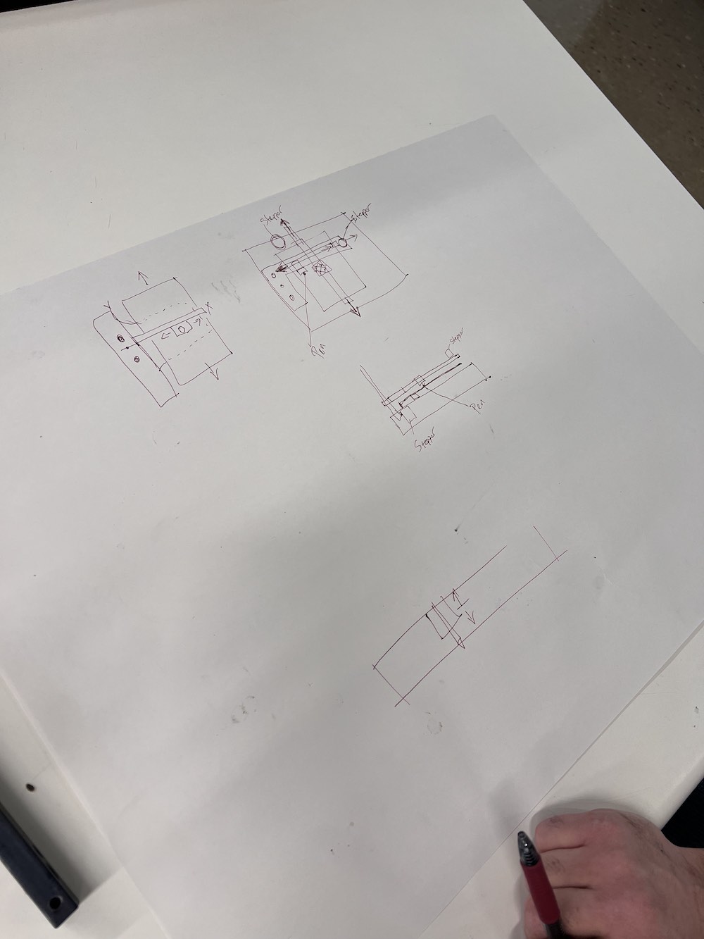
The images above document our brainstorming and part of our designing process. The last image is a rough idea of how the machine will be set up. We plan to laser cut 1/4" thick wood to form the X and Y axes that hold our rails, motors, and belts. We also plan to laser cut and assemble a finger-joint box to house our electronics, as well as a stock of paper that can be used with the plotter. The box will also raise our build plate up so we will not have to trim our metal support rods as much.
3D Modeling
To make a model of our machine, we decided to use Onshape. All 3 of our group members have used Onshape before and figured this would be the easiest way to share a document and work on it together.
I started by taking dimensions of each component, and tracing the size onto a large sheet of paper. In Onshape, you are able to upload an image as a background, which you can then use to create a shape in Onshape. This was a bit tedious, but we were able to model it pretty accurately. You can find our original design file for Onshape at the end of this page. You can follow along our modeling process through the images below.
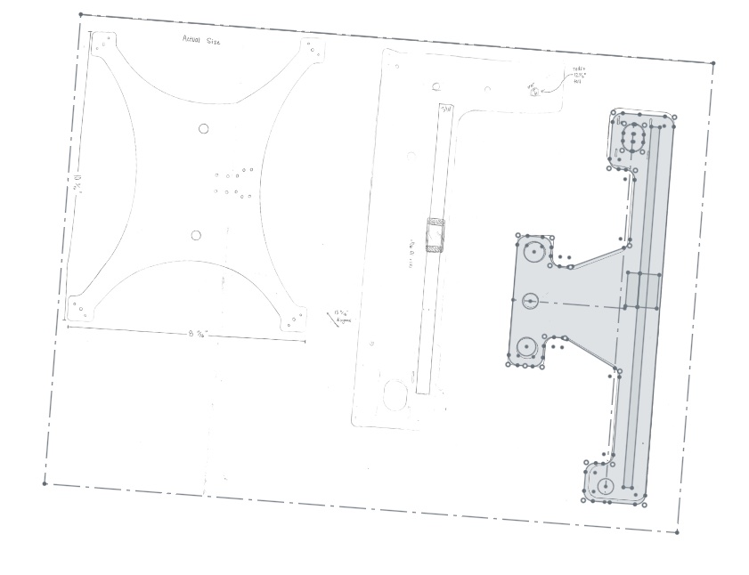
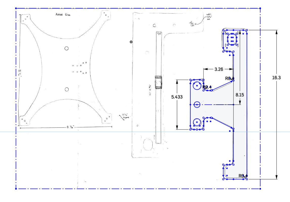
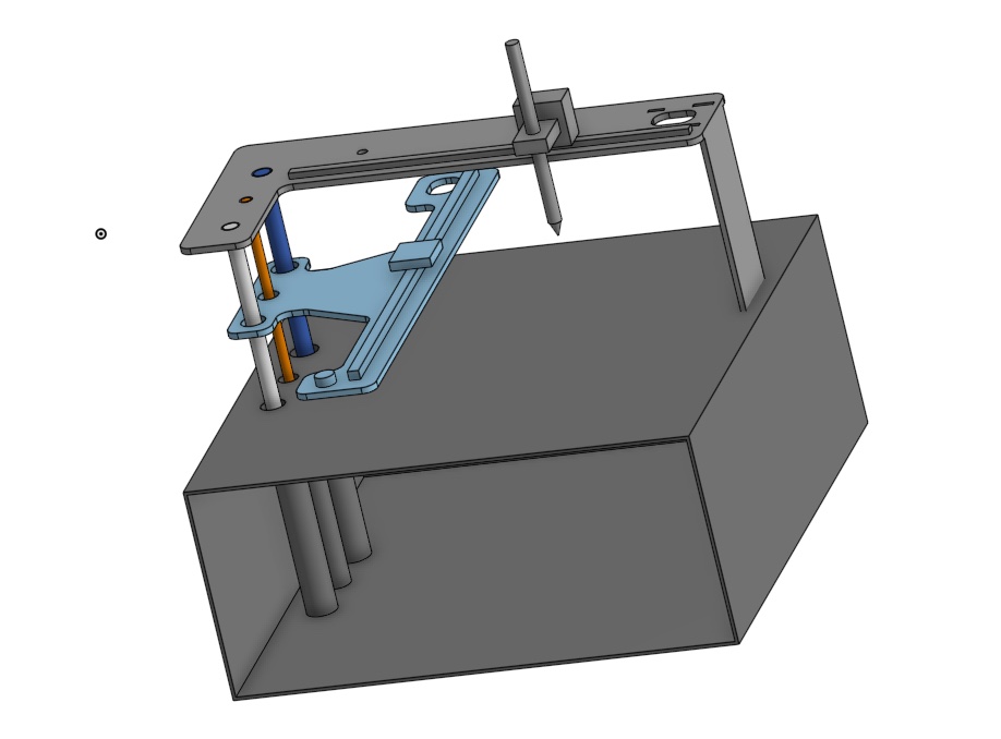
The last photo is the final model we designed for Attempt #1. My process was fairly simple in Onshape. I used the actual sized sketch photo to make each part an accurate size, then extruded the sketch to match the thickness of our wood, 1/4" plywood. I also modeled where we would have the supporting poles, Z Rod, and the rails and carriages. I ended up doing all of the modeling of the machine in Onshape, which I was happy to do, since it is something I already had a familiarity with.
Building the Frame
To cut out the pieces of our machine, we created a drawing of the parts in Onshape using the model we just designed. In the model, we did not create a finger-joint box. We decided to use our previous design from week 3. Nikki shared her box design document with me, and we worked to add tabs in the proper locations and to resize it to fit our electronics and our paper storage.
We used Onshape again to design a 3D model of the box and made a drawing of each of the 3 pieces we needed. We needed 1 drawing for the top and bottom of the box, 1 for the sides and section divider, and 1 design for the back of the box. We used parametric design so it was easy to adjust the size of our box as we went through our design process. Once we had our pieces designed and properly scaled, we exported the drawings as SVG's and we headed back to our shop. Here, we used Affinity Designer to import our SVG drawing, then arranged our pieces for laser cutting.
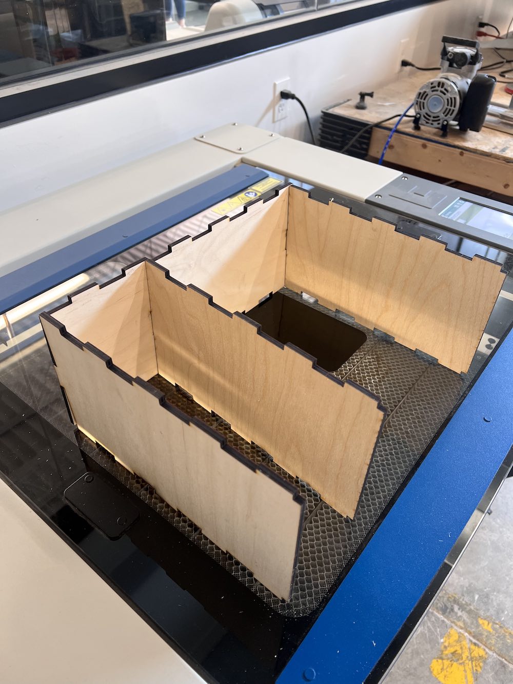
This was halfway through our box assembly, it was here that I realized our joint fingers were not lining up properly, so we needed to re-design and cut the tops and bottom pieces. I quickly switched the tabs to be opposite on the piece I needed for the top and bottom, then sent that to the laser cutter to be cut.
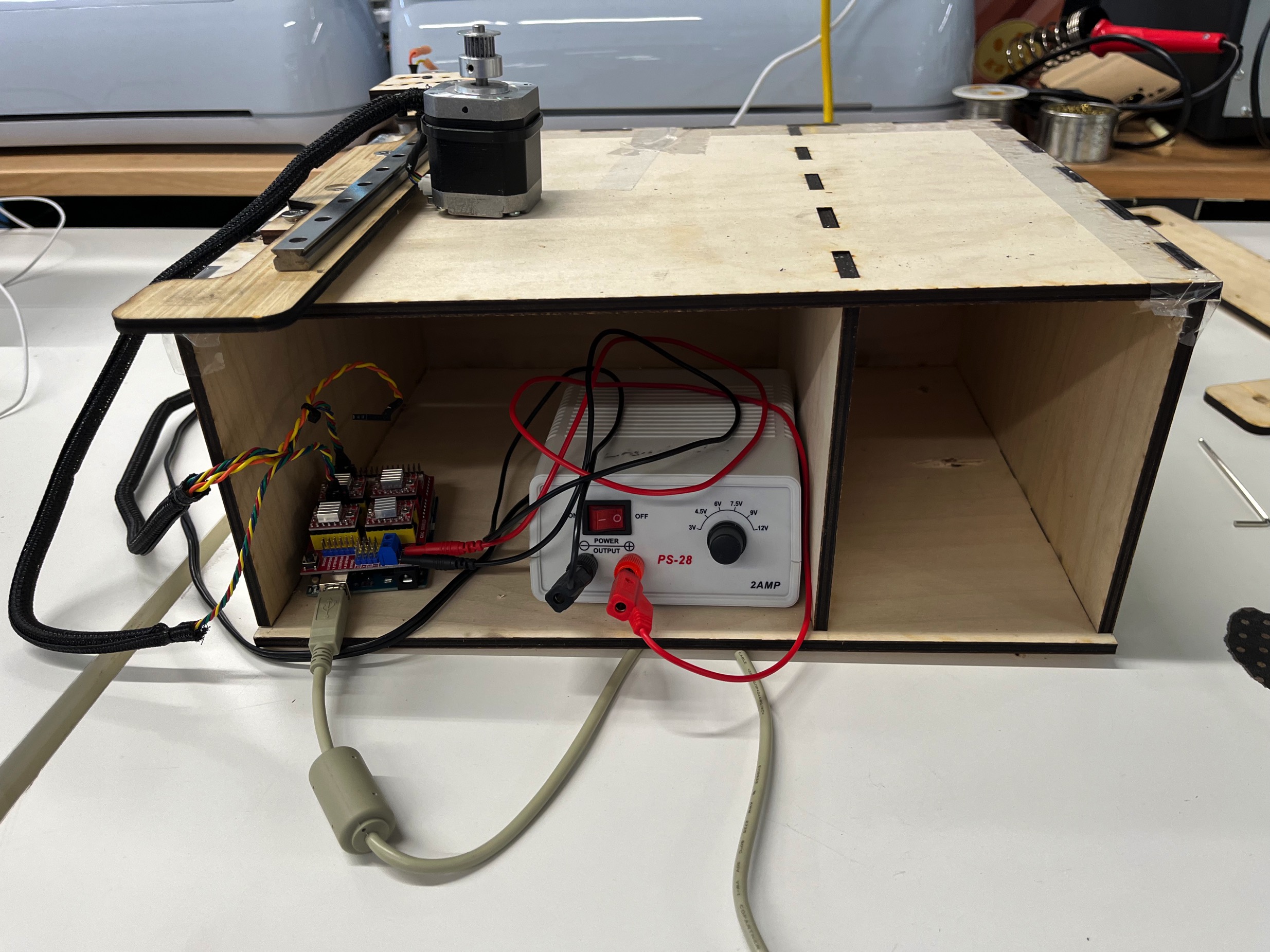
This is the box component put together, with the electronics components in the bottom compartment, thanks to Andy.
Electronics
Andy took the lead on figuring out how to reprogram an old Raspberry Pi. We knew we wanted to send G-code to our machine, as this will generate a toolpath for the machine to take when executing our inputs.
We ran into a lot of issues when trying to make the electronics communicate with our motors. Because we were using the motor shield and Raspberry Pi from the old 3D printer (that did NOT work) we are unsure if the problem we are running into lies there, or elsewhere in the code or in the transfer between the computer and the Raspberry Pi. We are actively trying other solutions and trying to find a G-code sender that will work. We are also looking into getting another motor shield and trying it.
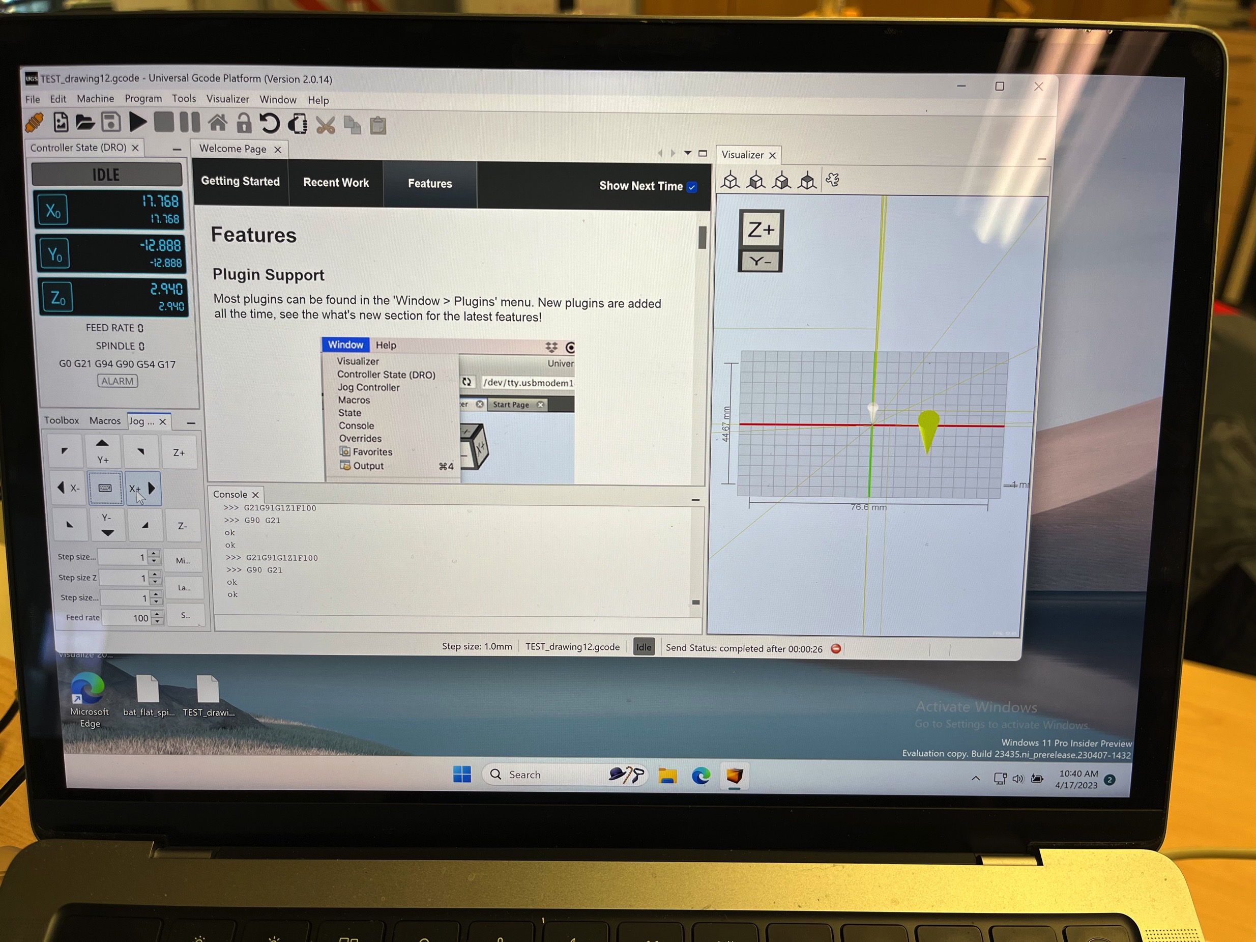
He used Universal G Code Sender (UGS) to code the plotter. We finally figured out that we should be using Parallels to run Windows on our Macs and this helped sending the program to the board of our plotter. After much trial and error, Andy got the electronics working and with the physical components from Nikki and myself, we had a working plotter (in attempt 2).
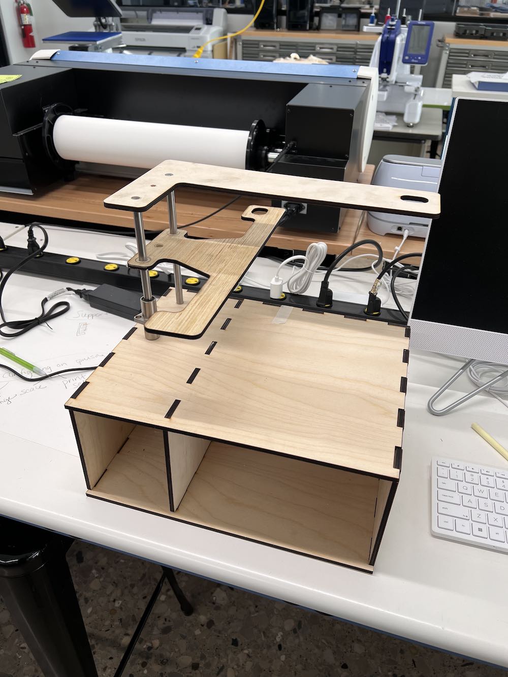
Putting it all together Attempt 1
It was at this point that we realized we may have overcomplicated the design, and could take a different approach to make an even better, more aesthetically pleasing pen plotter.
Attempt 2
Changing the Design Slightly
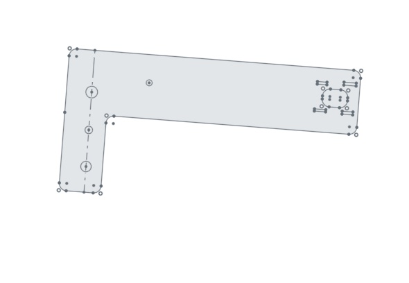
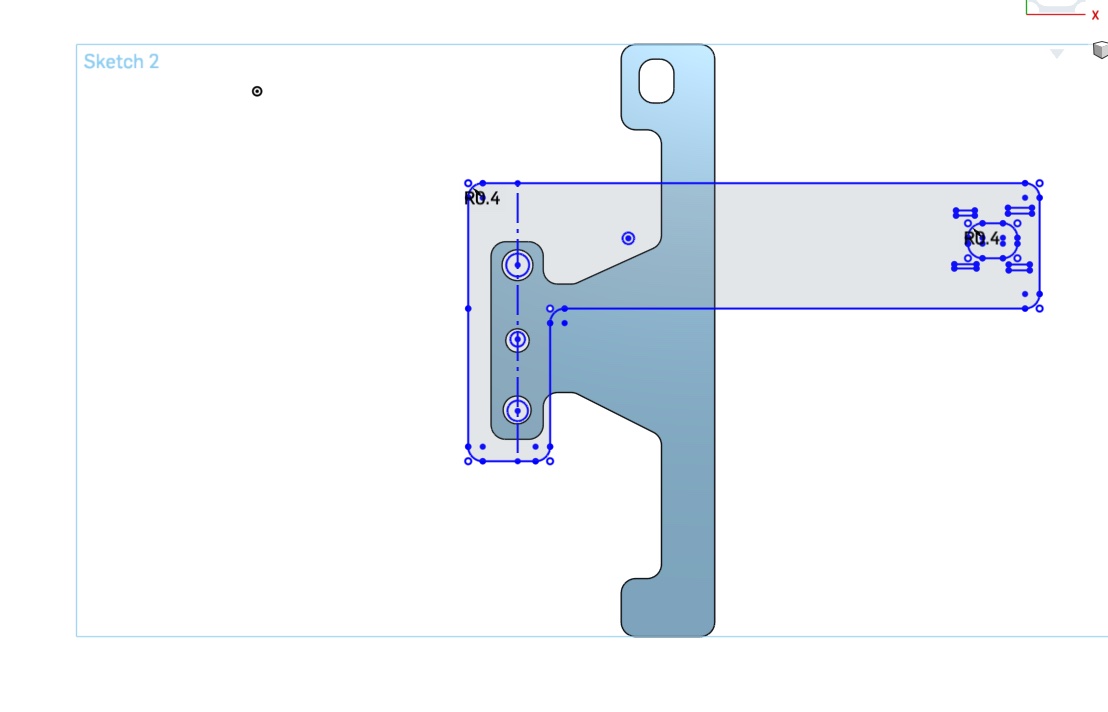
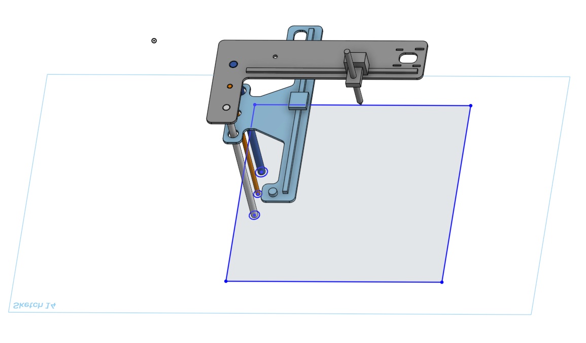
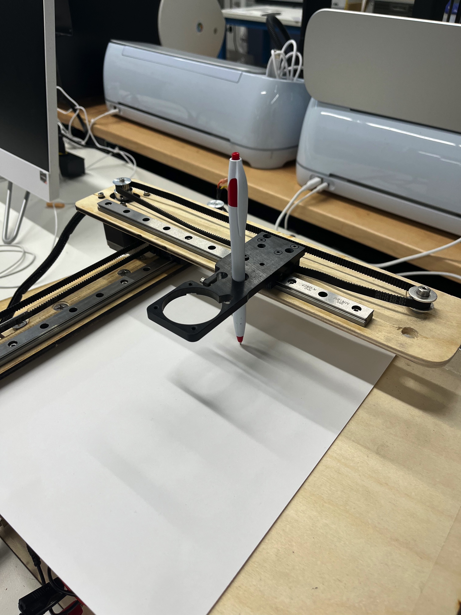
After the first attempt at making this machine, and it not quite working out, we decided we had a better design to move forward with. In this new design, the Y-axis that has the pen attachment would connect to the X-axis rail carriage. The Y-axis would be mobile ontop and allow for a greater area for the pen plotter to move. The Y-axis is the same file as the X-axis in this second design. Our build space would work for about the size of a regular piece of paper (8.5"x11").
The design utilizes the same storage box, X-axis pieces, belts, rails, carriages, etc. The only difference is removing the vertical support poles and the Z-Axis Rod. To move the pen up and down on the paper, we attach a swervo motor to move it about a centimeter so the user would have enough room to place the paper and not worry about drawing any additional marks.
Files
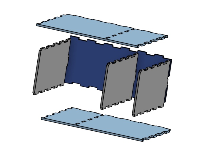
Screw Pad File X & Y Axis Part File Box Base FileThe box base file was previously utilized in week 3 by Nikki, she designed this box originally as a utensil holder, but we saw an opportunity to reiterate it for this machine design. There were slight modifications post-exporting and pre-laser cutting that occured. The second divider on the inside was removed and the holes were filled in. The size was scaled very slightly to accomodate the size and weight of our mechanical and electronics components. The image below is a deconstructed model of what the modified box looks like.
Future Opportunities
If we were to reiterate this design and make it better, one thing we would need to change is the tension in the belts themselves. We had decent tension, but for the most fluid pen strokes, both belts need to be under high tension. This will reduce the shake.
Another thing I would change is the electronics. With what I know now about electronics and machines, I think we could have designed a board that would be better suited for this project. This would also give us essentially a blank slate to start with.
I would also like to make the pen holder component a little different so we can change the pen type to a marker, sharpie, dry erase, etc. This would give more versatility.
Lastly, it would be super cool to create a machine like this, but without the base. Basically the X and Y axis' could rest on stilts above any flat surface and be able to work. Another cool idea would be to make it controllable via a joystick, phone, tablet, or maybe a touch screen remotely.