Week 13

Networking and Communications

By Patricia Samudio Salinas — on

Networking and Communications

Week 13 (less weeks to go 😱). This week we learned about different ways to communicate between devices:

  1. Wired communication (Parallel): Asynchronous, SPI, I2C
  2. Wireless communication (Serial): Bluetooth, WiFi.

In addition, I explored documentations and found a blog, which explains about Network Topology. In the article, it says that a network consists of several components, such as different devices called nodes and links or connections. These connections can be arranged logically or physically. There are two types of connections in a computer network system. These types are as follows:

  1. Physical Network Topology: It can be explained as the type of connection that is tangible. These are the physical connections in a network such as wires, routers, switches, cables, etc. It is the physical layout of nodes and the connection between the nodes of the network.
  2. Logical Network Topology: It can be explained as the non-tangible part of the connection or the software configuration of the network. It shows how data flows inside of a network. An example of such configuration is VLAN’s (Virtual LAN’s). Logical topologies of two systems can be the same even if they have different physical topology.

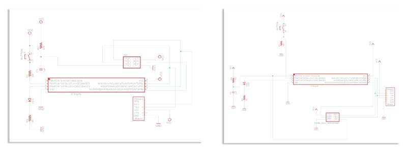
Among the tasks to be performed is to establish a communication between two projects:

  • Alejandro: servo motor (output) or temperature sensor (input)
  • Glenda: speaker (output)
  • Paty (me): capacitive sensor (input) or LCD display (ouput)

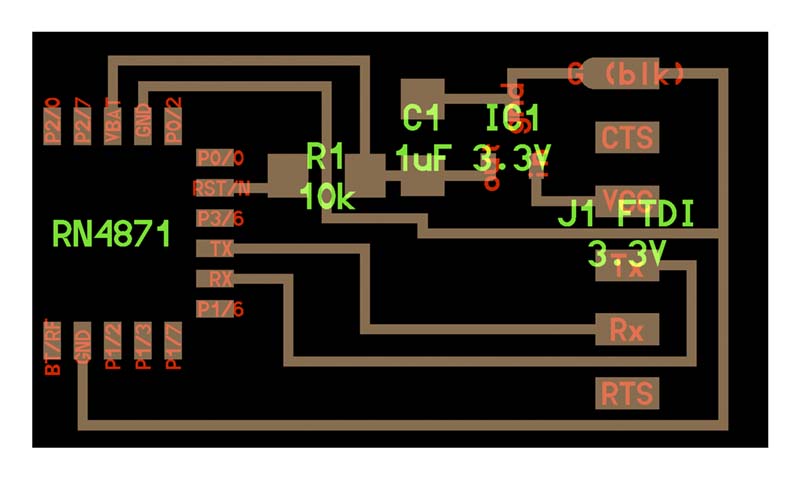
Well, but we chose the way of communication via Wireless, through the RN4871 (2.4 GHz Bluetooth) module (🫣) since some of the final projects would need this module and therefore it was a good opportunity to test.

This low power module, whose characteristics can be found in the following Data Sheet.

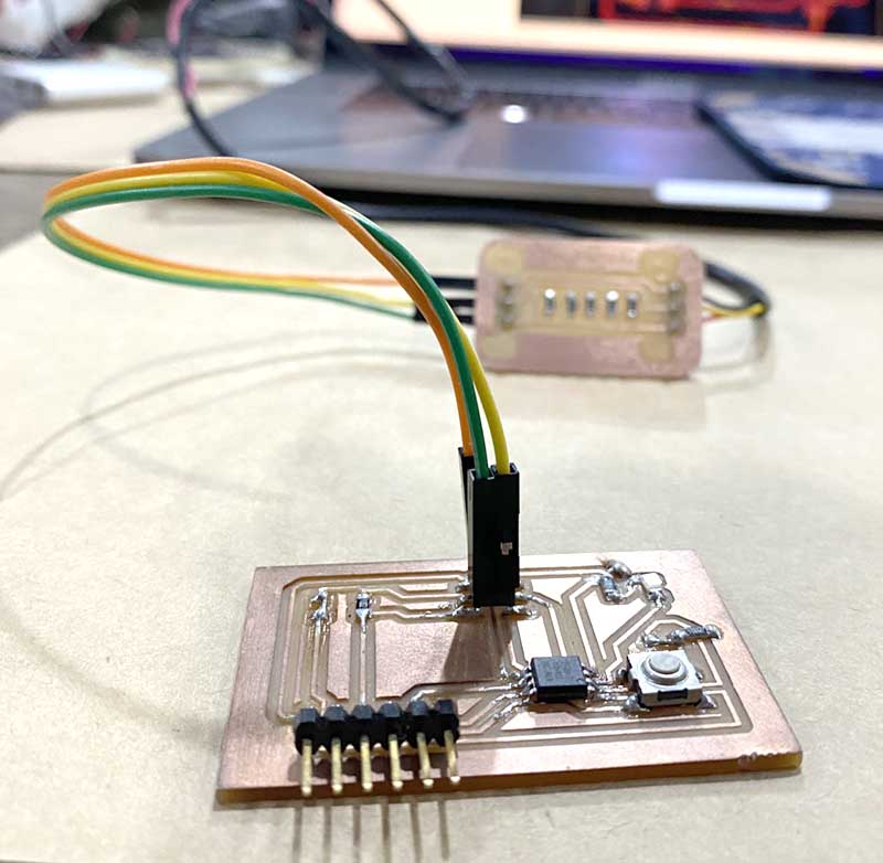
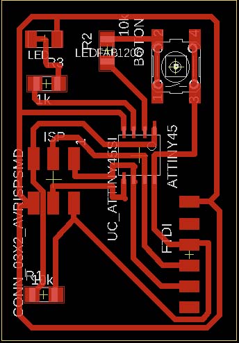
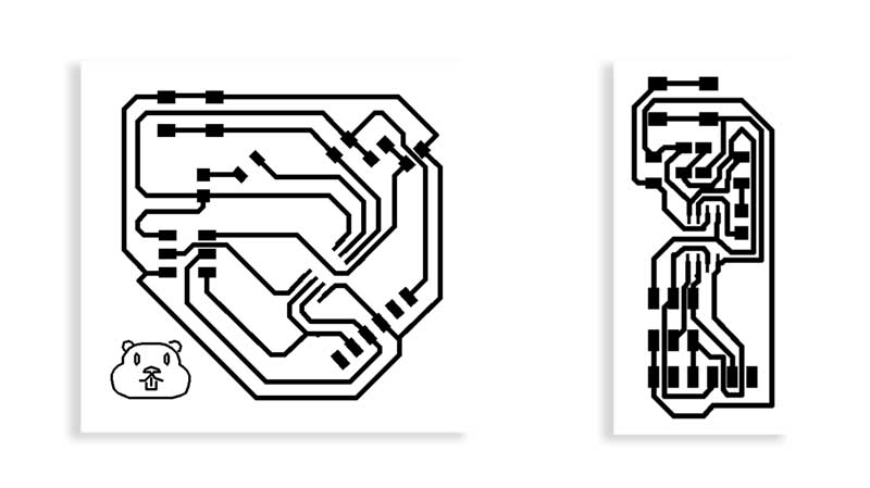
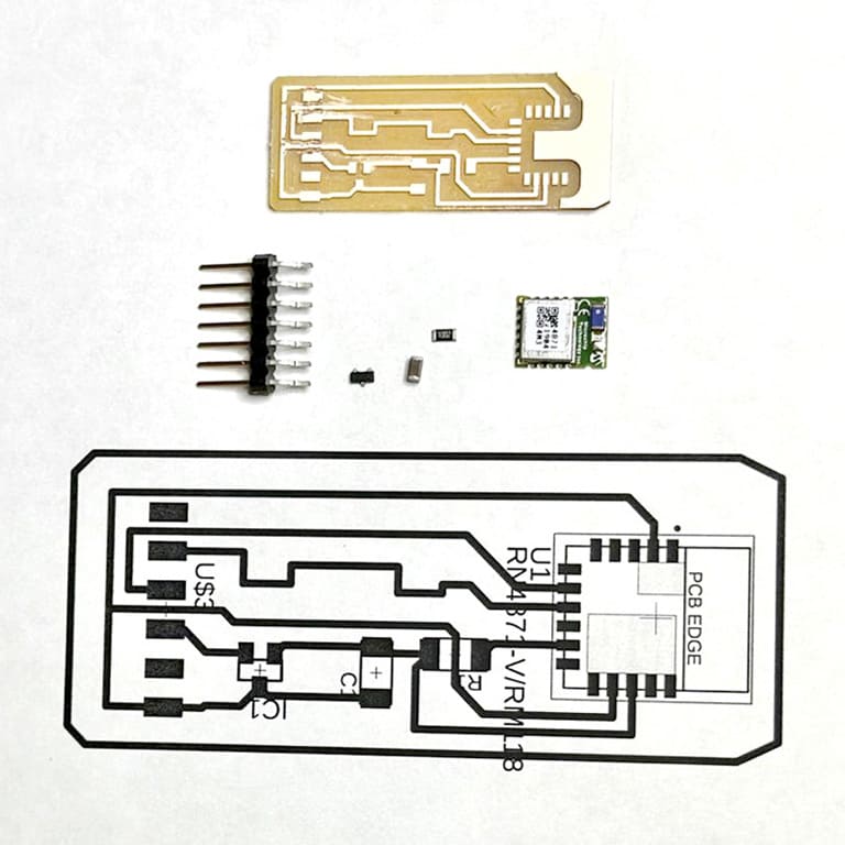
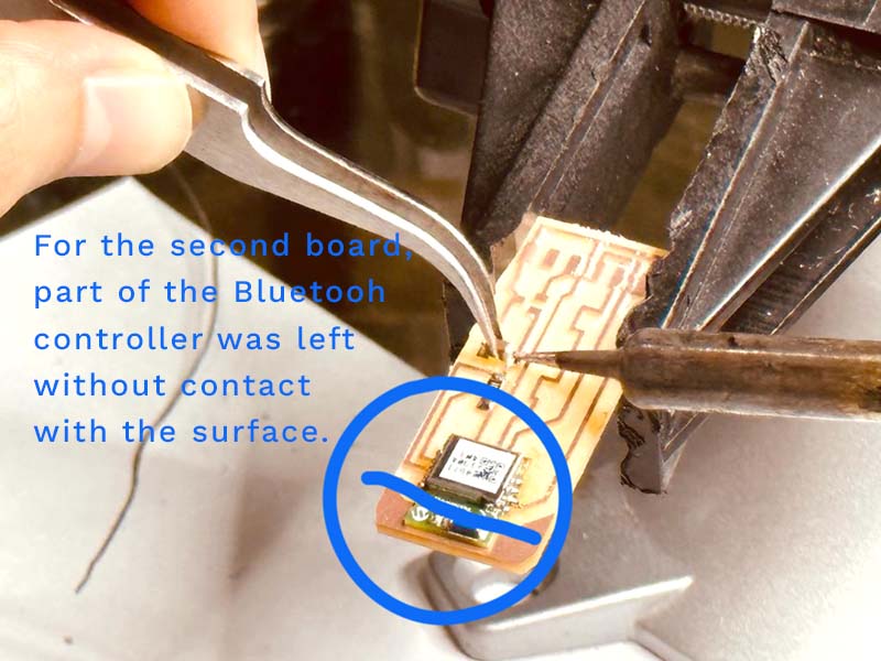
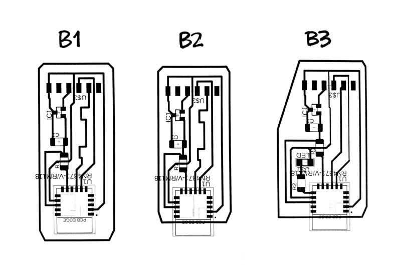
Alejandro had the task of making the schematic designed a board following the FabAcademy example, and machining it. I was in charge of soldering the components.


Bluetooth v2, v3...

The design, machining and soldering of the components went smoothly... however, when it came time for programming and verification of operation, no ☹️. Communication simply did not take place.

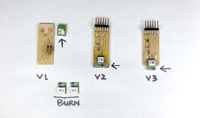
Other documentation was reviewed, the design of the first version was adjusted... and still no communication. After several adjustments, we finally performed a test with a Bluetooh HC01 module, with which we were able to establish serial communication.


Final attempt

In previous tasks related to electronics, we have already explored physical or parallel communication. In Week #4, I already performed a communication with a RaspberryPi board, using a physical Micro-USB connection.

In Week #8, I performed a parallel communication with the SIP protocol, to program the machined and soldered board through the programmer board available in the FabLab.

In Week #9, in the Output Devices, a physical connection was also made between the board and an LCD Display. In turn, in Week #10, the serial communication to transmit data to the Huevarlo controller board, and again, a Serial communication in Week #11 (Input Devices) to communicate data between the board and a capacitive sensor.


Test network and communication

For the test, we connected the t45.echo boards developed in week 8, which includes a button and an LED; and on the other hand, the sensor board developed by Alejandro in the Week #9. As for the connection, we mention that it is a physical one; for the programming of the t45.echo board we used the 1-Wire protocol that controls the temperature sensor.


1-Wire was used as the communication protocol. Is a protocol operating through one wire between the controller device and the peripheral device.


Both boards were connected by means of 3 male-male cables: one connected to VCC, one to GND and the third to the SCK of the ISP, connected to pin 13 of the microcontroller.

Code

                                    
                                            #include 
                                            #include                 
                                            #include 
                                            
                                             
                                            OneWire ourWire(2);                //Se establece el pin 2  como bus OneWire
                                            SoftwareSerial mySerial
                                            DallasTemperature sensors(&ourWire); //Se declara una variable u objeto para nuestro sensor
                                            char buttonState = '1';
                                            char lastButtonState = '0'; 
                                            int heaterPin = 13; 
                                            
                                            void setup() {
                                              delay(1000);
                                              Serial.begin(9600);
                                              sensors.begin();   //Se inicia el sensor
                                              pinMode(heaterPin, OUTPUT);    
                                            
                                            }
                                             
                                            void loop() {
                                              sensors.requestTemperatures();   //Se envía el comando para leer la temperatura
                                              float temp= sensors.getTempCByIndex(0); //Se obtiene la temperatura en ºC
                                            
                                              //Serial.print("Temperatura= ");
                                              Serial.print(temp);
                                              Serial.println(" C");
                                              //On  off heater
                                              buttonState = Serial.read();   
                                            
                                                if (buttonState != lastButtonState) {  
                                            
                                                  if (buttonState == '1') {        
                                                          
                                                    digitalWrite(heaterPin, HIGH);    
                                            
                                                  }
                                                  else if (buttonState == '0'){     
                                            
                                                    digitalWrite(heaterPin, LOW);     
                                            
                                                  }
                                            
                                                  delay(50);
                                                }
                                            
                                                lastButtonState = buttonState;                             
                                            }


In the code, the board button t45.echo is used as a virtual button, and the pin (int heaterPin = 13) of the micro-countervalue that will be the input to the temperature sensor is assigned.


Result

Another attempt at network and communication

In a new experience of connection and communication between boards, again we appeal to the many boards that we have machined, soldered and programmed: we return to the t45.echo of the Electronics Production week.

The schematic and board we see to the left is mine (it's the new Marmot version 😎), and to the right Alejandro's boards. Both have the same components: ATTiny45 microprocessor, button, led, 10k and 1k resistors, 1uF capacitor, ISP and FTDI connectors.


Schema and boards of PCB t45.echo produced in week 8.

For programming, an ATMEL ICE programmer was used, and the following code was successively loaded on both boards:

                                    
                                        #include 

                                        #define rxPin 5 // declarar el pin del RX
                                        #define txPin 4 // declarar el pin del TX

                                        // Set up a new SoftwareSerial object
                                        SoftwareSerial mySerial =  SoftwareSerial(rxPin, txPin); // Config de los pines Rx y Tx como serie de software

                                        const int BUTTON_PIN = 3; // Arduino pin connected to button's pin
                                        const int LED_PIN    = 4; // Arduino pin connected to LED's pin

                                        // variables will change:
                                        int ledState = LOW;     // the current state of LED
                                        int lastButtonState;    // the previous state of button
                                        int currentButtonState; // the current state of button

                                        void setup() {
                                        pinMode(BUTTON_PIN, INPUT_PULLUP); // set arduino pin to input pull-up mode
                                        pinMode(LED_PIN, OUTPUT);          // set arduino pin to output mode

                                        currentButtonState = digitalRead(BUTTON_PIN);
                                        }

                                        void loop() {
                                        lastButtonState    = currentButtonState;      // save the last state
                                        currentButtonState = digitalRead(BUTTON_PIN); // read new state
                                        
                                        if(lastButtonState == HIGH && currentButtonState == LOW) {

                                            // toggle state of LED
                                            ledState = !ledState;

                                            // control LED arccoding to the toggled state
                                            digitalWrite(LED_PIN, ledState);
                                        } 
                                        }


To verify the communication, each of the boards was tested connected to the computer with a FTDI type cable for the power supply of one, and with the SPI protocol between them, verifying the communication between both boards by pressing the button. The result can be seen in the video:


What I learned

😎 Types of connections and communication protocols.

😯 How two or more devices can communicate.

😬 I had a better understanding of how the electronics production performed in previous weeks worked.

How I learned it

By the assistant of the local instructors. 🙌🏼

By tutorials.

Burning boards... trying, trying, trying

What I should do

Experiment with failed wireless connection.