Sketches
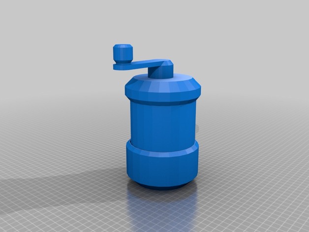
The ideation process was born from a personal need for a coffee grinder. For this, I made several sketches and also resorted to an idea generation exercise using Artificial Intelligence platforms such as Midjourney, DreamStudio and Adobe Firefly.
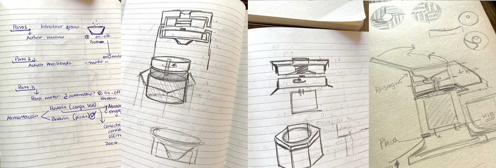
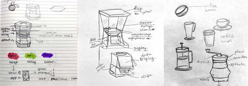 Sketch of MoliNito, with basic functions (Date: march).
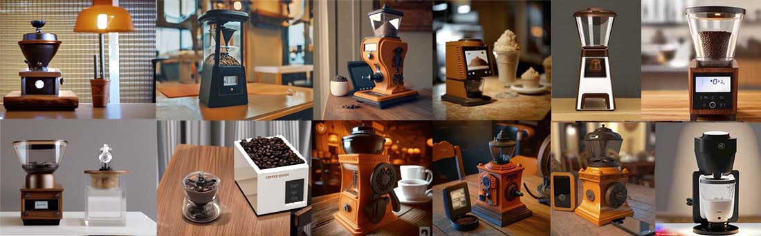 Images generated width AI platforms (Date: march).
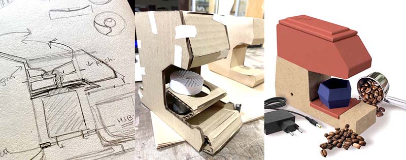
Form final finding (Date: may-june).
Functional references
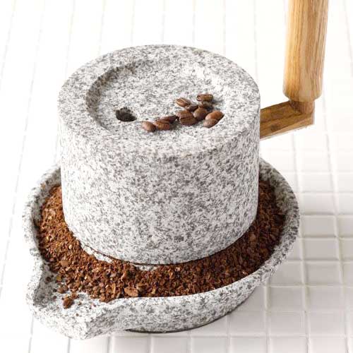
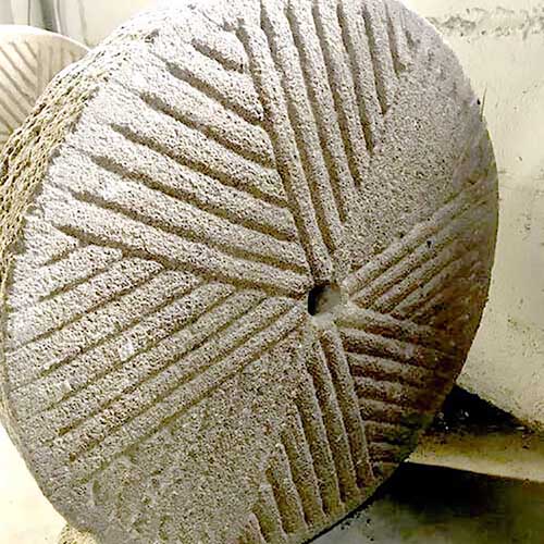
The old stone mills used to grind corn were taken as a reference for the design of the product. In addition, several projects of electric mills were compiled, which served as a basis for determining the final shape and mechanism of MoliNito.
The project is based on components, mechanisms and systems of several coffee mill projects that use additive and subtractive technologies, in addition to electronics, and that were found in several platforms. MoliNito' has as its documentary-technical basis the following:
On top: coffee grinder projects found on instructables.com and thingivese.com; and search result for stone grinder references on Pinterest (bellow).
Formal references
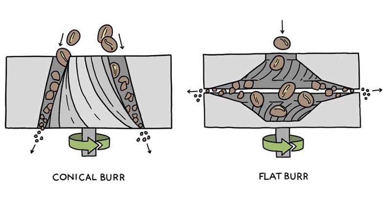
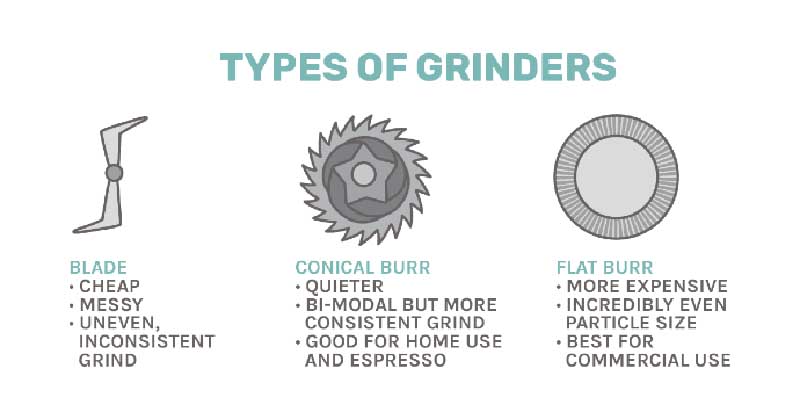
As for the formal references, I focused on the design of the grinding wheels. There are several models of coffee wheels: burr (conical or flat) and blade.
Development
2D
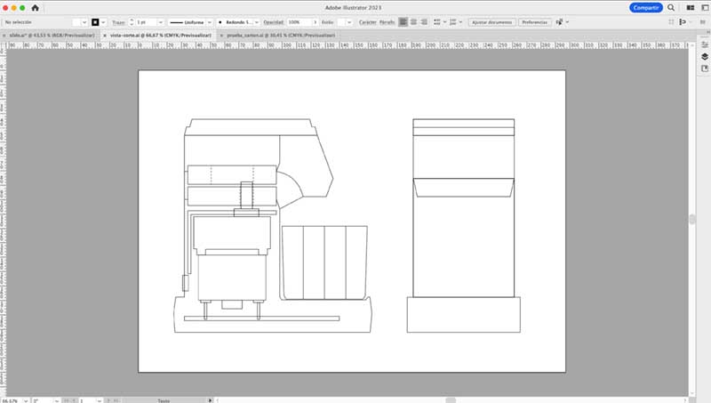
As a first approach to the CAD of the project, I first made a sketch in Adobe Illustrator of a lateral cut of the product to visualize how the space and components are organized.
I also made a drawing that serves as an ornament, based on the chemical bond of caffeine.
Also, but from the 3D drawing, I obtained the drawings that were taken to laser cutting. In this case, we are talking about the parts of the MoliNito structure that were produced with 3.7 mm thick plywood.
As for the pressfit value for the sockets, the respective test was carried out, which yielded a value of 0.37 mm.
To insert a kerfing that allows the material to be folded on one of the faces (back) of the lower structure, the formula was applied: Kerf = Thickness / 10
After finishing the drawing, the .dxf files were generated to perform the nesting (distribution of parts for cutting).
The following parameters were used for cutting:
Note: after the presentation of MoliNito, I designed a blanket using a fabric known as 'Polar', which is similar to wool, but synthetic, which has 100% polyester in its composition. A design was elaborated that does not use any other aggregate but sockets made with the same material to make the assembly. The laser cutting parameters applied were: for the cutting, power 60/speed 100 and for the engraving of the ornament, power 20/speed 100.
3D
Then, I started the 3D drawing of the components, using the Fusion 360 software, although in some moments I made some structures in Bezel.
Mills and Funnel
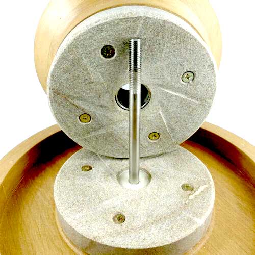
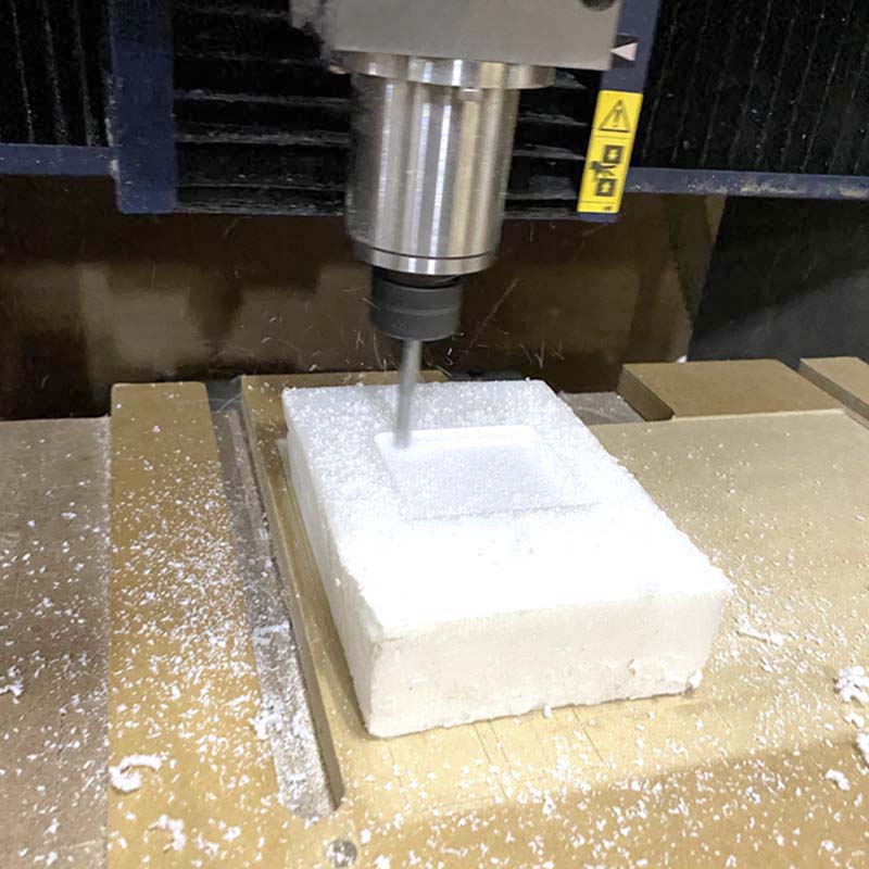
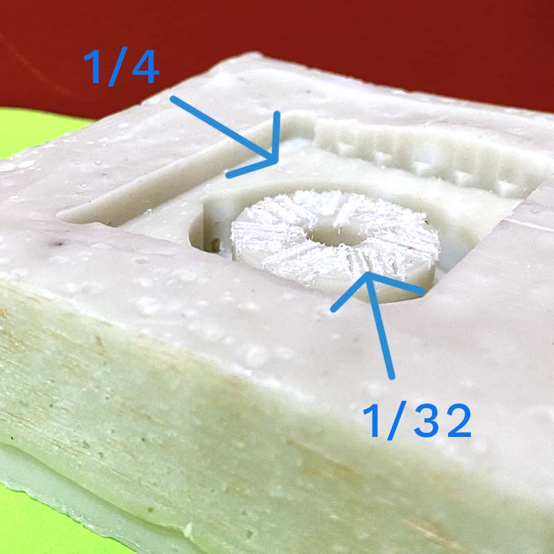
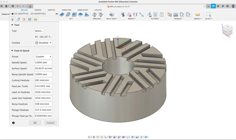
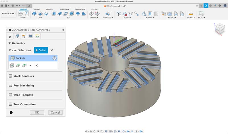
First I made the millstones of the mill, opting for the flat design. During the week of Molding and Casting, I reliced the design of one of the millstones, to analyze the shape and type of production by molds (this will be further explored, to realize the mills with ceramics).
I then began explorations and new designs, this time using 3D printing with PLA filament.
Once the lower and lower mills were made, I made an integration of the upper mill to what is the top of the mill, and print a single object. For this purpose, I also design a funnel, which is used to deposit the grains so that they fall and the grinding process begins when they are trapped between the upper and lower grinding wheel, which is attached to the motor shaft.
Left: Upper grinder. Rigth: Lower grinder.
Left: Funnel design. Rigth: Integration funnel + upper grinder.
Integration funnel + upper grinder + lib.
Other Components
Other components developed for 3D printing were: a support for the motor and a support for the electronic board. The support and the knob for the potentiometer were models already made and used in other projects. A central bed, on which the milled grain collector cup is placed; and a sliding structure through which the milling slides to the outside and which protects the motor and the electronics.
With the exception of the potentiometer knob, PLA filament was used for all 3D printed components. TPU was used for the knob to obtain a component with flexibility, which allows inserting the knob to the shaft of the potentiometer without much resistance.
Left: the PCB mount consists of two parts: the lower part, where the board is mounted, and the upper part, which covers it, and on which the motor mount is placed. Right: Sliding structure.
Left: Motor mount. Right:Potentiometer knob in Thingiverse
Left: Potentiometer mount. Right: Collector vessel.
Support base.
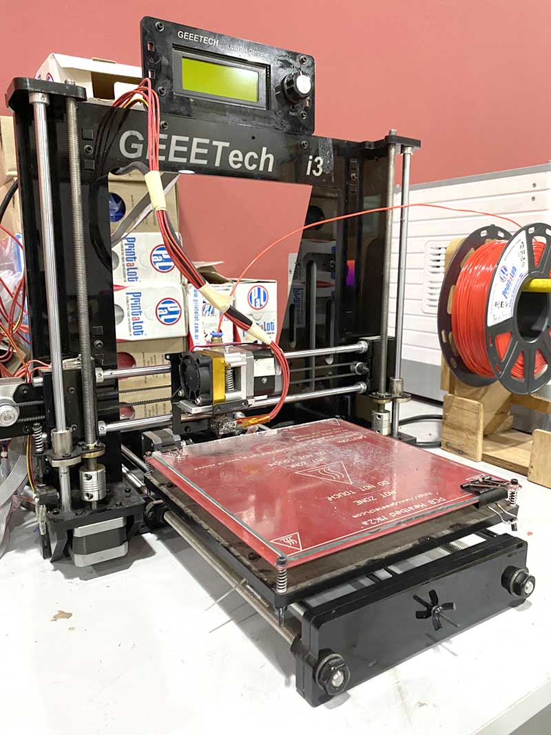
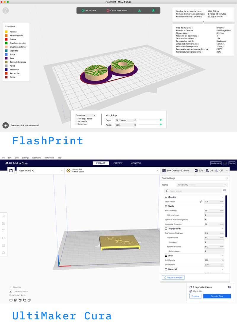
For production, two printers available in the FabLab were used: a Flashforge (week 5) and a GEEETech i3. FlashPrint5 and UltiMaker Cura software were used to prepare the files.
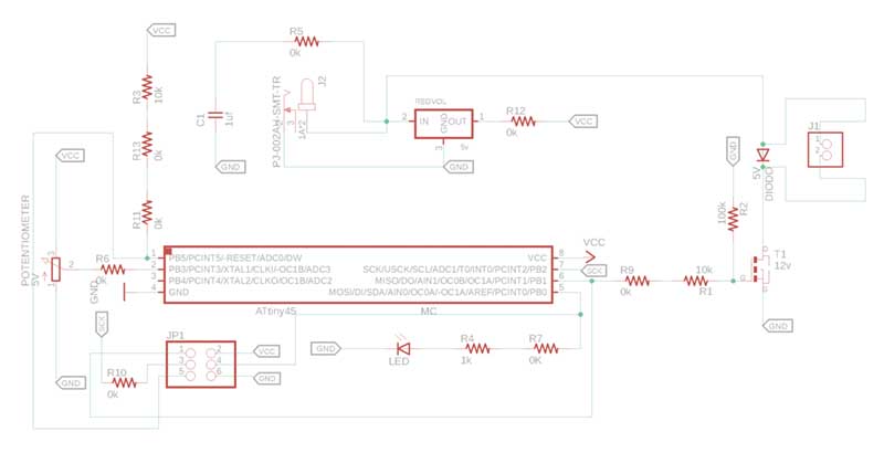
Electronics
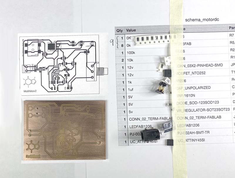
As for the electronics, MoliNito PCB is a controller comprising the following components:
| Quantity |
Description |
Value |
| 9 |
Resistor |
0 Ω - Jumper |
| 1 |
Resistor |
1 Ω |
| 2 |
Resistor |
10 Ω |
| 1 |
Resistor |
100 Ω |
| 1 |
Mosfet N-CH |
50V |
| 1 |
Capacitor |
1uf |
| 1 |
Voltage regulador |
5V |
| 1 |
Potentiometer |
1k |
| 1 |
LED green |
|
| 1 |
Pin header male |
2x3 |
| 1 |
Power Jack |
2.5x5.5 mm Solder |
| 1 |
ATTiny |
45 |
| 1 |
Copper board |
150x150 mm |
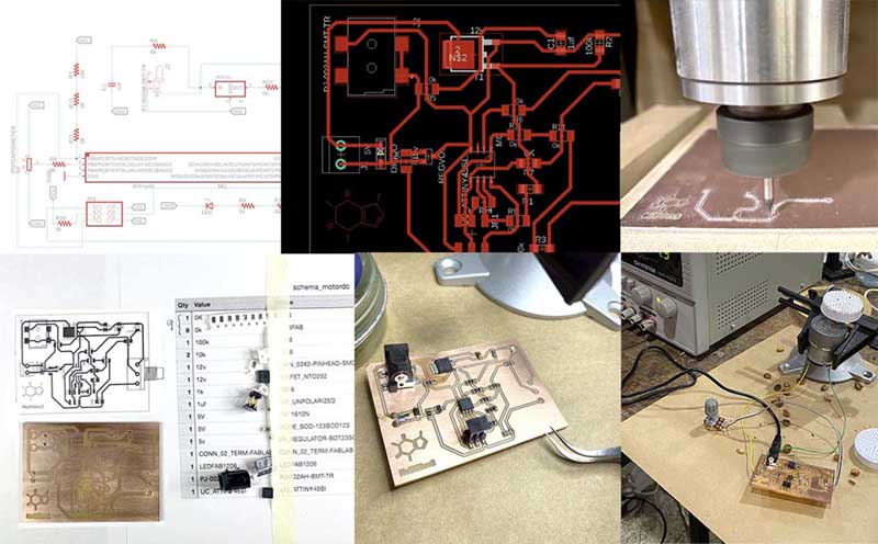
The microcontroller used is an ATTiny45, as a power source a Power Jack connector, a potentiometer to enable/disable the 12V DC motor and the connection components to the motor and another to establish SPI communication for programming.
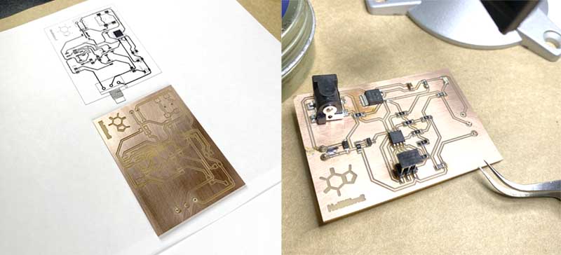
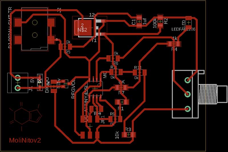
First I traced the circuit on paper, then started to design the schematic in Eagle to then obtain the board and proceed to the machining: generating the CAM files from Eagle and then generating the g-code in FlatCam. A 1/64 milling cutter was used for milling and drilling the circuit, and a 1/34 milling cutter for cutting. Then the soldering of the components to move on to programming.
Programming
The code for programming the motor is quite simple, since only one motor has to be activated with the potentiometer.
                                            const
                                            int pinPot = 3;//the analog input pin attach to
                                            const
                                            int pinMotor = 1;//the led attach to
                                            int
                                            inputValue = 0;//variable to store the value coming from sensor
                                            int
                                            outputValue = 0;//variable to store the output value

                                            void setup() {
                                                pinMode(pinPot, INPUT);
                                                pinMode(pinMotor, OUTPUT);
                                            }
                                            void loop() {
                                                inputValue = analogRead(pinPot);
                                                outputValue = map(inputValue, 0, 1023, 0, 255);
                                                analogWrite(pinMotor, outputValue);
                                                delay(1000);
                                            }
BOM (Bill of materials)
Electronics
| Quantity |
Description |
Value |
Unit Price |
Total |
| 9 |
Resistor |
0 Ω - Jumper |
$ 0.10 |
$ 0.90 |
| 1 |
Resistor |
1 Ω |
$ 0.10 |
$ 0.10 |
| 2 |
Resistor |
10 Ω |
$ 0.10 |
$ 0.20 |
| 1 |
Resistor |
100 Ω |
$ 0.10 |
$ 0.10 |
| 1 |
Mosfet N-CH |
50V |
$ 1.11 |
$ 1.11 |
| 1 |
Capacitor |
1uf |
$ 0.10 |
$ 0.10 |
| 1 |
Voltage regulador |
5V |
$ 0.36 |
$ 0.36 |
| 1 |
Potentiometer |
1k |
$ 5.98 |
$ 5.98 |
| 1 |
LED green |
|
$ 0.26 |
$ 0.26 |
| 1 |
Pin header male |
2x3 |
$ 0.55 |
$ 0.55 |
| 1 |
Power Jack |
2.5x5.5 mm Solder |
$ 0.71 |
$ 0.71 |
| 1 |
ATTiny |
45 |
$ 2.23 |
$ 2.23 |
| 1 |
Copper board |
150x150 mm |
$ 2.00 |
$ 2.00 |
|
|
|
TOTAL |
$ 15.67 |
Cost
The cost of the MoliNito prototype would be
| Description |
Cost |
| Electronics |
$ 62.9 |
| DC Motor Pololu |
$ 33.95 |
| 3D printing |
$ 178.8 |
| Laser cutting |
$ 7.8 |
| Total |
$ 283.4 |
Project development
To organize product development ideas, I use the Notion application to jot down ideas and data to move production forward.
License

Esta obra está bajo una
Licencia Creative Commons Atribución-NoComercial-CompartirIgual 4.0 Internacional.