Week 3

Computer-Controlled Cutting

By Patricia Samudio Salinas β€” on

Computer-Controlled Cutting

Hey there! Can you believe we're already in the third week? We've had the chance to interact with some of the machines in the fab lab, which is pretty exciting! πŸ˜… Now, it's time to get down to business and start making some cuts with the cutting plotter and laser. Let's get to it! βœ‚οΈ

So, this week we started working as a team and one of the tasks was to check out the tech available at the Fab Lab CIDI Universitario in San Lorenzo, Paraguay.

For this that task, we’ve been hitting up the instructors and checking πŸ‘€Β out the fabers 2022 documentation, since there were no changes or new additions made. The equipment remains the same 😎.

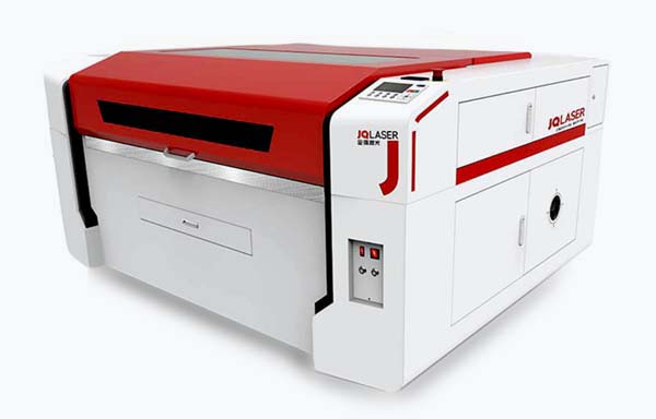
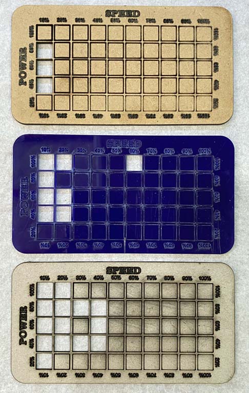
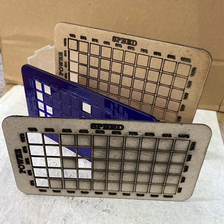
We tested the laser cutter and cutting plotter with different materials, and also learned about their models and features.

Vinyl cutting

In our lab, the vinyl Cutter machine that we have is a GCC Puma IV 60 LX. Some this features are:

  • Max width: 600 mm
  • Max length: 500 mm (roll type)
  • Max thickness: 0.8 mm
  • Max cutting force: 500 g
  • Max cutting speed: 1020 mm/s

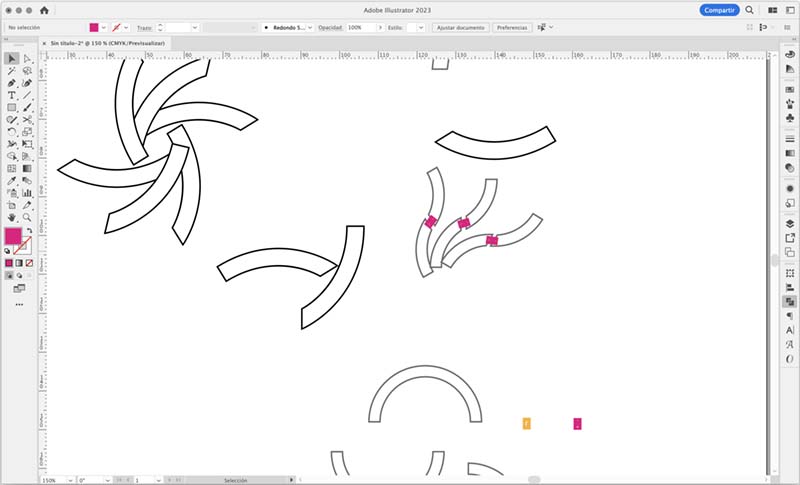
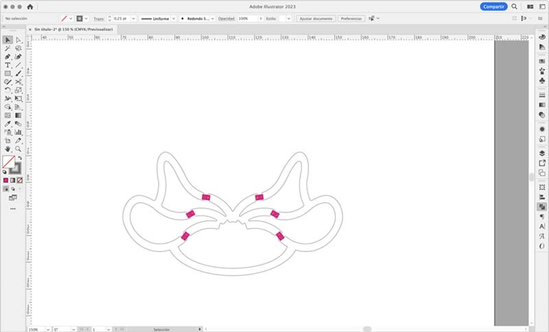
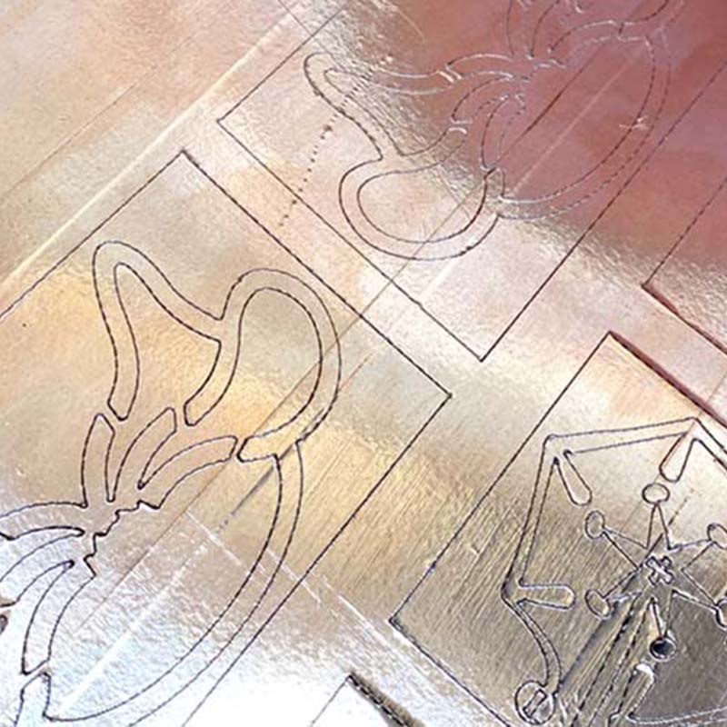
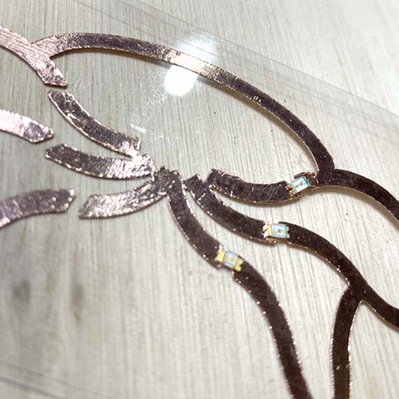
For preprocessing the images that I wanted to cut, I used Adobe Illustrator. I drew a circuit using a rectangular shape, smoothing out the lines and then applying a reflection to the shape to obtain the final design. The document was prepared with the .dxf extension 😎.

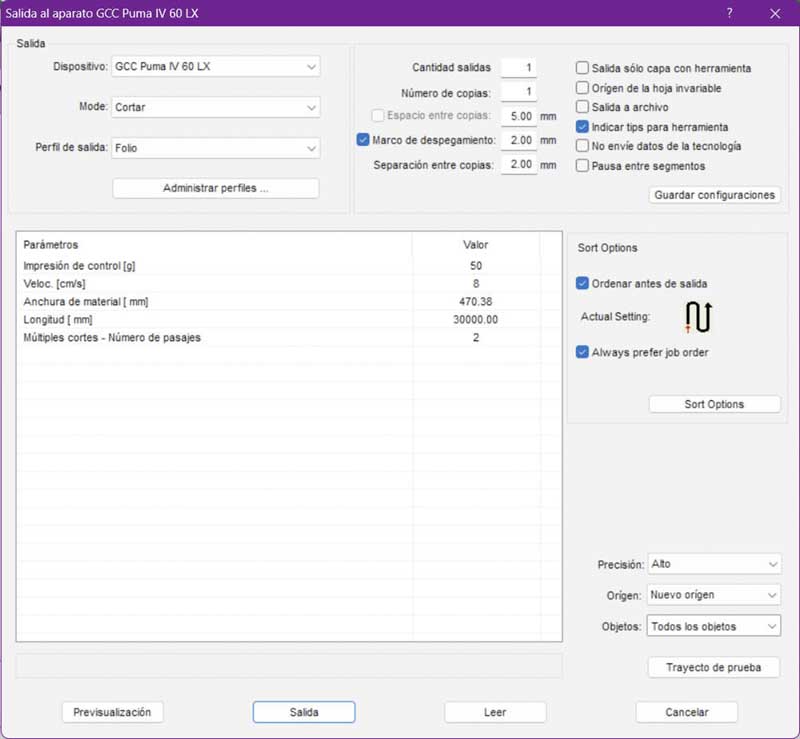
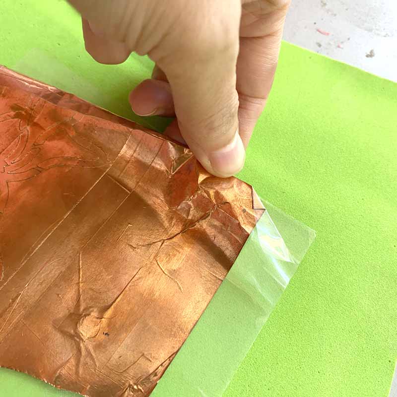
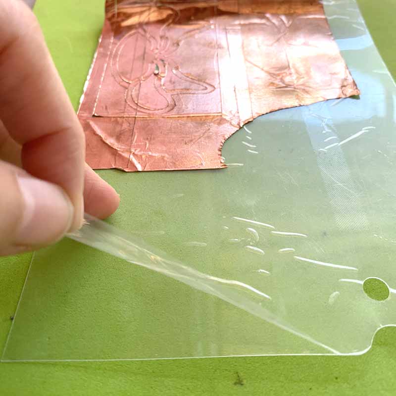
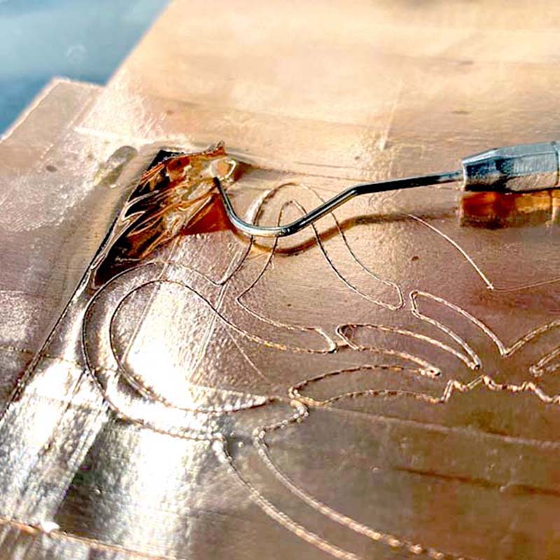
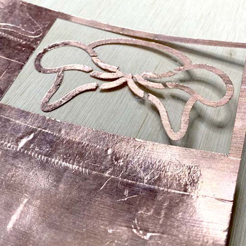
In the Vinyl Cutting Software (GreatCut 4), I imported the .dxf file; we used adhesive copper tape, attached to an acetate board to take it to cut.


Setting for the cutting
  • Speed: 12 cm/s
  • Pressure cutting: 50

Screenshot of GreatCut software parameters window.

Here is the result ✌🏽:


NOTE: In the first cut, I had not removed the foil covering the acetate base plate to which the copper foil was adhered for the cut πŸ˜…, which made it difficult to remove the negative parts. On the second attempt, success led to the completion of the task 😎.

Laser cutting

The FabLab CIDI Universitario is equipped with a JQ Laser JQ-1390 Laser Cutting Machine, installed in an isolated room with ventilation and refrigeration systems.

  • Laser type: Sealed CO2 laser tube
  • Laser power: 80W Beijing Reci brand
  • Maximum cutting area: 1300 x 900mm

So, in the lab, we have a whole bunch of materials like acrylic, gray cardboard, corrugated cardboard, MDF, and plywood. When we're testing power and speed, we usually mess around with three of them that are between 1.45 and 4 mm thick.

In order to cleanly cut that material, there are some parameters and values that we had to set.

  • The laser power is measured in a percentage from 0% to 100%. When you're working with delicate materials like paper o textiles, you'll want to use low values. But for resistant materials, you'll need to use higher values.
  • Cutting speed is measured in mm/s. If it goes fast, the laser does not spend much time on the material, but if it goes slow, the cutting time takes longer.

For the speed-power test, we used three materials: acrylic (2.3 mm), MDF (3 mm) and gray cardboard (1.4 mm).


So, on Monday the 10th, we had this really scary moment with the machine 😱 πŸ”₯. We were testing a cardboard cut and suddenly it caught fire, which caused the air hose connected to the laser support 😢 to burn in a pretty big way πŸ™ˆ. But thanks to the instructor's cleverness πŸ₯·πŸ», we figured out how to fix the component by using a spare hose and insulation tape as a sort of temporary fix until the technicians can take a look at it and replace it. Mind blown! 🀯 We must also say that, in our opinion, this 'homemade' repair improves the performance of the air output πŸ’¨πŸ’ͺ🏽.

Parametric kit

As an individual task, the challenge consist in designing a parametric system of pieces with joints was requested, for which the results of the tests carried out on the laser cutting machine were used.

3,5,6 press fit kit

  1. Once the forms were determined, the Fusion 360 application was used to rasterize and parameterize them.
  2. I used the Fusion 360 application to make the component shapes of the kit.
  3. In the same application, the forms were parameterized according to the chart.
  4. To assemble the pieces so that they can be cut, I used the application DeepNest.
  5. The .dxf file was generated and then the acrylic was cut at 2.5 mm.


What I learned

🀯 The process of parameterization of 3D drawings or schemes (the concept itself is already known to me, since in Editorial Design the same concept is used for the visual elements of a publication).

πŸ˜… Never, ever lose sight of the cutting process, especially if it involves easily combustible materials.

😳 Never trust the thickness of materials. There are conditions that make them variable. Measure every time a project needs to be processed.

How I learned it

By the guidance of the local instructors and colleagues πŸ™ŒπŸΌ

Through the observation of known tools πŸ‘€

Through essay and error

What I should avoid

Wanting to experiment (for now) with too many options 😰. It will be difficult, but I will try.

What I should do

Continue practicing/exploring the functionalities of Fusion.

Perform kerf, power and speed tests with other materials.