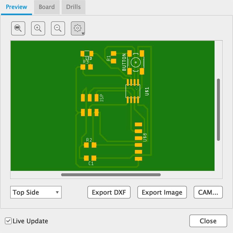
Electronics Design
Well, here I am... six weeks after starting that thing that is the Fab Academy (who would have guessed 😅). In this week we have been select and use software for circuit board design 🤯 and demonstrate workflows used in circuit board design. For me this world is a strange universe to explore and learn 🤔.
In the class on Wednesday, March 1, a series of information and resources were shared to guide the work, and on how to meet the proposed goals: design a development board to interact and communicate with an embedded microcontroller 🫣.
To this end, my first personal task was to "review and expand, if necessary, the information" on electronic design. While in the subtractive systems week we had a first experience with 'circuits', it now became a bit more complex. Having to rediscover laws associated with physics and solve computational problems is quite a challenge 😅.
I drew on the information distributed on the homework page for the week, as well as reinforcing some of the information through other resources such as Khan Academy and Wikipedia articles (in my native languaje 🇪🇸).
Eagle
As software for the board design, I chose Eagle first because of its ease of interoperability with Fusion, and then because the other one suggested requires quite considerable memory.
EAGLE is electronic design automation (EDA) software that lets printed circuit board (PCB) designers seamlessly connect schematic diagrams, component placement, PCB routing, and comprehensive library content.
And since I already have some knowledge of the Fusion framework, it seemed more appropriate to start with this application (I also reviewed the Flux platform, and found it quite easy to learn, and that will be a platform I will be reviewing another time).
Schematic design
During the weekend meetings with the instructors, we started the schematic design of the circuit (I must point out again, a whole new world for me 😅). As first important information to note is the symbology of the components of an electronic circuit.
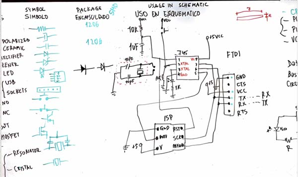
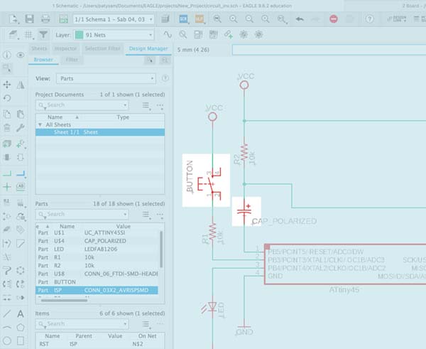
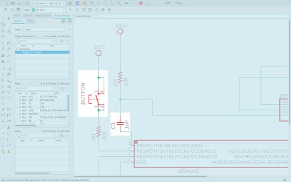
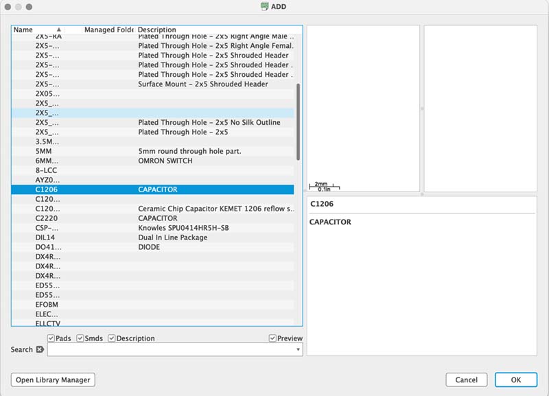
And then, start the schematic design in Eagle. I selected the components, from the integrated library or we can also include a particular library. In this case, we include the library provided by the Fab Academy.
I placed the components to form the circuit: a microcontroller (ATTiny 45), three resistors, a button, a LED, an ISP and an FTDI. Besides including other elements such as GND and VCC terminals. Cool! 😎.
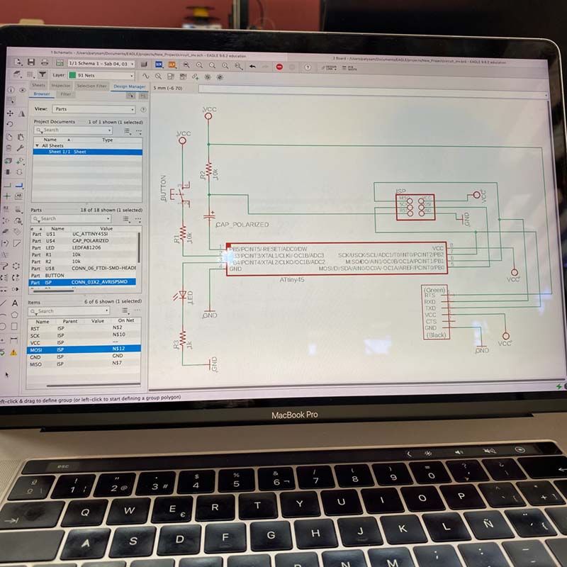
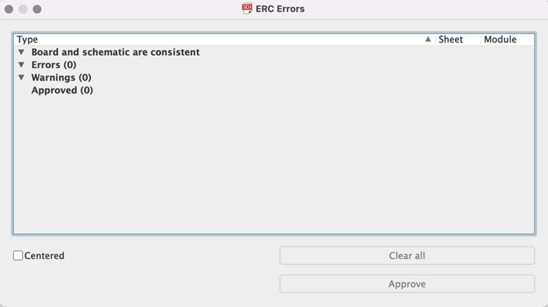
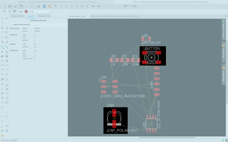
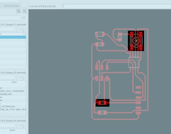
Once the schematic is finished, I print it to check that each element is correctly connected. And then I use the Consistency Check -ERC- function, then switch to Board mode and start the routing mode.
